Electron Microscope Analysis of Low Temperature Damage
in PEM Fuel Cells
By Eric L. Thompson
Department of Chemical Engineering,
Abstract
PEM fuel cells
electrochemically combine hydrogen and oxygen to produce electricity and
water. Because of their environmental
friendliness and use of alternative fuel, they are being investigated by the
automotive industry as a replacement for the gasoline engine. In order to meet automotive targets, PEM fuel
cells must be able to start, operate, and survive reliably from sub-freezing
temperatures. Considering the facts that
water is generated within the fuel cell, and is often provided as external
humidification, these pose a significant concern for low temperature
operation. In this study, several low
temperature failure modes are investigated in PEM fuel cells that underwent
multiple freeze start and operation events from -20 C. Samples were removed from the fuel cells and
analyzed with electron microscopy techniques.
Introduction
PEM (polymer
exchange membrane) fuel cells are electrochemical devices in which hydrogen and
oxygen (from air) are combined to produce water. Reactant gases enter the fuel cell through a
set of flow fields. Often, the gases are
humidified before delivery to the fuel cell.
The purpose of the flow field is to evenly distribute the reactant gases
as well as carry away the unused gases and product water. Once gases enter the fuel cell, they diffuse through a porous “backing
layer”, commonly known as diffusion media.
Gas can freely diffuse through this backing layer toward the electrode,
where reaction occurs. Product water can also diffuse or flow away from the
electrode, particularly on the cathode side.
Often a micro-porous layer (known as an MPL) is included in the fuel
cell structure, between each backing layer and electrode. The purpose of the MPL is to provide a
transition between the backing layer and electrode and assist in product water
transport. The electrodes are also a
micro-porous structure of carbon spheres coated with a finely dispersed
catalyst, which speeds the kinetics of the electrochemical reactions. At the anode, hydrogen is oxidized:
2H2 ↔ 4H+ + 4e-
While at the cathode oxygen is
reduced to water according to the reaction:
O2 +
4H+ + 4e- ↔ 2H20
The hydrogen (anode) and
oxygen (cathode) remain separated by a thin membrane made of a unique polymer
material. This polymer (known as an
ionomer) has the ability to conduct protons but insulates electrons, and gives
the fuel cell the ability to function.
On the anode side, hydrogen dissociates into protons (H+) and electrons (e-). The protons
travel through the membrane to the cathode, but the electrons cannot. They are forced through an external circuit,
where they can do useful work, such as powering an electric drive motor. The humidification of the membrane helps
determine its ability to conduct protons, and is a primary reason for pre-humidification
of the reactants. Often, the electrodes
are permanently applied or hot-pressed to the membrane to form what is known as
a membrane electrode assembly (MEA). The
following sketch was taken from Fuel Cells-Green Power; an informational
booklet provided by Los Alamos National Labs which is available online at www.education.lanl.gov/resources/fuelcells. This sketch nicely illustrates the structures
and process occurring within the fuel cell.
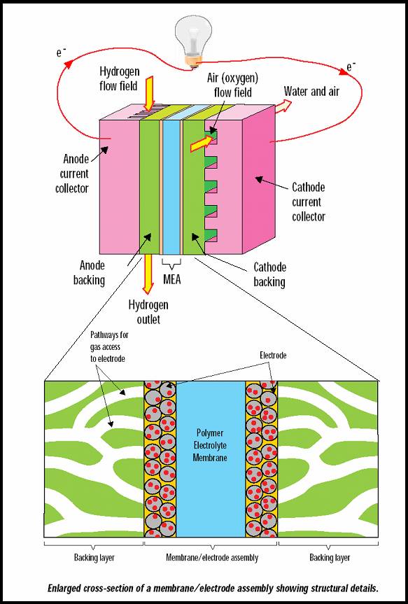
Figure 1. Sketch of PEM fuel cell showing internal
components
One can imagine that due to the formation of product water
within the fuel cell, the presence of water-filled pores or flow field channels
could lead to problems when retained water is allowed to freeze and undergo 10%
volume expansion. Often a purge is
performed at shutdown, prior to freezing, to remove liquid water (U.S Patents
#6,479,177 B1, #5,798,186). This purge
is ineffective at removing all water from within the cell, so some ice
formation is inevitable. One aspect of
this study is to determine the effect that freezing of residual water has on
the structures within the fuel cell. The
examined mechanisms of hypothesized damage are as follows:
· Water is present, in either liquid or vapor phase, in
all operating PEM fuel cells. Following
operation, if the fuel cell is exposed to sub-freezing temperatures, this water
may freeze and damage the internal structures.
One way to distinguish between different flow field designs is their
ability to remove and minimize the retention of bulk water and large droplets
in flow field channels during operation.
For the purpose of this study, a flow field design that is effective at
removing bulk water and droplets is referred to as a water-clearing fuel
cell. On the other hand, some flow field
designs have been shown to trap or hold bulk liquid water and droplets in
specific locations of the flow field.
This type of flow field design is referred to as a water-trapping fuel
cell. In the first part of this study, a
comparison of damage to the backing layer and electrode structures from two
different fuel cells; one with a water-trapping flow field, the other with
water-clearing flow field is made. Ice damage to the backing layer and
electrode is expected in the water-trapping fuel cell. Each fuel cell underwent
multiple freeze start and sub-freezing operation events, in which product water
could freeze and cause damage to the internal components. Microscope analysis includes low magnification
images to illustrate large scale damage as well as high magnification images to
determine if damage is occurring to fine structures that would inhibit the
electrochemical process or diffusion of reactants.
· Since the outlet of the cathode side is the exit for
all product water generated over the entire electrode, it is presumably the
wettest region within the fuel cell, and potentially is the most probable
location for ice damage to occur. This
is true regardless of whether the flow field design is water-trapping or
water-clearing. Based on the knowledge
that a water-clearing fuel cell does not retain much bulk water in the flow
field, a question still remains whether the outlet region would undergo any
damage after freezing, especially to the fine pore structures of the electrodes
and MPL. Presumably these fine pore
structures could contain significant water near the cathode out, even if the
adjacent flow field does not have bulk water present. Samples of the backing layer, MPL and
electrode structures were collected from the inlet and outlet regions of a
water-clearing PEM fuel cell and compared to new samples of each material. Both high and low magnification SEM images
are collected. Since less large-scale
damage to backing layers is expected in water-clearing fuel cells, the main
goal is to determine if any small-scale structural damage in the electrode and
MPL is present.
· Finally, a common technique for assisting cold starting
of PEM fuel cells is to provide a mixture of reactant gases to a single
electrode (International Patent WO 00/54356).
The gas mixture should be below the lower explosion limit of 4% hydrogen
in air. For example, 2.5% hydrogen is
mixed with the air and delivered to the cathode electrode. This mixture reacts exothermically on the
electrode catalyst, and provides additional heat to warm the cell up. Catalyst sintering (Oswalt ripening) is known
to occur in dispersed catalysts at elevated temperatures. Since not much is known about the local
electrode temperatures during this process, an investigation of the catalyst
particle sizes was conducted with a TEM.
Electrode sections were taken from the leading edge of a fuel cell
electrode and compared to a new sample to investigate changes in particle size.
Results
Observed Damage to Backing Layer and Membrane Electrode
Assembly (MEA) in Water-Trapping Fuel Cell Compared to Water-Clearing Fuel Cell
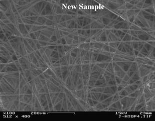
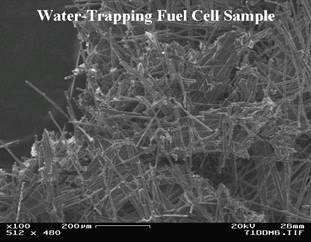
Figure 2. New
backing layer sample compared to damaged sample from bulk water location of a
water-trapping fuel cell.

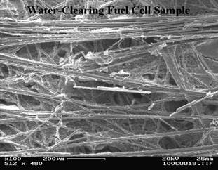
Figure 3. New
backing layer sample compared to sample taken near cathode outlet region of
water-clearing fuel cell.
Figures 2 and 3 illustrate
the difference in backing-layer damage observed in two fuel cell types. Images of new samples are provided for
reference and to illustrate the overall magnitude of the damage. It is apparent from Figure 2 that locations
which trap or hold bulk water during operation undergo massive damage when
exposed to freezing temperatures. The
water-clearing design does not appear to suffer from this problem, as only
minor damage was found near the cathode outlet.
This was the worst example of backing-layer damage found in the
water-clearing design, which otherwise appeared undamaged.
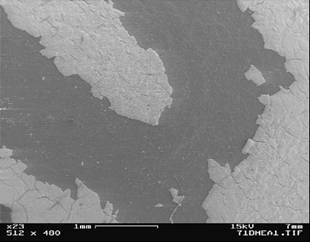
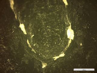
Figure 4. SEM
(left) and Light Micrographs (right) showing damaged MEA samples having loss of
electrode from freezing of water-filled channel of water-trapping fuel cell.
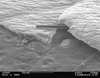
Figure 5. Damaged
MEA sample showing broken backing-layer fiber lifting a section of electrode
from membrane near water-filled channel of water-trapping fuel cell.
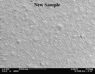
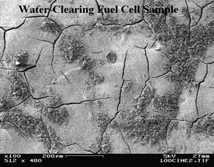
Figure 6. New
MEA (electrode) sample compared to a sample taken from electrode near cathode inlet
of water-clearing fuel cell at low magnification. Note that some of micro-porous layer remains
adhered to electrode in post frozen sample.
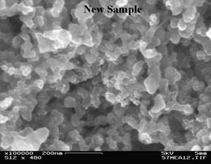
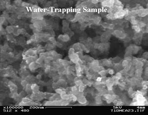

Figure 7. High
magnification images of new MEA (electrode) sample compared to a samples taken
from damaged electrode of the water-trapping fuel cell and cathode inlet of a
water-clearing fuel cell.
Figures 4 and 5 illustrate
the massive damage observed at an MEA taken from a location of bulk
water-filled channel in a water-trapping fuel cell design. Freezing of water has de-laminated the
electrode off the membrane over the entire channel region. Also, evidence of the mechanism of how this
occurs is given by the broken backing-layer fiber lifting the electrode structure
away from the membrane. Figure 6
compares a new electrode to one removed from a water-clearing fuel cell. Note that although there appears to be more
electrode cracking in the used sample, none of the electrode de-lamination has
occurred as observed in the water-trapping design. Finally, Figure 7 examines damage at a
smaller scale. This figure compares a
new sample to those obtained from the post frozen fuel cells at high
magnification. From this figure, it does
not appear that any damage is occurring to the electrode structures on a very
small scale.
New Backing-Layer, Micro-porous Layer (MPL), and MEA
Electrodes Compared to Samples Obtained From Inlet and Outlet Regions of a
Water-Clearing Fuel Cell
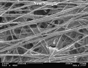
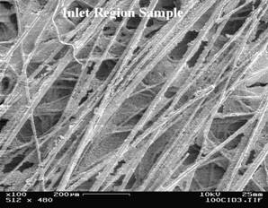
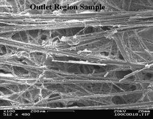
Figure 8. New
backing-layer sample compared to samples taken from the cathode inlet and
cathode outlet regions of a water-clearing fuel cell.
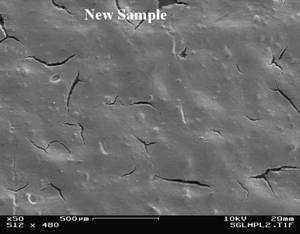
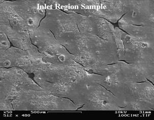
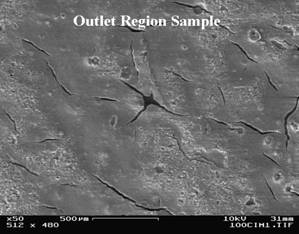
Figure 9. New
micro-porous layer (MPL) sample compared to samples taken from the cathode
inlet and cathode outlet regions of a water-clearing fuel cell at low magnification.
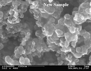
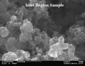
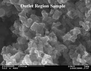
Figure 10. New
micro-porous layer (MPL) sample compared to samples taken from the cathode
inlet and cathode outlet regions of a water-clearing fuel cell at high
magnification.

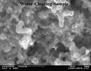
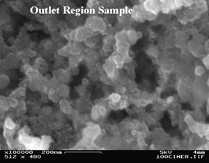
Figure 11. New
MEA electrode sample compared to samples taken from the cathode inlet and
cathode outlet regions of a water-clearing fuel cell at high magnification.
Figure 8 shows that some minor
damage to the backing layer fibers and binder is occurring near the wet,
cathode out region of a water-clearing fuel cell. The inlet region appears to look undamaged,
as compared to the new sample. Figures 9
and 10 show the micro-porous layer. In
the low magnification image, cracking is present in the new sample, as well as
those obtained from the inlet and outlet regions of a water-clearing fuel
cell. In the high magnification image,
Figure 10, no major damage is observed in the micro structure of the MPL, even
in the wet outlet region. Similarly, at
high magnification, the electrode does not appear to show signs of damage
following the freeze events, as shown in Figure 11.
New Electrode Catalyst Compared to Samples Obtained
From Inlet and Outlet Regions of a Water-Clearing Fuel Cell
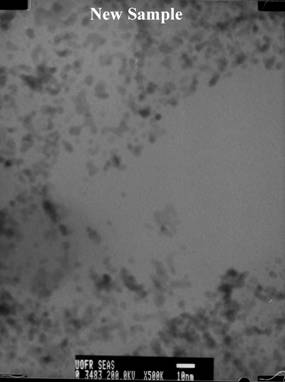
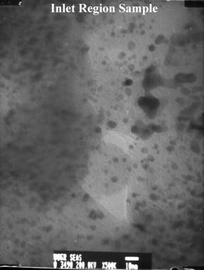
Figure 12. New electrode microtome section compared to sample taken from the cathode inlet region of a water-clearing fuel cell that underwent catalytic heating. (500,000x)
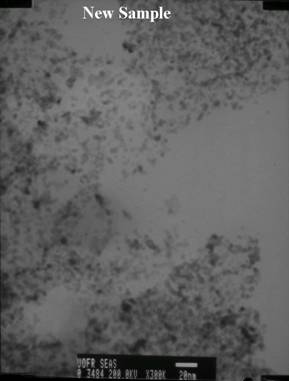
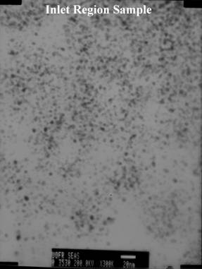
Figure 13. New
electrode microtome section compared to sample taken from the cathode inlet region
of a water-clearing fuel cell that underwent catalytic heating. (300,000x)
Figures 12 and 13 show some
high magnification TEM images of 100 nm microtome sections of the
electrode. The dark spots correspond to
the dispersed catalyst. It is apparent
from these figures that several large particles appear in the inlet region
samples; however the vast majority of the catalyst appears to be dispersed with
no significant ripening.
•
Using light microscopy, sputter coating,
SE, In-lens SE, microtomy, and TEM, internal fuel cells structures were
examined.
•
Massive damage to backing layer and
electrode was observed in water-trapping fuel cell at flow-field channel
locations that accumulate bulk liquid water.
Freezing of this water damages internal fuel cell components.
–
Crushed or broken backing layer fibers
–
Electrode cracking and de-lamination from
membrane
•
Minor damage to backing layer fibers in
wet outlet region of water-clearing fuel cell was observed.
•
Large scale cracking was observed on the
MEA electrode of water-clearing fuel cell following repeated cold start events.
–
No damage observed in fine pore structure
of electrode or micro-porous layers in even the wettest region of water-clearing
fuel cell.
•
No excessive sintering or ripening of
catalyst observed in fuel cell that underwent catalytic heating to assist cold
starting.
Acknowledgements
I would like to thank Brian
McIntyre for his assistance throughout this project. I also wish to thank General Motors Fuel Cell
Activities for providing me the opportunity to perform this study.