Electron Microscopy
of Polymer Cholesteric Liquid Crystal Flakes
![]()
Cathy Fromen
Department of Chemical Engineering
catherine.fromen@rochester.edu
Final Project, Optics
307
Spring 2009
|
Introduction 1.
Abstract 3.
PCLC Flakes |
Experimental
Procedure |
Results
and Discussion |
Conclusions
1.
Conclusion 3.
References 4.
Comments |
Introduction
Polymer Cholesteric Liquid
Crystals (PCLCs) exhibit advantageous optical and electrical properties, making
them useful for display technologies.
PCLCs reflect wavelengths proportional to the cholesteric pitch length and also exhibit motion when suspended in a host fluid:
translation due to electrophoresis and reorientation due to Maxwell-Wagner
polarization. Recent studies have shown
that internal flake doping or flake layering can reduced
the electric field required for such motion.1-2 Uniformly doped PCLC flakes were created by
adding 10% carbon black (wt%) to PCLCs prior to alignment and layered PCLC
flakes were created by spin-coating a thin film of PCLC with a conductive layer
of Poly(3,4-ethylenedioxythiophene), also known as PEDOT. In this project, PCLC flake doping and
layering was investigated using electron
microscopy. Electron micrographs of undoped PCLC flakes were obtained
and a distinct fingerprint texture was found on the surface. Spin-coated layers of PEDOT on PCLC flakes were found to have a similar fingerprint structure, and the
PEDOT layers were found to be approximately 1um thick. Uniformly doped carbon black flakes did not
exhibit the fingerprint structure, but a less organized wrinkled sheet texture was found. This was determined
to be due to the distribution of carbon black conglomerates, which vary in size
from a few nanometers to as large as 500nms.
The term “liquid crystal”
refers to phase of matter, also called a mesophase, with structural properties
between those of crystals and liquids.
Liquid crystals (LCs) have long-range
orientation order, as in a crystalline structure, but the molecules themselves
are often anisotropic, resulting in a degree of order found between the two
phases.3 There are two different classes of liquid
crystals: lyotropic and thermotropic.
Lyotropic materials are found in solution and enter the mesogen phase at a particular concentration. Thermotropic materials enter the liquid crystal
phase between a certain temperature range, beginning
at the crystalline melting point.
Thermotropic liquid crystals are then divided
into different categories based on their internal order. These categories include the nematic,
cholesteric and smectic phases. The
nematic is the simplest and possesses long-range orientational order defined by
a director n, but is completely
anisotropic in other directions. The
smectic phase is more complex, where the structure is not
only defined by long-range orientational order, but the presence of
internal layers results in weak translational order as well. The particular liquid crystals discussed in
this project fall into the chiral or cholesteric
phase. In this phase, the director n, which is the unit vector describing
the average direction of orientation along the long axis of the structure,
rotates 360˚ throughout the material to form a helix.
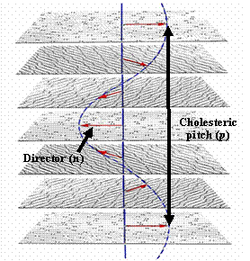
This
helix can be described by a pitch length, P, which is the length required for a complete 360˚ rotation of
n.
As a result of the internal alignment of the
liquid crystals, the material exhibits a selective reflection effect. The PCLCs in this project align in a
left-handed helix; due to the selective reflection effect
left-handed light will be completely transmitted through the material, while
right-handed light at a specific wavelength of λ0 will be
reflected. λ0
is the wavelength of selective reflection and is equal to the refractive index
of the material, nav,
multiplied by P, the
pitch length.4
This project expands on
previous work done with polymer cholesteric liquid crystals (PCLCs). As the name implies, PCLCs are thermotropic
materials that can exist in the cholesteric phase. PCLCs differ from
typical cholesteric liquid crystals due to the large size of the molecules
themselves, which are in fact polymers.
As a result, the order obtained in the LC phase can be
maintained below the melting temperature because the large polymer
molecules are “frozen” into place. Thus,
PCLCs can exist with optical and electrical liquid crystal properties at a
temperature below the melting point. The
specific PCLCs in this project are noncrosslinkable
cyclic polysiloxanes substituted with mesogenic groups which are
connected to the backbone by aliphatic spacers.
The colors are supplied by the manufacturer and
they differ in ratios of chiral to nonchiral side chains, thereby changing the pitch
length. As a result, PCLC technology has
the ability to result in selective reflection across the visible light
spectrum.
In order to utilize these
optical properties on a micro scale, PCLC “flakes” were made. Shaped PCLC flakes were
made by casting a thin film of PCLC material into a mold. Using soft lithography, a mold was made of polydimethylsiloxane (PDMS) with 60µm x 20µm wells. Solid PCLC material was
heated into the LC phase, occurring above 50˚C, and was then
aligned into a thin film onto using a shearing force. This thin film of PCLC was
spread across the PDMS mold, producing aligned PCLCs in the individual
wells. The material was
then cooled below its melting point, where the LC alignment was
maintained. The PCLC flakes are then removed from the mold by laminating the thin film
onto a glass substrate, from which the flakes can be easily removed and
suspended in a host fluid.5
The specific electrical
properties of these PCLC flakes have been studied in
detail in previous projects.1 The PCLC flakes are known to exhibit various
types of motion, including reorientation and translation. In reorientation, the PCLC flake rotates 90˚
along their long axis to align with the applied electric field. As a result of the
PCLC flake’s dimensions, reorientation changes the PCLC flake from a position
where it reflects light back to the viewer, to a position where the reflected
light cannot be seen by the viewer.
Reorientation occurs from Maxwell-Wagner polarization in an AC field,
which describes the induced dipole resulting from an electric field’s effects
on the interface of two materials with dissimilar dielectric properties. The second type of motion exhibited by PCLC
flakes is translation, occurring in a DC field.
Translation is driven by electrophoresis; due
to interfacial charging, the electric field creates a double layer around the
now charged PCLC flake and this fluid motion causes the flake to move. Both types of motion, translation and
reorientation, have possible applications for display technology.
PCLC flake technology has
the potential to make a huge impact in the reflective particle display
industry. This industry is expected to make huge strides in the near future, with
products such as the Amazon Kindle already a commercial success. However, there are many obstacles still
facing current reflective particle displays.
In particular, current particle display technologies lack the ability
for a full color display. E-Ink, used in
the Kindle, only has potential for a two-color display without the application
of color filters. Due to the selective
reflection effect, PCLC flake technology can offer brilliant colors over the
full visible spectrum. However, PCLC
flake technology also has major obstacles to overcome: higher power
requirements, 50% reflected light loss and microencapsulation challenges. Recent advances have occurred in microencapsulation of
PCLC flakes, offering potential to apply the technology to a flexible
application, as well as advances in flake doping to further
lower the power requirements for flake motion.
In order to increase the
conductivity of individual flakes, methods of flake doping has
been explored. Various types of
carbon black was dispersed in the PCLC material before aligning in the LC
phase, and it was found that uniform doping can increase the conductivity of
the PCLC flakes. 1 This
allows a dramatic drop in translation and reorientation times. Flake layering has also resulted in increased
flake conductivities. Recently
procedures have been developed for creating two layer
PCLC flakes, using combinations of different colored PCLCs, with a conductive
polymer, PEDOT. These novel doping
methods can increase the viability of the technology by decreasing the required
energy input.
The purpose of this
project is to utilize electron microscopy to explore further PCLC technology
and the effects of flake doping and layering.
The self-assembly of the cholesteric liquid crystals results in
interesting flake surface features, which were able to be resolved by both the
SEM and the TEM. The effects on this
liquid crystalline structure due to the addition of dopant
or a conductive layer were also studied. In addition, the distribution of the carbon
black dopant in doped PCLC flakes was
observed, as well as resulting thickness of PEDOT layers on the flakes.
Experimental Procedure
Three types of flake
samples were observed in this project: neat undoped PCLC flakes, 10% carbon black doped flakes and two
layered PCLCs with a PEDOT layer. Shaped
flakes were prepared in a PDMS mold and were laminated
to a microscope slide. They were then removed from the slide and attached to an SEM pin using
carbon tape, or applied directly to a lacey carbon TEM grid. Due to the insulating properties of the PCLC
material, the SEM pins were then coated with
gold. Coating is a crucial step in
observing the PCLC flakes; it provides a conductive path for the electrons to
follow to ground, which eliminates effects of charging, it increases the
emission of secondary electrons, the prime focus in this project, and it
increases the stability of the polymer sample, which might otherwise deteriorate
in the beam. A gold sputter-coater found
in room 216 in Wilmont Hall was used for 30 seconds
at 15mamps, resulting in a coating of approximately 3nm. Also viewed in this project was a thin film
of carbon black. Carbon black was
dissolved in methylene chloride,
the same solved used to dissolve the solid PCLC material prior to alignment,
and was then deposited directly to an SEM pin.
The instruments used in this project were the Zeiss-Supra
40VP SEM and the FEI Tecnai F20 TEM found in room 216
in Wilmont Hall at the
Results and Discussion
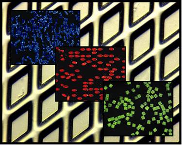
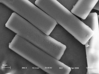
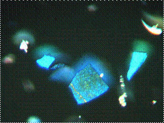
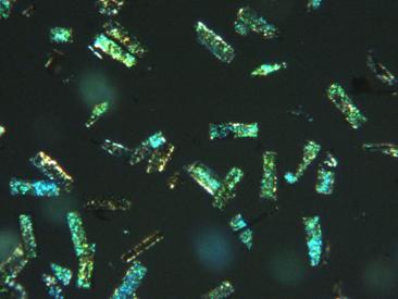
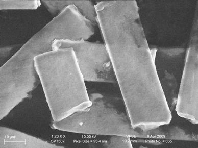
PCLC flakes have
traditionally been viewed using light microscopy. The selective reflection effect results in
PCLCs appearing a brilliant color. Below
are two images of neat undoped PCLC flakes of various
colors and shapes. Rectangular flakes
are 20x60μms.


PCLC
flakes can be easily viewed using traditional light microscopy: image on the
left shows PCLC flakes in a PDMS mold, while image on the left shows different
varieties of shaped flakes covering a range of colors, with the background
image showing an empty PDMS mold.
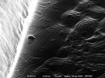
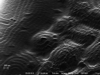
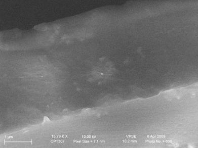
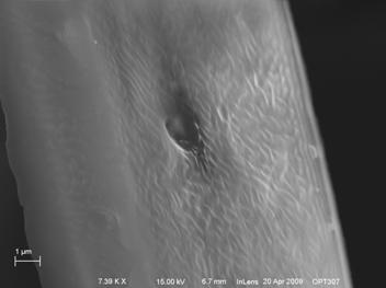
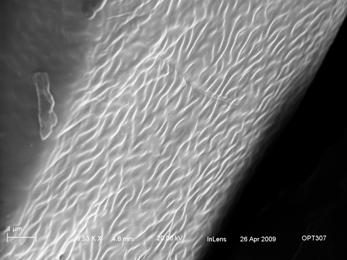
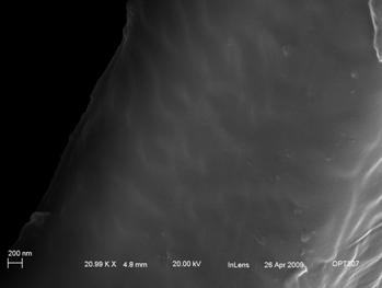
While light microscopy can
accurately capture the selective reflection, electron microscopy is required to
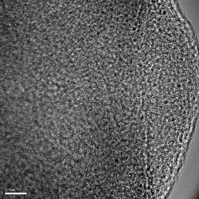
resolve much smaller features of the liquid crystalline structure. In this project, the secondary electron
detectors were used to resolve surface features of the
PCLC flakes. Both the SE2 detector and
the InLens detector were able to resolve surface
features of the PCLC flake. These
micrographs show a Fingerprint Texture, indicated by dark lines outlining a
spiral structure. 4 These
“wormy” lines are spaced apart approximately half the pitch length of the material. These particular flakes exhibit selective
reflection in the green, which would result in a theoretical pitch length
around 360nm. When measured using the ImageJ software6,
these bands are approximately 200nm apart, as compared to the expected
theoretical value of 180nm. These
surface features are best resolved using the InLens
detector at short working distances, which maximizes the secondary electrons
returned back towards the beam.
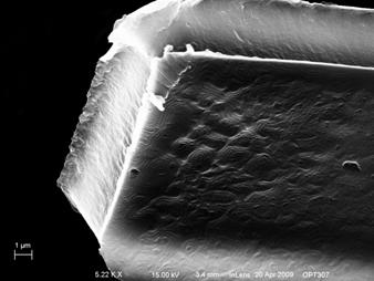
SE2
Micrographs:

SE2 micrographs of neat undoped PCLC flakes of increasing magnification
InLens
Micrographs:

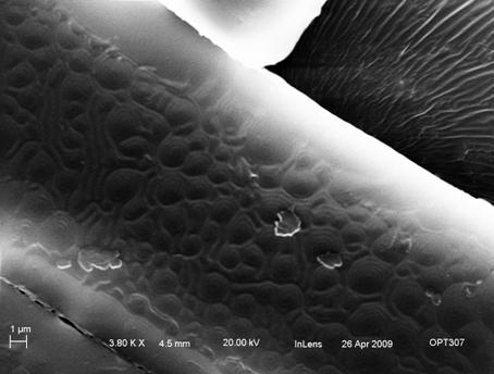
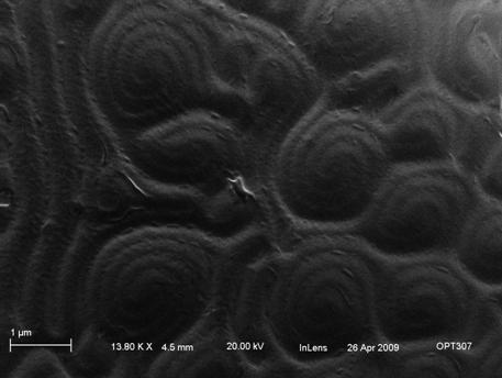
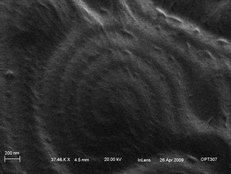
InLens micrographs of neat undoped PCLC flakes of
increasing magnification. Surface
fingerprint texture of PCLCs found yielding “wormy” lines separated by
approximately 200nm
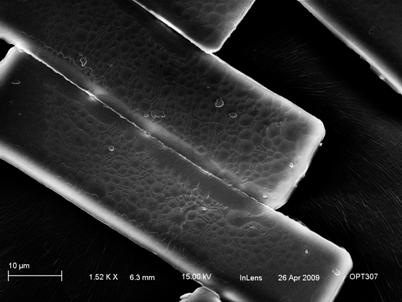
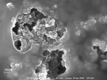
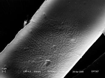
2. Two Layered PCLC
Flakes with PEDOT Layer
Two layered flakes have
also been viewed using light microscopy.
However, PEDOT exhibits high transmission in the visible light range,
resulting in a completely clear polymer coating. Light microscopy is unable to resolve any
specific features of the PEDOT layer, and images look identical to neat undoped PCLC flakes.
Light Microscopy image of PEDOT
coated PCLC flakes
The secondary electron
detectors were used to examine the effect of layering
PCLC flakes with PEDOT. Again the surface features of the flakes were resolved using
primarily the InLens detector. These micrographs show the same Fingerprint
texture as seen in the undoped PCLC flakes, even
through the PEDOT layer. However, unlike
in the undoped PCLC flakes, the spiral structures are raised by a few nanometers and appear only close to the
sides of the flakes. Towards the center
of the flakes, the flow pattern of the PEDOT becomes very apparent, resulting
in a much less coherent spiral structure, until the spiral structure is
unrecognizable at all.
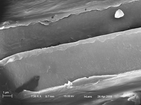
InLens micrographs of the surface features of two layer PEDOT coated flakes.
Micrograph on the left shows PEDOT coating with surface features
resolved. These surface features are magnified in the following two images, yielding the
traditional fingerprint texture, as well as the raised fingerprint and flow
patters on the far right.
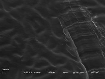
Micrographs of the PEDOT
coated PCLC flakes were also used to characterize the
PEDOT layer, which ranges from 400nm to 1.5μm in thickness.6
InLens micrographs of the side of two PEDOT coated PCLC
flakes: PEDOT layer found on top side of both flakes, ranging from 400-700nm in
thickness
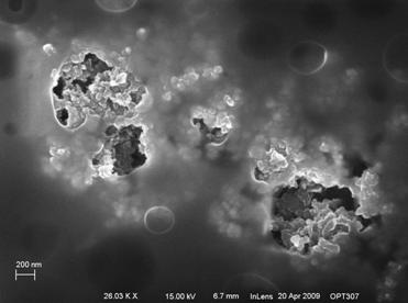
3. Uniformly Doped PCLC Flakes
with 10% Carbon Black
Uniformly doped PCLC flakes with 10%
carbon black were also viewed first using light microscopy. While similar in appearance to undoped PCLC flakes, the addition of the carbon black
yields regions within the flake that absorb light and appear black to the
viewer at a high magnification. Recent
studies and tests on flake conductivity have brought into question the
uniformity of the carbon black doping, and one of the main goals of this
project was to study the distribution of carbon black in the flakes. From the following image, it is apparent that
light microscopy could not accomplish this goal alone.
Uniformly doped PCLC flakes
containing 10% Carbon black (wt%). Flakes are 20x60μm in dimension.
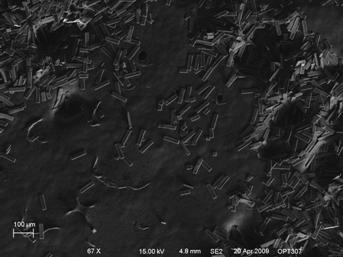
In order to study the
distribution of the carbon black within the PCLC flakes, many different
techniques were employed. First, it was hoped that due to the increase
in flake conductivity, carbon black doped flakes could be viewed without the
gold surface coating. However, charging
occurred quite rapidly. Uncoated flakes were then viewed using the variable pressure option in the
SEM. Leaking air into the tank and using
the VPSE detector dramatically improves the quality of the images obtained, but
lowers the ability for high resolution, as apparent in the following images.
Variable Pressure
Micrographs
Electron
Micrographs of 10% carbon black doped PCLC flakes viewed using variable
pressure of 30Pa
As a result of the poor resolution, all future samples were
coated with gold to avoid charging.
To assist in the search for carbon black within the
PCLC flakes, a film of carbon black was deposited
directly to a SEM pin, allowing for characterization of carbon black structures
outside of the PCLC film. This film
yielded interesting results; the micrographs reveal that carbon black tends to
conglomerate into a few distinct dimensions.
The smallest particle size able to be resolved yielded carbon black
conglomerates on the order of 10-50nm. However, these small conglomerates were then easily found in larger structures ranging from
150nm to a few microns. These
micrographs were important in identifying carbon black conglomerations in the
following flake samples.
Image of Carbon Black
Film
InLens
micrographs of carbon black film. Top
two micrographs show large carbon black conglomerations, while bottom two
micrographs show organization into 100-200nm spherical structures.
Following analysis of the carbon black
film, the surface features of the doped carbon black flakes were then viewed
using the SEM. Immediately, a noticeably
different surface structure as compared to the neat undoped
PCLC flakes becomes apparently. In the
neat undoped PCLC flakes, the surface yielded the
distinct fingerprint pattern. With the
10% doped PCLC flakes, there is no defined spiral structure, but rather a wavy
lined pattern similar to a wrinkled sheet.
It appears as though the fingerprint pattern was
disrupted by the addition of the carbon black, forming less organized
surface structures, and presumably less internal order as well. The wrinkled sheet pattern still contains the
“wormy” lines mentioned before, with spacing still approximately 200nms. However, the loss of the tight fingerprint
spiral is indicative of a change in organization. Also of note, the wrinkled sheet seems to
exits on both the top and bottom surfaces of the flakes and on the sides as
well. Surfaces with damage from the
sheering process yield the wrinkled sheet as frequently as surfaces lacking the
sheer damage, and no surfaces were viewed without the
wrinkled sheet pattern.
Secondary
Electron Micrographs

InLens electron
micrographs of 10% carbon black doped PCLC flakes. The wrinkled sheet texture is apparent in all
six samples, showing a wide variety of flake angles.
While these secondary electron images only
reveal information about surface topology, much can be
inferred about the internal structure as well. As mentioned, one of the main goals of this
project was to explore the uniformity of the carbon black doping within the PCLC
flake. Recent conductivity tests had
shown discrepancies between aligned films of PCLCs doped with carbon black
versus an unaligned mixture of the two components. It was thought that
the sheering processes separated the PCLC and the carbon black, isolating the
carbon black from the surface of the flake and altering the conductivity of the
flake. However, the electron micrographs
obtained for this project suggest this is not the case. Taking the top right micrograph from the
previous section, large conglomerations of carbon black can be located directly
on the surface of the flake. These
conglomerations are circled below, shown alongside the
original image. Unfortunately, from only
the secondary electron micrographs it is impossible to determine completely if
these conglomerations are carbon black or merely PCLC impurities. However, while impurities in the PCLC
structure were seen in the neat undoped
PCLC flakes, found to be typically less than 100nms (see above), the impurities
here are generally larger, typically around 500nms. Also, their
strategic placement seems to correspond to alterations in the wrinkled sheet
pattern and are most likely responsible for the absence of the fingerprint
texture. Both the x-ray detector and the
backscattered electron detector were employed to
distinguish any difference between these impurities and the remaining PCLC
material. It was hoped
that the polysiloxanes making up the PCLCs would
result in different x-ray or backscattered electron signals compared to the
carbon black. However, the PCLCs are
also comprised of mesogen liquid crystal groups in
which carbon is the main constituent. As
a result, neither detector was able to distinguish any additional information
regarding these impurities.

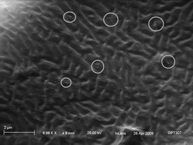
InLens electron
micrographs of wrinkled sheet texture in 10% carbon black doped PCLC
flakes. On left is unaltered micrograph,
on right impurities determined to be carbon black have been circled
Finally, TEM micrographs of the
uniformly doped PCLC flakes were obtained. Flakes were placed
onto a TEM carbon grid, and the side regions of the flakes were imaged. This was done
because the center regions of the flakes were too thick to allow for
transmission, but variations in the side morphology allowed for imaging of
thinner regions of the flakes. These TEM
images support conclusions drawn previously by the SEM analysis. Carbon black conglomerates of various sizes were found distributed throughout the samples, varying from
as large as 200μm, to a few hundred nanometers, to tens of nanometers and
possibly smaller.
TEM
Images
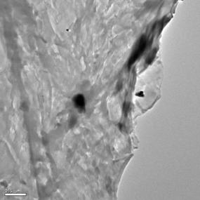
TEM images
of 10% carbon black doped PCLC flakes.
Carbon black conglomerates of decreasing size shown from left to right.
Conclusions
and Acknowledgements
In this project, the surface features and liquid crystalline order was explored using electron microscopy. Neat PCLC flakes were characterized and a distinct fingerprint texture was revealed. A slight variation of this fingerprint texture was found in the layered PEDOT coated PCLC flakes, but was completely absent in the uniformly doped 10% carbon black flakes. Looking into this structural various, it was concluded that the distribution of carbon black conglomerates throughout the sample was responsible for the alteration. Further work with higher concentrations of carbon black doping might yield more definite results.
Thanks to Jerry Cox, Ken
Marshall, Dr. Stephen Jacobs and the Laboratory for Laser Energetics
for introducing me to PCLC, the loves of my academic life.
Special thanks to Brian
McIntyre for all of his patience,
assistance, excellent ideas, support and teaching prowess; without his help
none of this project would ever have been accomplished.
And thanks to MF, the HTML
Master.
1) Kosc,
T. Z., Motion of Polymer Cholesteric Liquid Crystal Flakes in an Electric Field. PhD Thesis,
2) G.
Cox and C. Fromen, PEDOT flake layering, internal report, 8-2008.
3) Hamley,
I.W. Introduction to Soft Matter.
4) S. Jacobs, Optics and Liquid Crystals for Chemical
Engineers, class notes CHE 447/MSC 434, Spring
2009.
5) G. Cox, Microencapsulation effect – standard
cell type, internal report, 6-3-2008.
6) ImageJ
software, version 1.41 for Windows, downloaded from http://rsbweb.nih.gov/ij/download.html
on March 23, 2009.
![]()
Cathy Fromen, April 2009