Investigation of Magnetic Recordings Made Throughout History
Ben Ecker
beckerpas@gmail.comUniversity of Rochester
Department of Physics and Astronomy
Introduction
Samples
The common theme of the samples were that they are all magnetic recordings made throughout history, which included a (potential) meteorite shard, a floppy disk, a zip drive disk, and a hard disk. The Campo del Cielo meteorite shard originated from a region in Argentina and was expected to have made impact approximately four to five thousand years ago, it was acquired from geological sample vendor and was expected to be authentic. It turns out, that meteorites are an incredibly useful tool for the paleomagnetism community as it allows them to look back to a fixed moment in time. When the meteorite makes impact, the shards undergo tremendous heating and stress allowing for the magnetic domains to interact with the earth’s current magnetic field before cooling back down and becoming fixed. The floppy disk and zip drive disk are both information storages devices that encoded information into magnetic domains, and they used similar technologies that allowed them to be relatively inexpensive information storage devices that could be transported between locations. The devices main component is a thin circular Mylar section that has a magnetic coating where the information is stored, the main difference between the two types of disks are their section sizes and domain size where the smaller domains allow for high information storage. Unfortunately the technology that allowed them to be so inexpensive came at the cost of capacity, and largely fell out of fashion by the mid-2000s. A similar information storage device to the floppy and zip disk is the hard disk drive, and operates under similar principals to the floppy and zip disk. The technology has been further refined to where a magnetic coating is placed on circular aluminum platters, and they have become the prevailing secondary storage devices for general purpose computers. Lastly, a read-write head of hard disk drive was also examined.
Methods
-
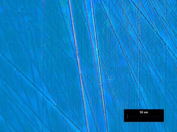
Light Microscopy
Sample were often viewed under a light microscope initially to ensure proper sample preparations before placing into the AFM or SEM and wasting valuable instrument time.
-
Sample Preparation - Polishing
The meteorite shard was naturally rough and required extensive polishing before viewing. Sequential polishes on a polishing wheel with silicon carbide grinding sheets were performed starting at grit sizes (average grit size in microns) 300 (30), 800 (12), and 1200 (2.5).
-
Sample Preparation – Etching
It turned out that meteorite was initially rather dull and the main surface features were just the polishing lines. To see the material grain sizes, the shard was placed in a Nital solution for about a minute, a mixture of nitric acid and alcohol. Extreme care was used due to the volatility of the solution. -
Sample Preparation – Conductive Coating
The floppy disks were partly made of Mylar, which is insulating, and to prevent any potential charging effects when viewing the samples in the SEM, the samples were coated with a thin layer of gold using a Denton Sputtering system. Proper groundings to the samples were also added with the use of conductive carbon paint. -
Atomic Force Microscopy
Extensive AFM was performed before attempting MFM to determine sample surface morphology. This would have greatly helped if the tips had not been broken in that it would have allowed me to see if the tip was seeing the surface correctly with the first pass. There was the potential for the first pass to become severely distorted due to both the surface and magnetic interactions. AFM offered a way to look at the surface roughness and verticality, which the SEM is often unable to provide easily.
-
Scanning Electron Microscopy – SE2, Inlens, BSD
The SEM with appropriate viewing parameters offers superior visualization of the surface morphology compared to AFM, and potentially useful secondary information. Care was taken to ensure the samples were firmly secure to protect the instrument from any possible magnetic interactions before being placed into the Zeiss Auriga SEM.
-
Energy Dispersive X-ray Spectroscopy – X-ray collection, and Mappings
EDX allows for the determination of sample elemental composition, and when mapping, spatial variations in elemental compositions can be seen.
Results & Discussions
Due to changes
in the project direction midway, I ended up collecting
a tremendous of data and images. Some were good images and some were
pretty
awful images. For
brevity’s sake, I am
only displaying a collection of images from each sample that I believe
best
represent the sample while still allowing for comparisons between the
different
sample surfaces. Most
of the samples
have an SEM images taken at a lower magnification (1kX) to see large
surface
morphology and an SEM image taken at a higher magnification (10kX) to
see the
coatings/grain surface morphologies.
AFM
measurements are usually presented for 30umx30um and 2umx2um scale with
both 2D
and 3D perspectives. Lastly,
I tried to incorporate
one or two additional bits of information that I believe were
noteworthy or
interesting.
Pre-Etched Meteorite Shard
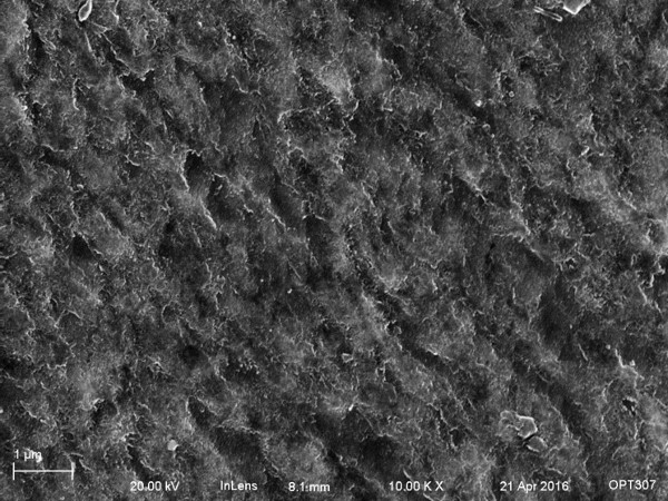
SEM: In the pre-etched SEM images shown below, the main surface streaks were related to the polishing. The large clumps are most likely dust and polishing debris not properly removed before imaging. You can clearly make out polishing streaks going in two different direction, which is due to lack of prior knowledge polishing on behalf. During polishing, I rotated the shard to get a better grip on it with respect to the wheel changing the direction of the polishing pattern.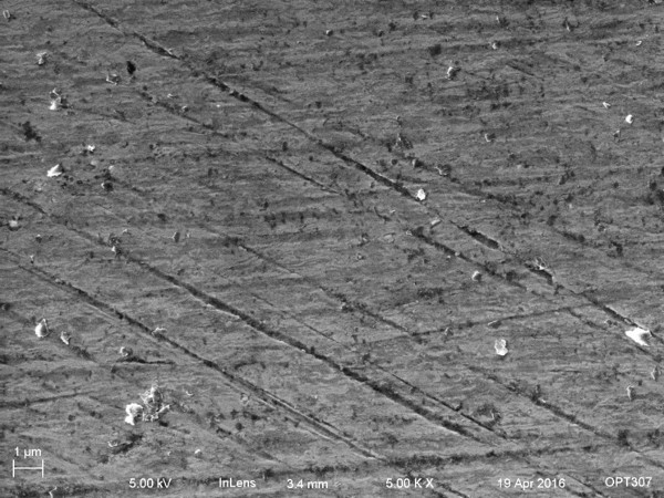
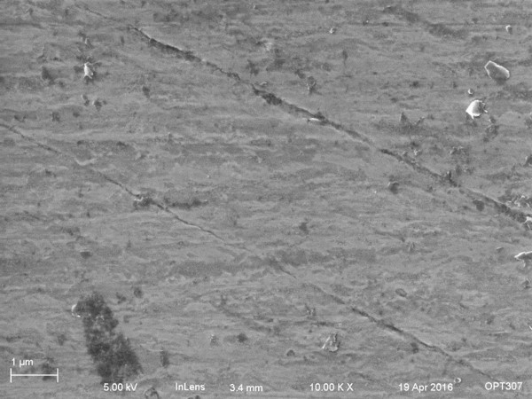
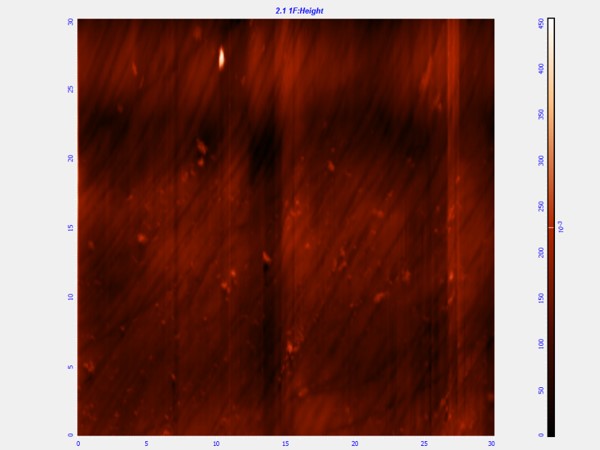
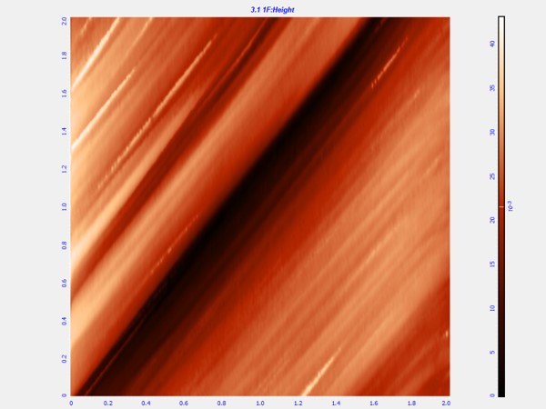
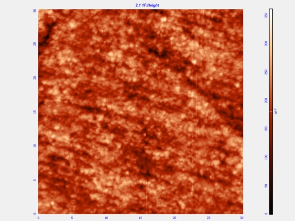
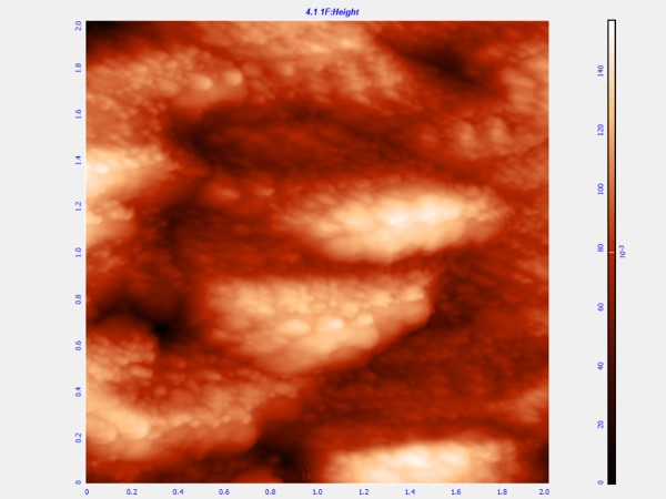
| Sample Scan Size |
Root Mean Square (um) |
| Pre-Etched 30umx30um |
0.0259 |
| Pre-Etched 2umx2um |
0.00804 |
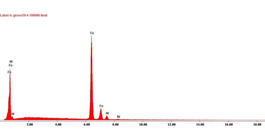
EDX Spectrum: The only elements visible in the characteristic x-ray spectrum is iron and nickel, which is a strong suggestion that the elemental composition is similar to verified meteorites.
Post-Etched Meteorite Shard
SEM: After the Nital etching process, the meteorite shard's polishing streaks are sufficiently suppressed and the grains become easily visible. The surface is now remarkably patterned in a rough pattern reminiscent of sea waves.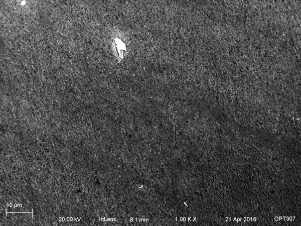
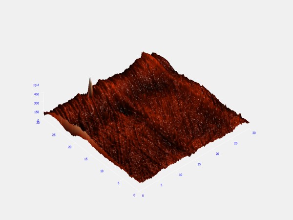
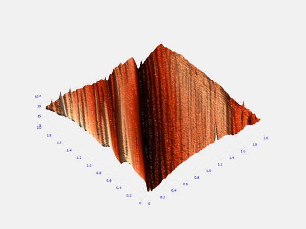
AFM: The AFM very easily is able to resolve the etched shards roughness and is able to pick up the rolling up and down features of the grains. The sample roughness for both scans has gone up a reasonable amount compared to the pre-etched shard.
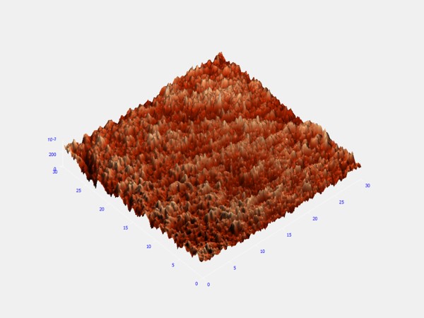
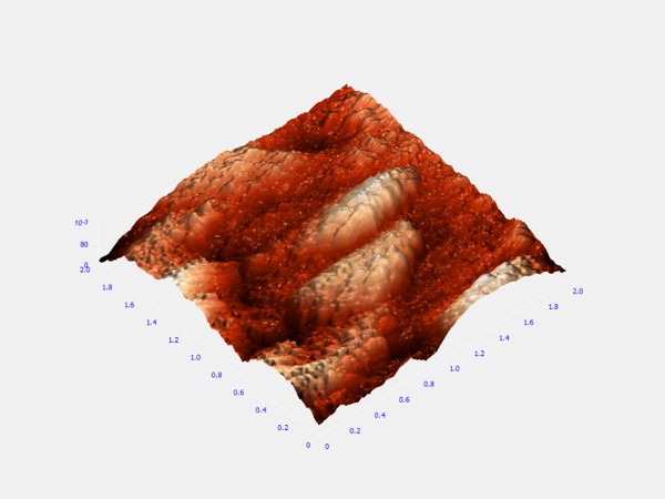
| Sample Scan Size |
Root Mean Square (um) |
| Post-Etched 30umx30um |
0.0363 |
| Post-Etched 2umx2um |
0.0248 |
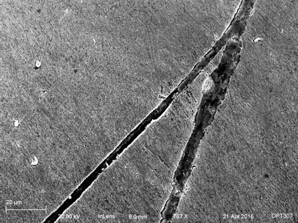
EDX Mapping: It was my hope that by etching the shard, the grain boundaries would display some variations of elemental composition. Unfortunately, nital does not etch based off of elemental composition but instead by the grains phase orientation. Thus the EDX mapping of the grains proved not useful. Afterward, I tried taking an EDX mapping of a crack in the sample. The first EDX map is of iron and the second is of nickel. From the mappings, it is clear that the crack is deficient in iron, and the nickel is pretty uniformly spread out.


Floppy Disk
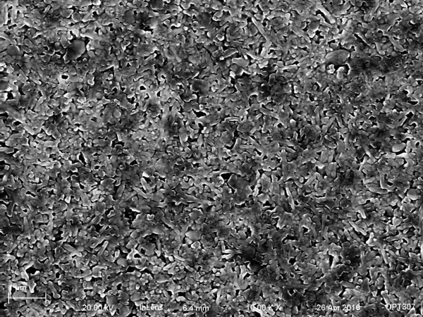
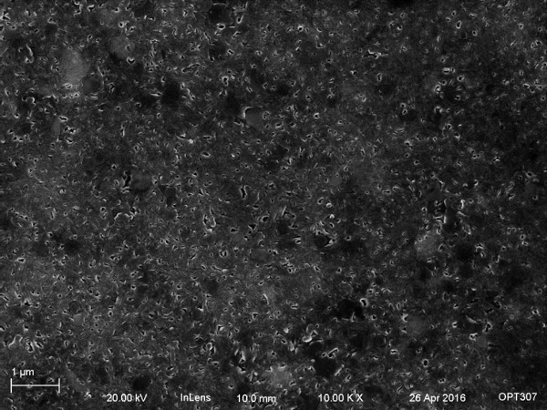
SEM: The SEM images of he floppy disk disply the spindly structures made by the magnetic coating on the mylar sheet. There are regions of bright and dark spots in both SE2 and Inlens detector images, at both high and low accelerating voltages. EDAX mappings also provided little in the way of determining the variations in images. As best as I can reason, the surface is not as flat as it appears from the AFM images. Instead of flat the surface is forming mountaints and valleys and some of the escaping electrons are being blocked from reaching the detectors leading to regions of dark and bright. It should also be noted that the bright edge effect is clearly visible in the second image, indicating an exposed surface. These features are stationary indicating that it is not a charging pattern.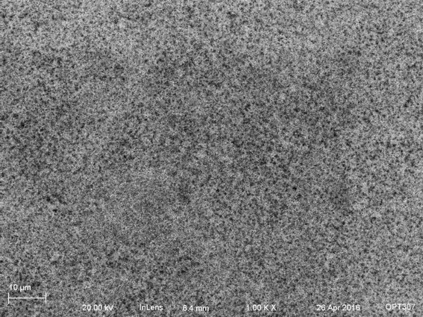
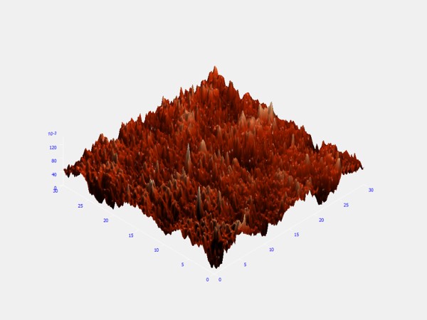
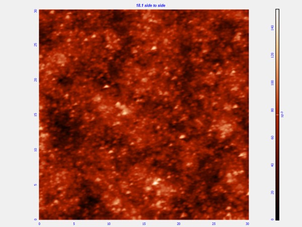
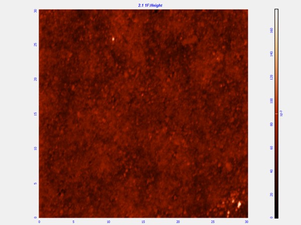
AFM: The AFM picture further confirm the mountain and valley theory, which are clearly visible in the 2umx2um image. It again appears that the tip was striking the surface a bit to hard leading to the streaking image shown in the 2um image. Lastly below the roughness measurements, are two 30umx30um images of the similar areas. The left image was scanned top to bottom, while the right image was scanned left to right. The bright spot orientation appear to change their shape depending on the scan direction, indicating that there was most likely something wrong with the tip, perhaps it picked something up on one side leading to distorted scans.
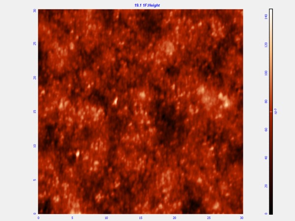
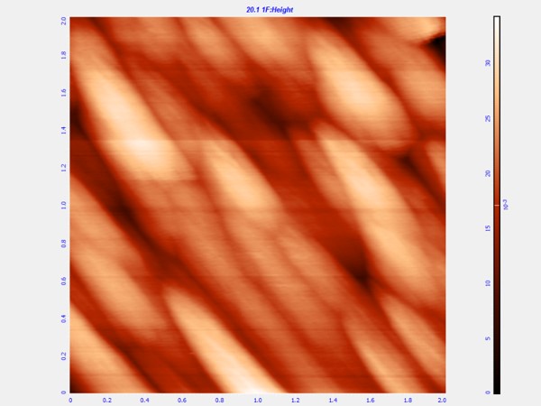
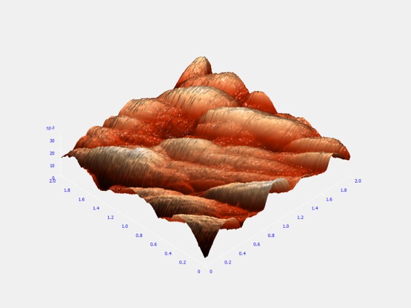
| Sample Scan Size |
Root Mean Square (um) |
| Floppy 30umx30um |
0.0153 |
| Floppy 2umx2um |
0.00454 |
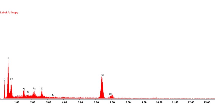
EDX Spectrum: The EDX spectrum shows that the floppy disk was coated with a predominately iron oxide, with perhaps a bit of cobalt and chlorine.
Zip Disk
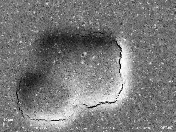
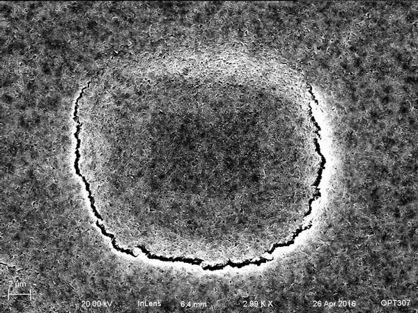
SEM: The zip disk sem images again show a spindly pattern on the surface, and they also display the dark and bright regions. This is most likely due to how the surface coatings are deposited since the processes are similar for both zip and floppy disks. The edge effect is particular visible in the 10kX magnification, and this again is not due to charging.. I also included images of the samples after taking a full EDX mapping of the bright and dark spots. The zip disk post EDX image is on the left and the floppy disk post EDX image is on the right. It is very easy to see the rip in surface exposing the insulating mylar films underneath. What was so remarkable about these photos, is that the damage was not occuring where the beam was striking the surface, but instead further away. The floppy disk image in particular even shows the carbon deposit from the beam showing very clearly where the mapping took place, yet the damage occured some distance away.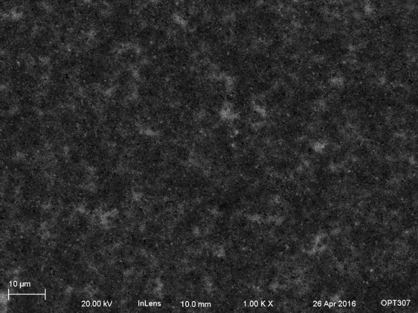
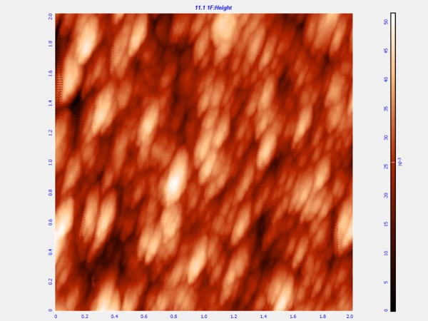
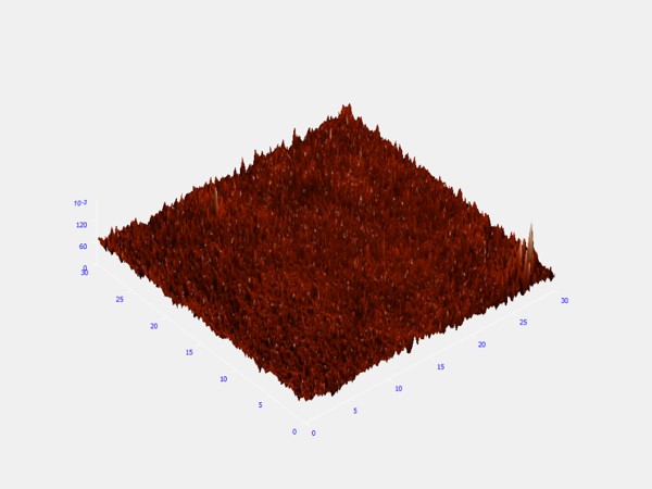
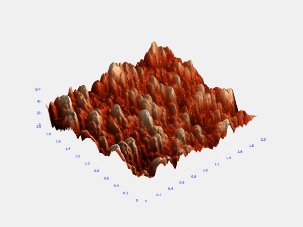
| Sample Scan Size |
Root Mean Square (um) |
| Zip 30umx30um |
0.00982 |
| Zip 2umx2um |
0.00701 |
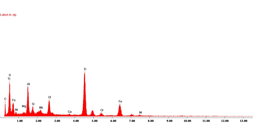
EDX Spectrum: The EDX spectrum for the zip disk is particulary puzzling. It appears to have another magnetic iron oxide coating, but it also features paramagnetic titanium. I was unable to find any work suggesting the presence of titanium, but I was also not able to verify the coating used on zip disks. What I do know is that the zip disk's magnetic coating was able to increase the storage capacity by about a factor of 10.
Hard Disk
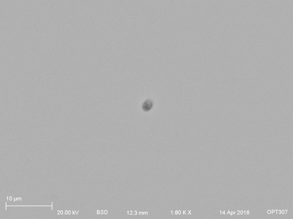
SEM: The hard disk was particulary difficult to collect SEM images of, due to the incredibly smooth surface, there was just very little topologically going on. So secondary electron detectors were unable to pick up much of anything. There is also a backscattered detector image featuring a bit of dirt for contrast shown below, but it was also fairly dull of an image.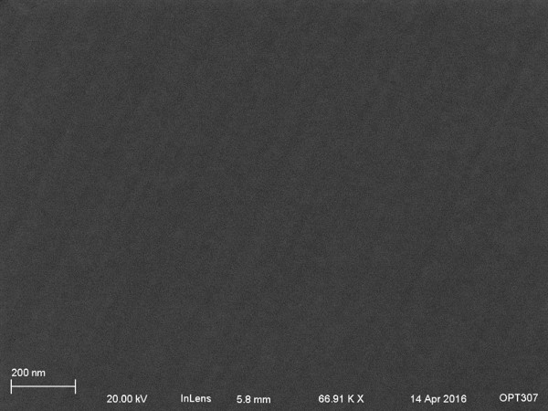
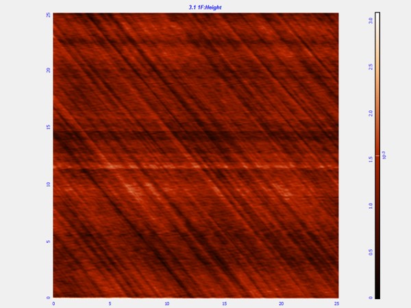
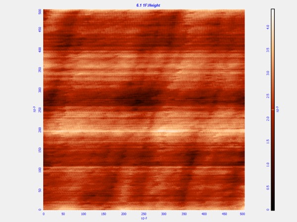
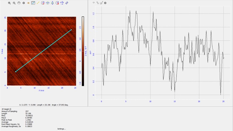
AFM: The AFM was able to clearly pick up streaking patterns across the surface. While the scratches are incredibly small ~0.5 nm, shown by the surface roughness calculation and sectional analysis, it is likely damage caused by the head which lead to the crashing of the hard disk. Even this small variation likely lead to the disk failing, which is how I managed to obtain a piece of one.

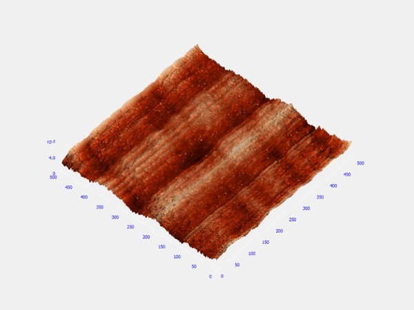
| Sample Scan Size |
Root Mean Square (um) |
| Hard Disk 25umx25um |
0.000258 |
| Hard Disk 0.5umx0.5um |
0.000523 |
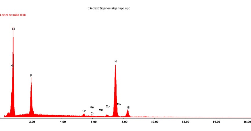
EDX Spectrum: The EDX spectrum for the hard disk clearly shows peaks for cobalt, nickel, and phosphorus. The magnetic coating for hard disk are usually an outermost 5um layer of cobalt, with a 20 um layer of nickel phosphorous. The platter is mainly aluminum with a bit of magnesium, but the core of the platter is covered by too much magnetic coating to see any characteristic xrays. The phosphorus was being used to make the nickel nonmagnetic, and perhaps the titanium and chlorine was being used in the zip disk in a similar fashion.
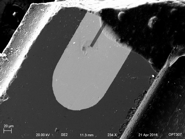
Read-Write Hard Disk Head
SEM: Lastly, images of the read-write head of the solid disk were imaged in the SEM. The image on the left shows the entire cross section of one such head, where the contact is the visibly bright area on the left of the image. The middle section of the image is another magnetic coating using to read the magnetic field of the disk. The right images shows the magnetic coating.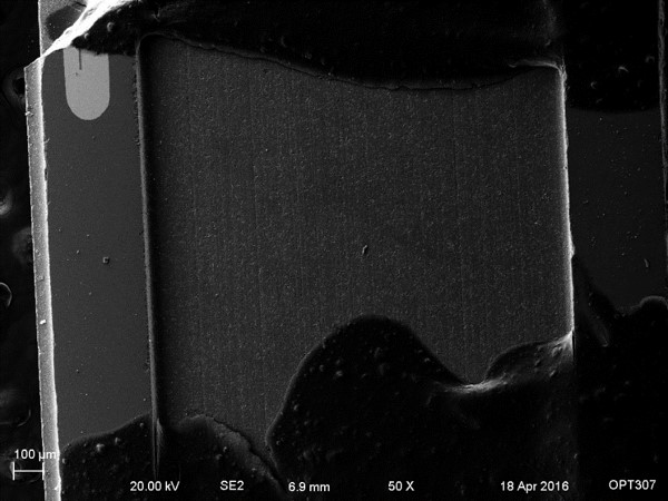
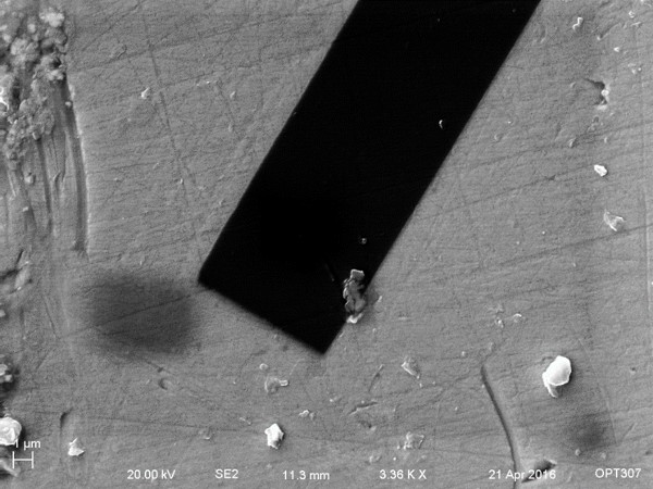
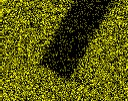
EDX Mapping & SEM Position: EDX mapping were taken of the contact shown in the above image. The first two images show the contact position and the SEM image of the spot where the mapping was taken. The mapping shown below correspond to oxygen, lead, aluminum, magnesium, iron, and silicon going from left to right. The black contact clearly contains oxygen, magnesium, and iron, while it is deficient in lead, aluminum, and silicon.


All Atomic Force Microscopy Roughness Comparison
The atomic force microscope software program was able to calculate the surface roughness of the scanned regions. Where dust or contamination was present, regions avoid the dust were chosen for roughness calculations. Changing directions for scanning had very little effect to surface roughness, even when the tip appeared to be slightly defected. From the table, it is very clear that etching increased the surface roughness by a factor of about ~2-3. It is also clear that as the magnetic domain size decreased from floppy, to zip, to hard disk, the surface roughness of the corresponding magnetic coatings also decreased.| Sample Scan Size |
Root Mean Square (um) |
| Pre-Etched 30umx30um |
0.0259 |
| Pre-Etched 2umx2um |
0.00804 |
| Post-Etched 30umx30um |
0.0363 |
| Post-Etched 2umx2um |
0.0248 |
| Floppy Disk 30umx30um |
0.0153 |
| Floppy Disk 2umx2um |
0.00454 |
| Zip Disk 30umx30um |
0.00982 |
| Zip Disk 2umx2um |
0.00701 |
| Hard Disk 25umx25um |
0.000258 |
| Hard Disk 0.5umx0.5um |
0.000523 |