
University of Rochester, Department of Earth and Environmental Sciences
1. Introduction
In collisional orogenies the crust is thickened by the formation of a fold-thrust belt. The thrusts in a fold-thrust belt are asymptotic to and branch from the basal detachment (decollement), which forms along a weak horizon. The basal decollement often forms at the boundary between crystalline basement rock and weaker sedimentary cover. One way that this horizon may be sufficiently weaked to allow slip to take place along the fault is by the formation and concentration of phyllosilicates (micas) in anastamosing layers. By studying these phyllosilicate layers the processes and mechanisms taking place along the decollement at depth can be better understood.
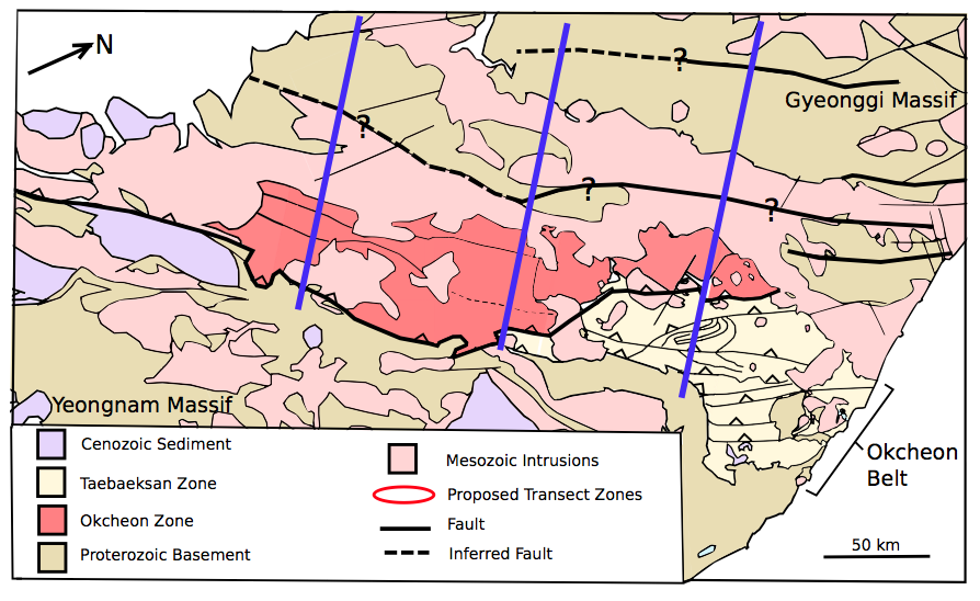
The Okcheon fold-thrust belt formed during the Permo-Triassic collision of the North and South China blocks in Korean Peninsula (Figure 1). The Okcheon fold-thrust belt trends northeast-southwest and spans the central part of South Korea separating two Precambrian massifs, the Gyeonggi massif and the Yeongnam massif. There are two main areas of the Okcheon fold-thrust belt. In the northeast there is the Taebaeksan Zone, which is made up of Paleozoic and Mesozoic sedimentary cover that has been slightly metamorphosed (Kwon et al., 2009). In the southwest there is the Okcheon Zone which brings up older basement rocks. The basal decollement in the Okcheon fold-thrust belt places crystalline basement (red) on top of sedimentary cover (yellow)(Figure 2). Hand samples were collected along the fault exposed between the Okcheon and Taebaeksan Zones to study the localization of shear along this boundary.
3. Sample Preparation
Three samples taken from the two areas indicated above. The samples were cut into thin and thick sections. Thin sections were prepared by Gerry Kloc, using standard procedures. The thick samples were hand cut and then adhered to metal stubs using carbon tape and carbon paint to reduce charging. The samples were sputter coated with a thin layer of gold using one of the Denton sputterers at the University of Rochester’s Institute of Optics. After preparation was complete, all SEM imaging was done using the SEM/FIB Zeiss-Auriga Microscope at the Institute of Optics. Light microscopy was performed in the structural geology lab in the Department of Earth and Environmental Science at the University of Rochester.
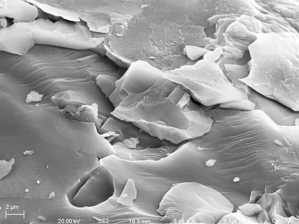
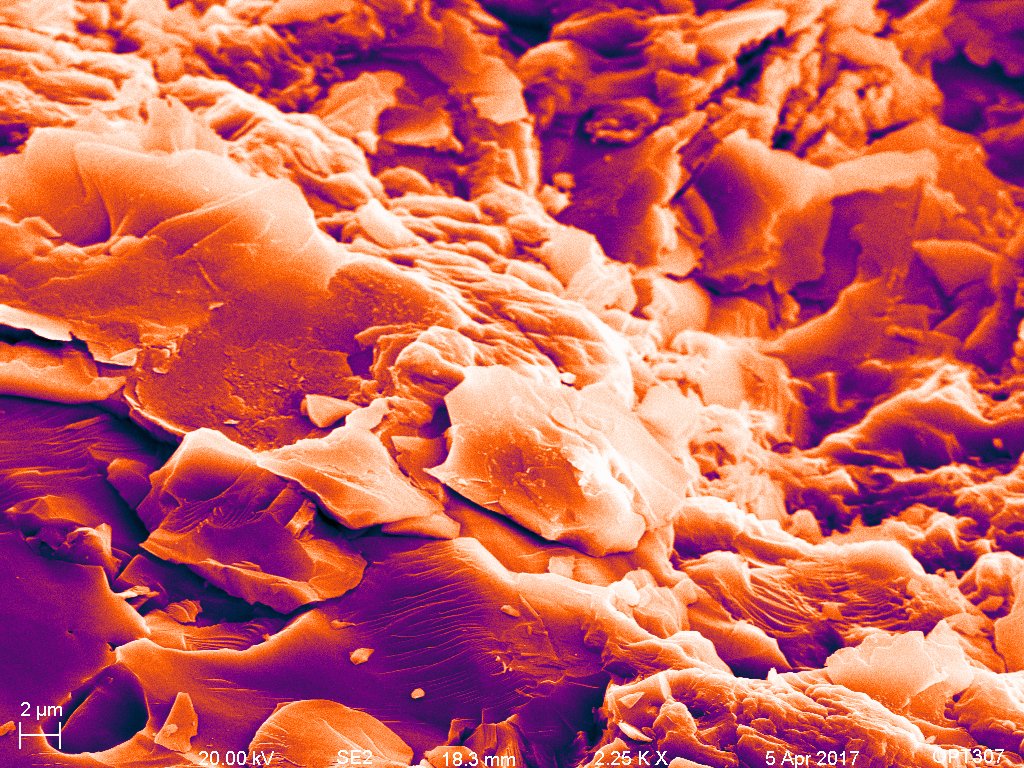
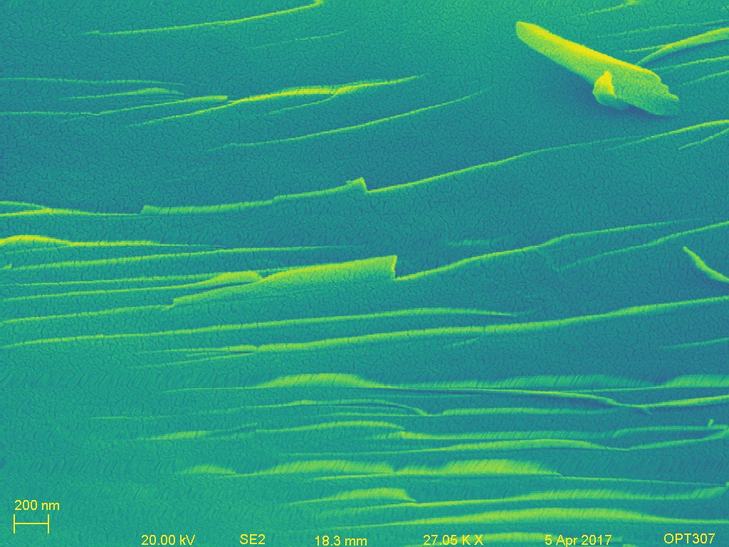
4. Secondary Electron Imaging
5. Backscatter Electron Imaging
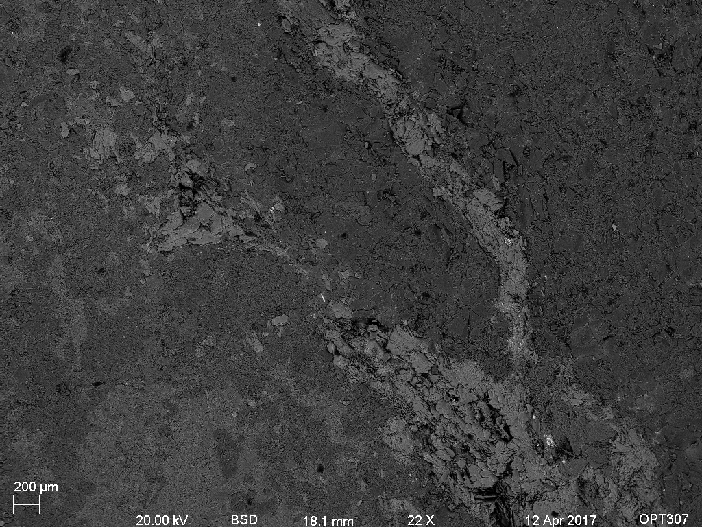
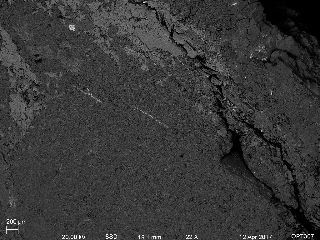
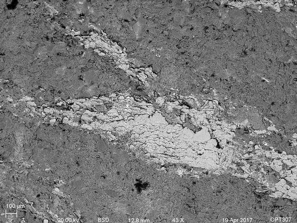
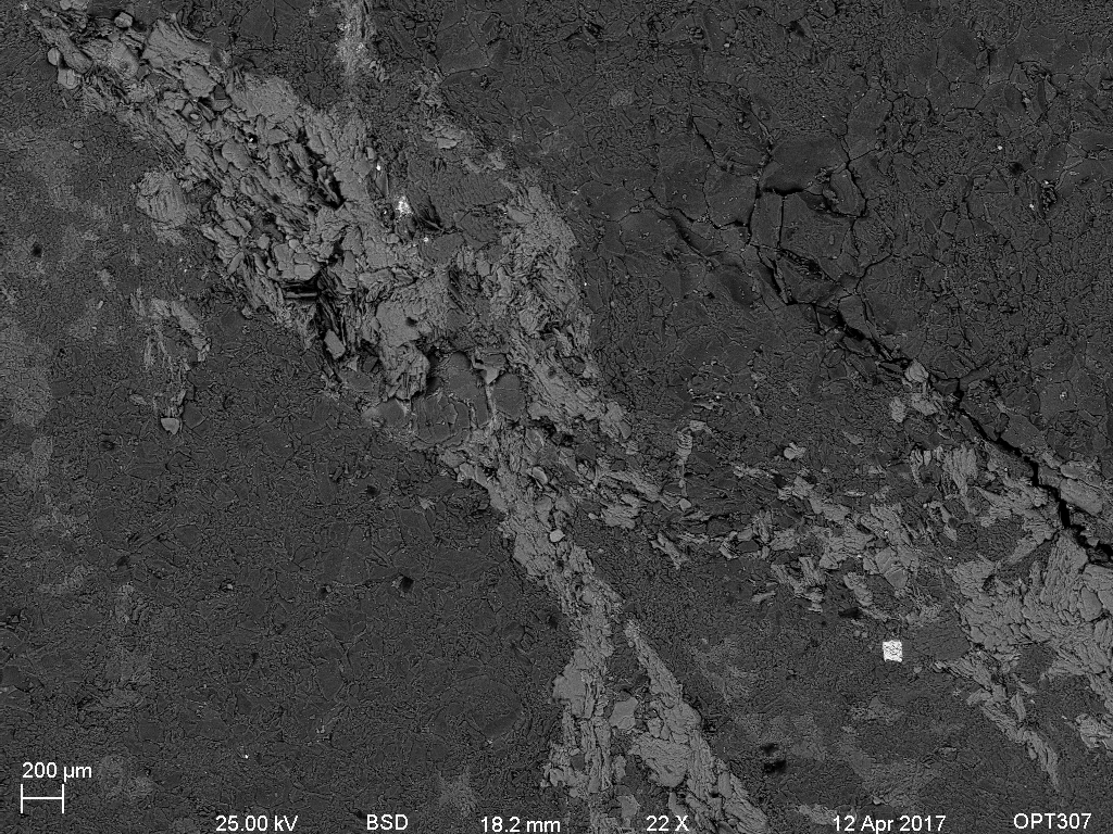
Backscatter electron imaging was the most effective method of imaging the phyllosilicate zones. This is because the micas that are concentrated in these areas are more enriched in heavier elements, such as iron, thus making them appear lighter when using backscatter detection. The white areas are accessory minerals.

6. X-Ray Analysis
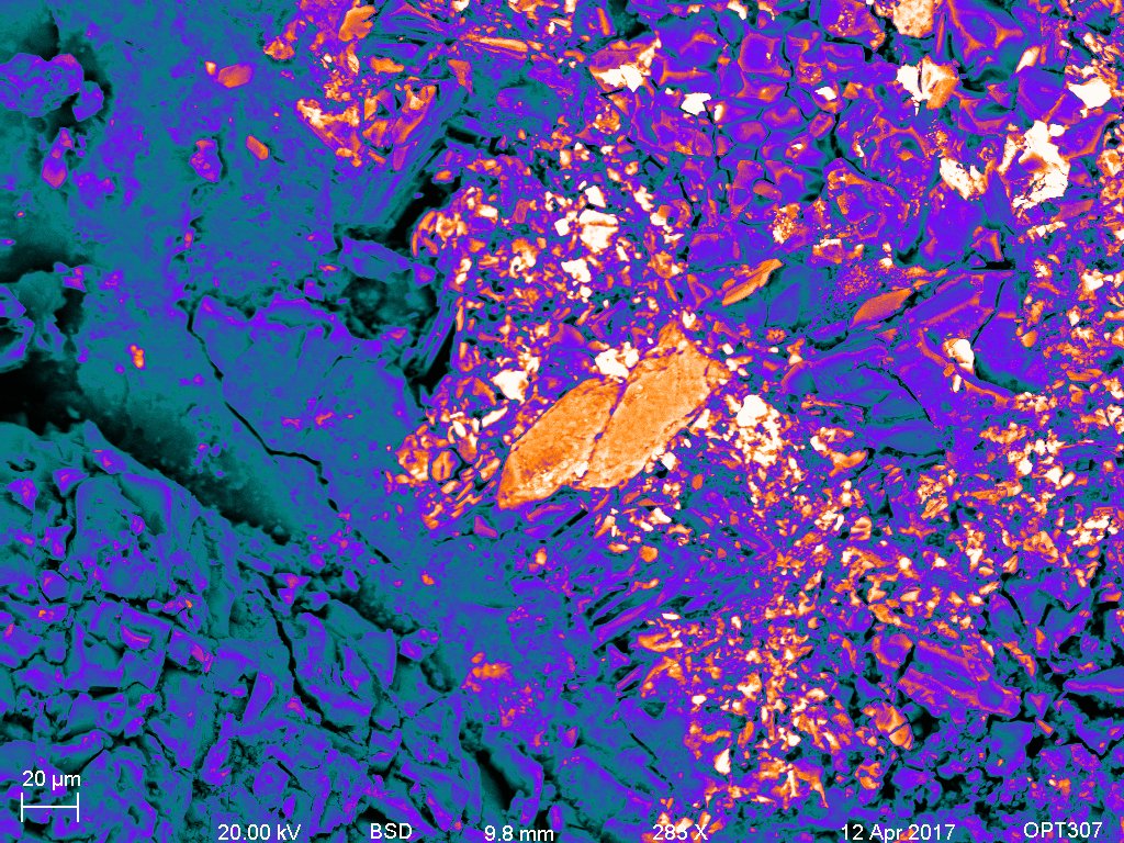
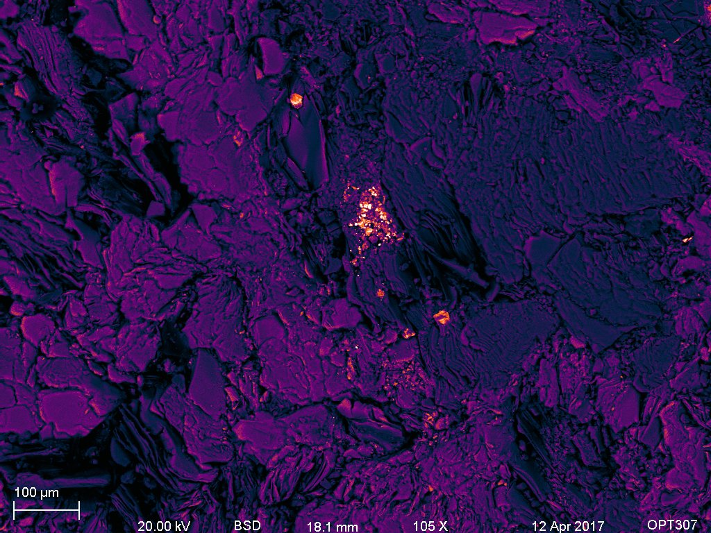
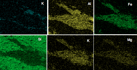
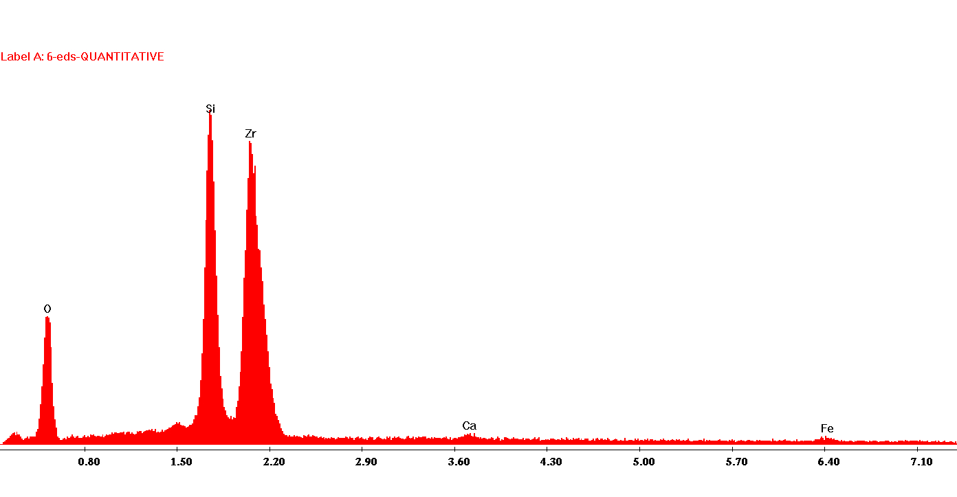
X-ray analysis using EDS was conducted on samples to analyze the composition of the phyllosilicate layers and any possible accessory minerals in them. There were zircons and titanite present towards the contact between the phyllosilicates and the surrounding grains.
7. Conclusions
Using BSD and x-ray analysis, I found that heavier elements, such as Fe, Al, K, Na, and Mg, are concentrated in the phyllosilicate layers during deformation along the fault. Si is less concentrated in the phyllosilicate layers. Accessory minerals, such as zircons, tend to be concentrated along the phyllosilicate layers. This suggests that dating accessory minerals will be possible and should accurately give the age of deformation along the fault.
Acknowledgments
Thank you to Brian McIntyre and Caleb Whittier for helping me not break the SEM and for providing invaluable guidance.
References