Morphologies of Experimentally Shocked Zircons
Martha L. Miller
University of Rochester, Department of
Earth and Environmental Sciences
1. Introduction
As part of a larger study looking to identify and quantify the effects shock metamorphism has on the diffusion of radiogenic geochronometers, researchers travelled to Johnson Space Center to utilize the Flat Plate Accelerator (FPA) to simulate a meteorite impact to the samples. This portion of the study is meant to characterize the morphology of the zircons after the experimental shock.
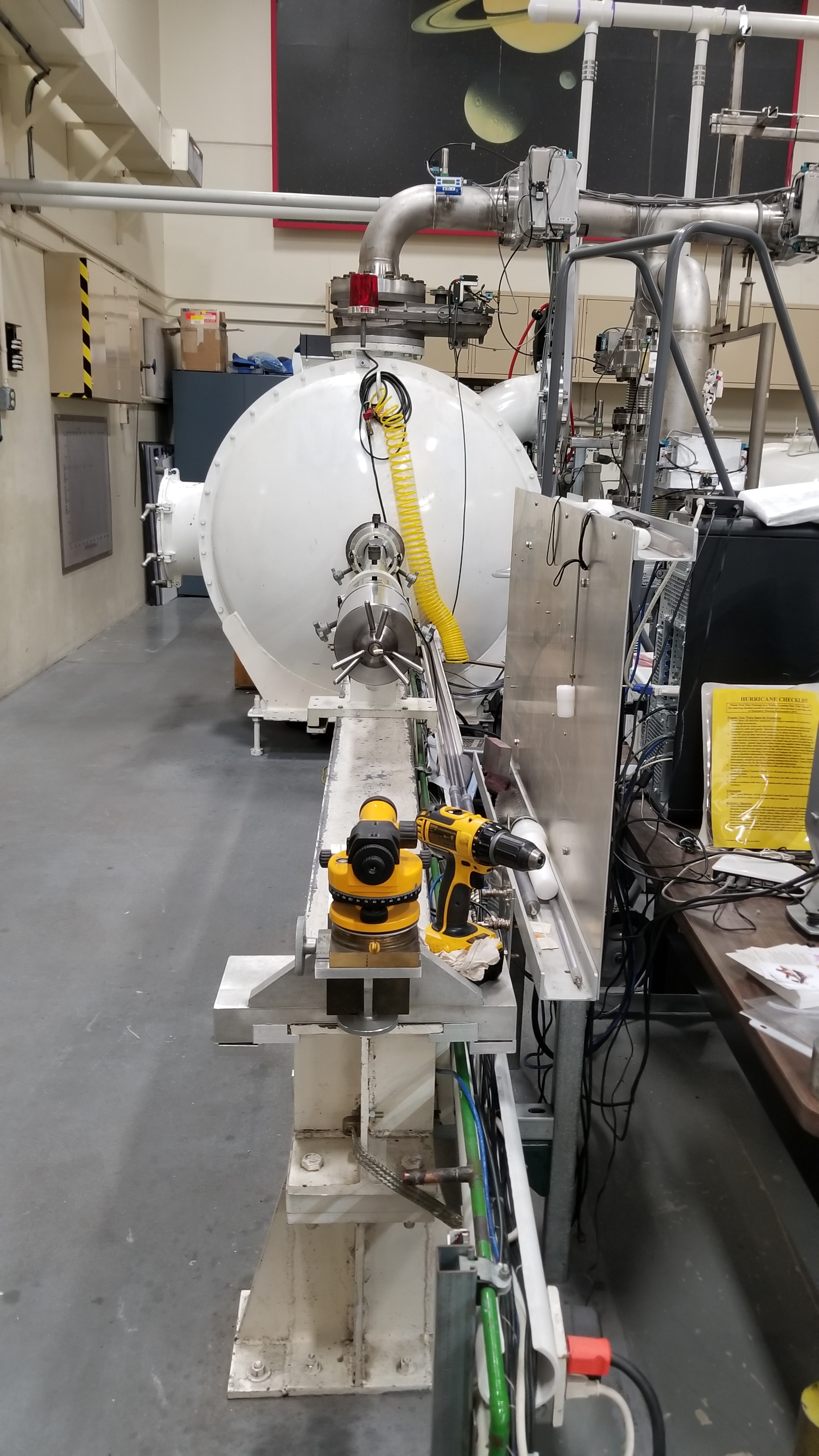
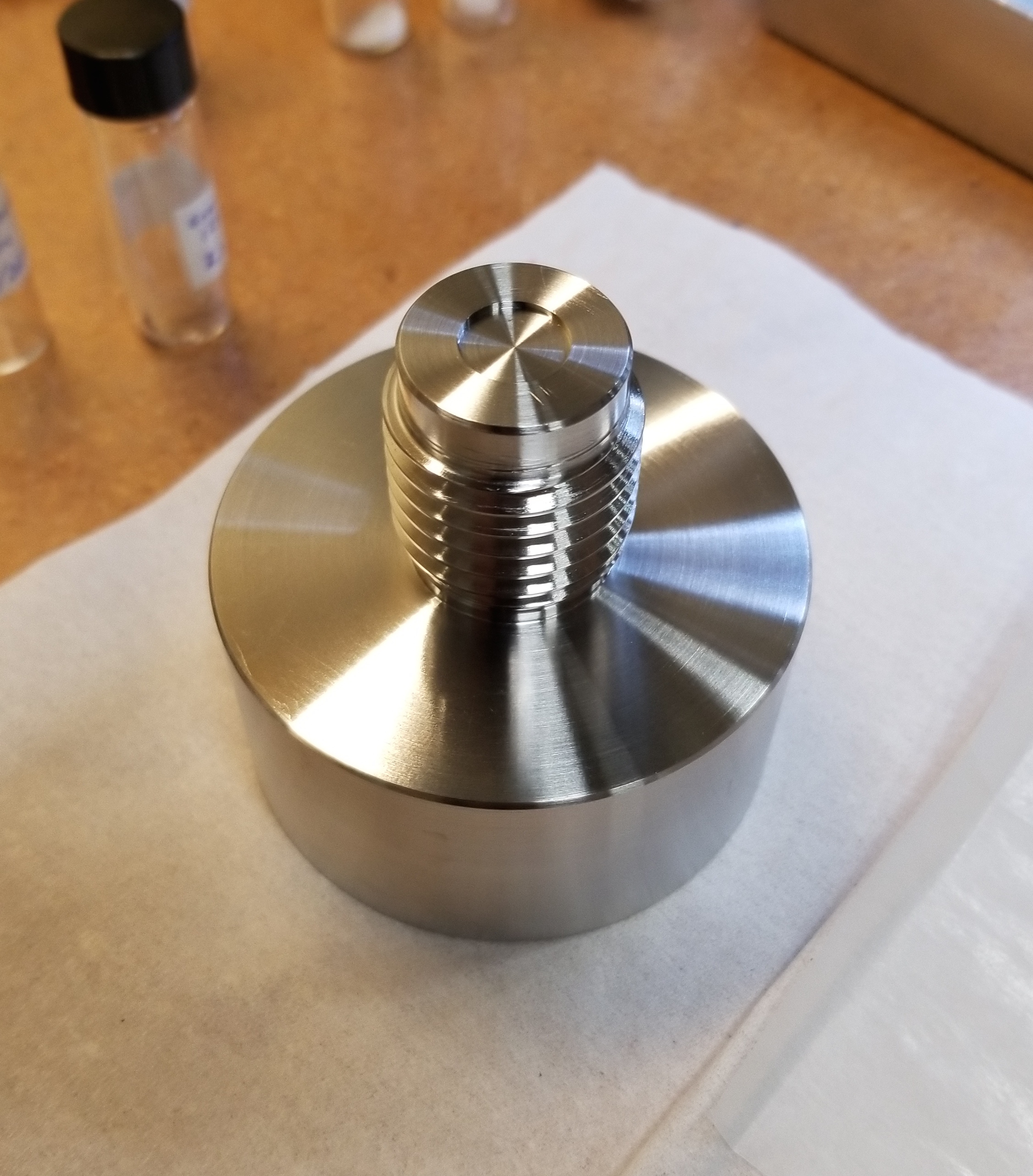
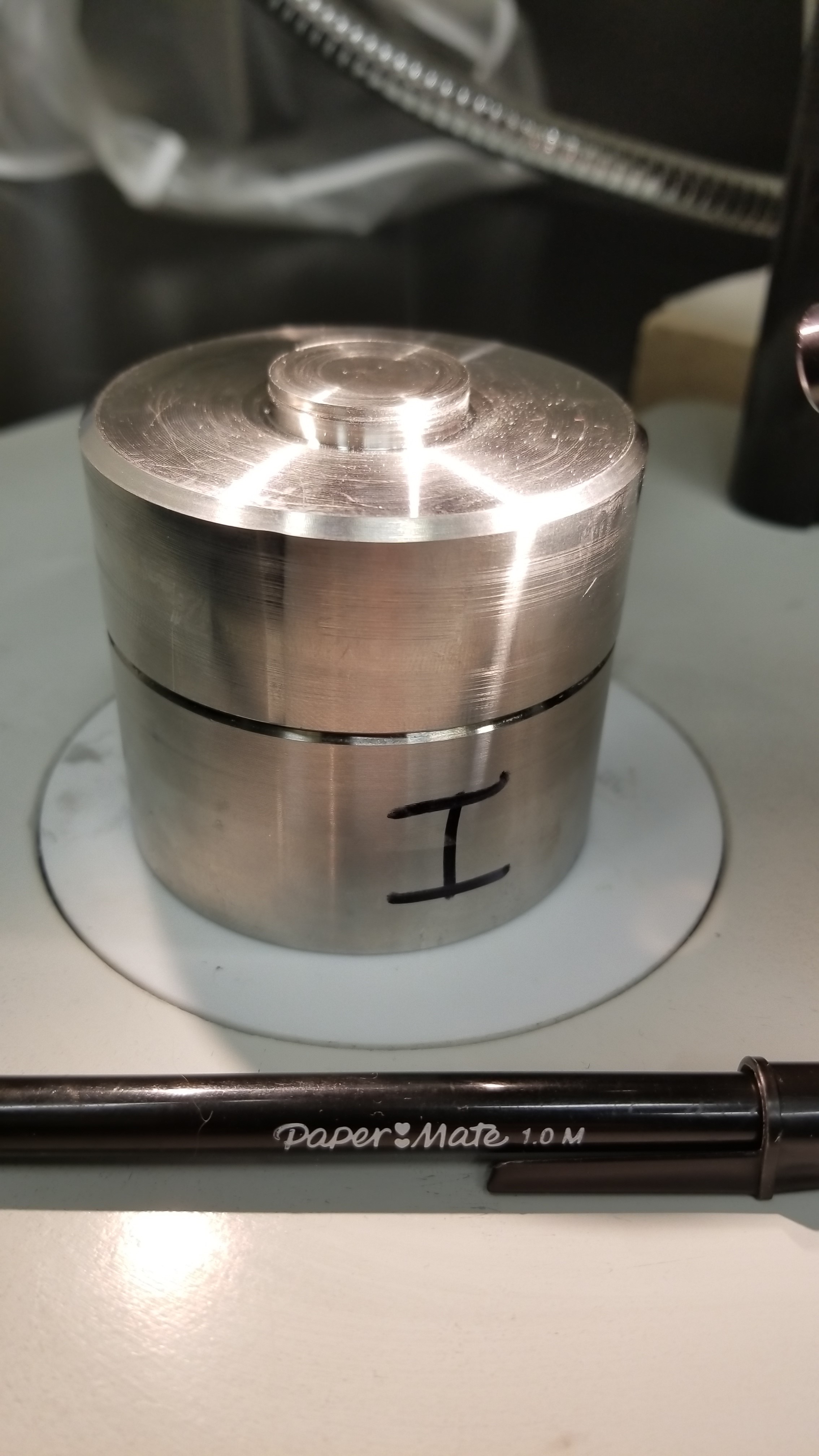
Figure 1: The FPA loaded with sample 2 (left). The target, uncapped and without the sample. (center). The target containing sample two after the experiment and the machining required for sample extraction (right).
Two samples were were prepared for our experiment. The first sample was entirely Keuhl Lake zircons, while the second sample was a mixture of a well characterized Bishop Tuff sanidine and Keuhl Lake zircons. The second sample was ~95% sanidine (115 mg) and ~5% zircon (5 mg). Ian Szumila prepared the zircons, used in both samples, by cutting large zircon grains in half and crushing one half of each grain. The remaining halves were saved for future work. Szumila also crushed the sanidine used in sample 2. Each crushed mineral was sieved through a series of mesh sizes and the fractions separated. All grains used in this experiment were from the 150 - 250 micron fractions.
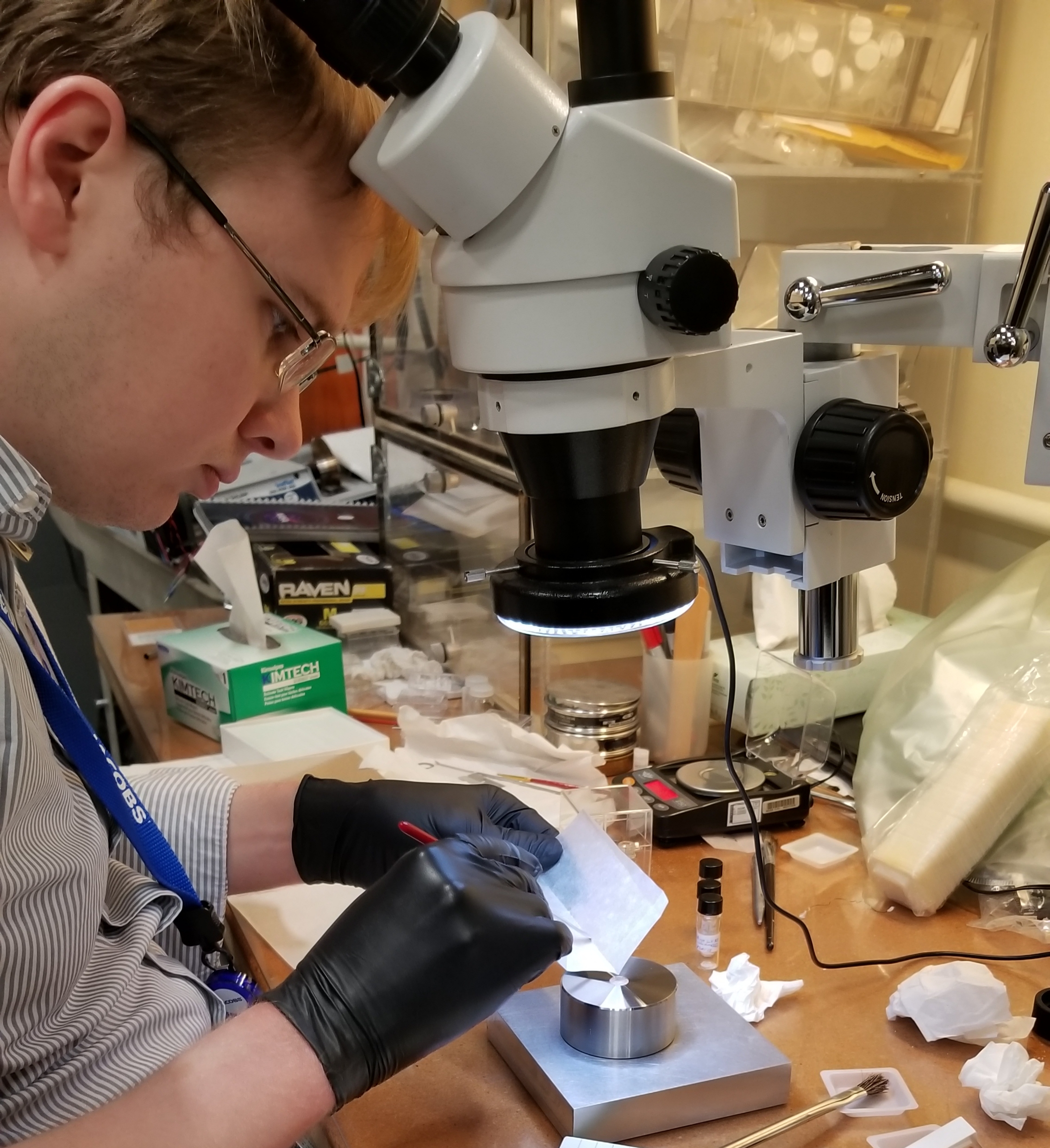
Figure 2: Ian Szmulia preparing the sample for loading into the target.
Sample 1 was shocked with 28.4 GPa, whereas sample 2 was shocked with 23.8 GPa. The reduction in pressure, between sample 1 and sample 2, was because the flyer plate of the target housing for sample 1 was blown off during the "shot". This resulted in an almost complete loss of sample 1; however, as you will see below, information was still gained from this sample. Between shots the interior of the FPA is vacuumed out. This meant that the debris from sample 1 could be collected for analysis. Through use of a Light Microscope (LM) and a Scanning Electron Microscope (SEM) it was determined that the debris from sample 1 was composed primarily of melted Teflon (from the projectile used for the impact), metal from the target, and an ash-like substance that had trace amounts of zirconium.
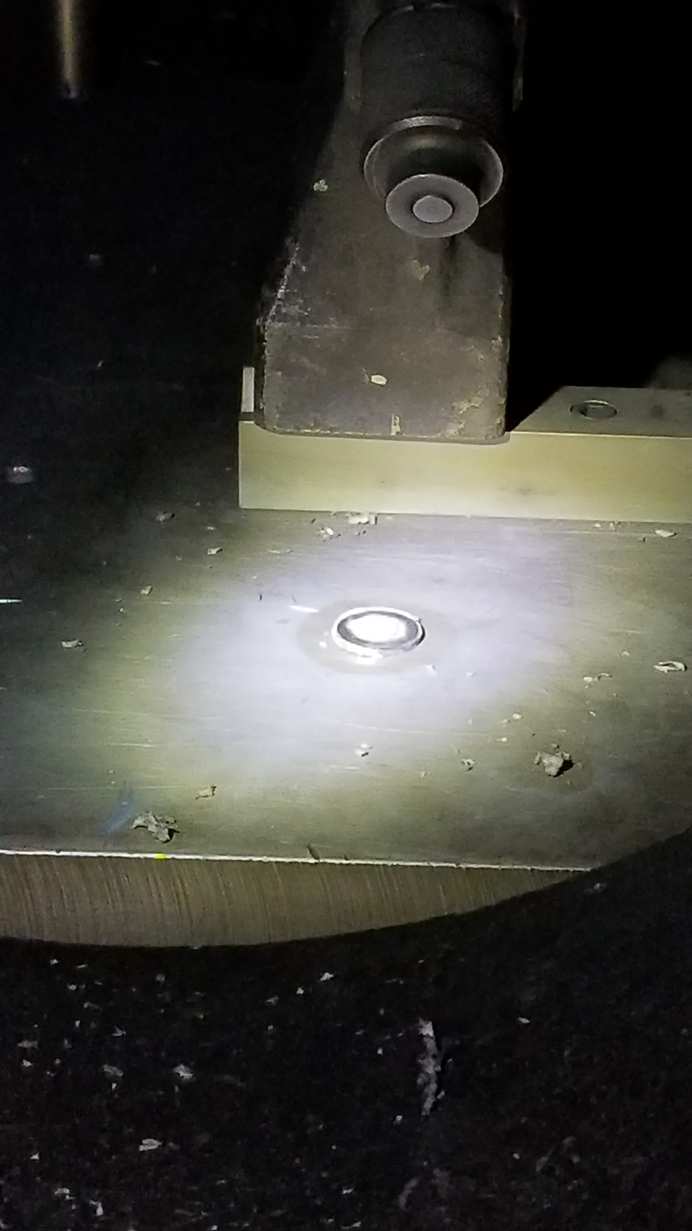
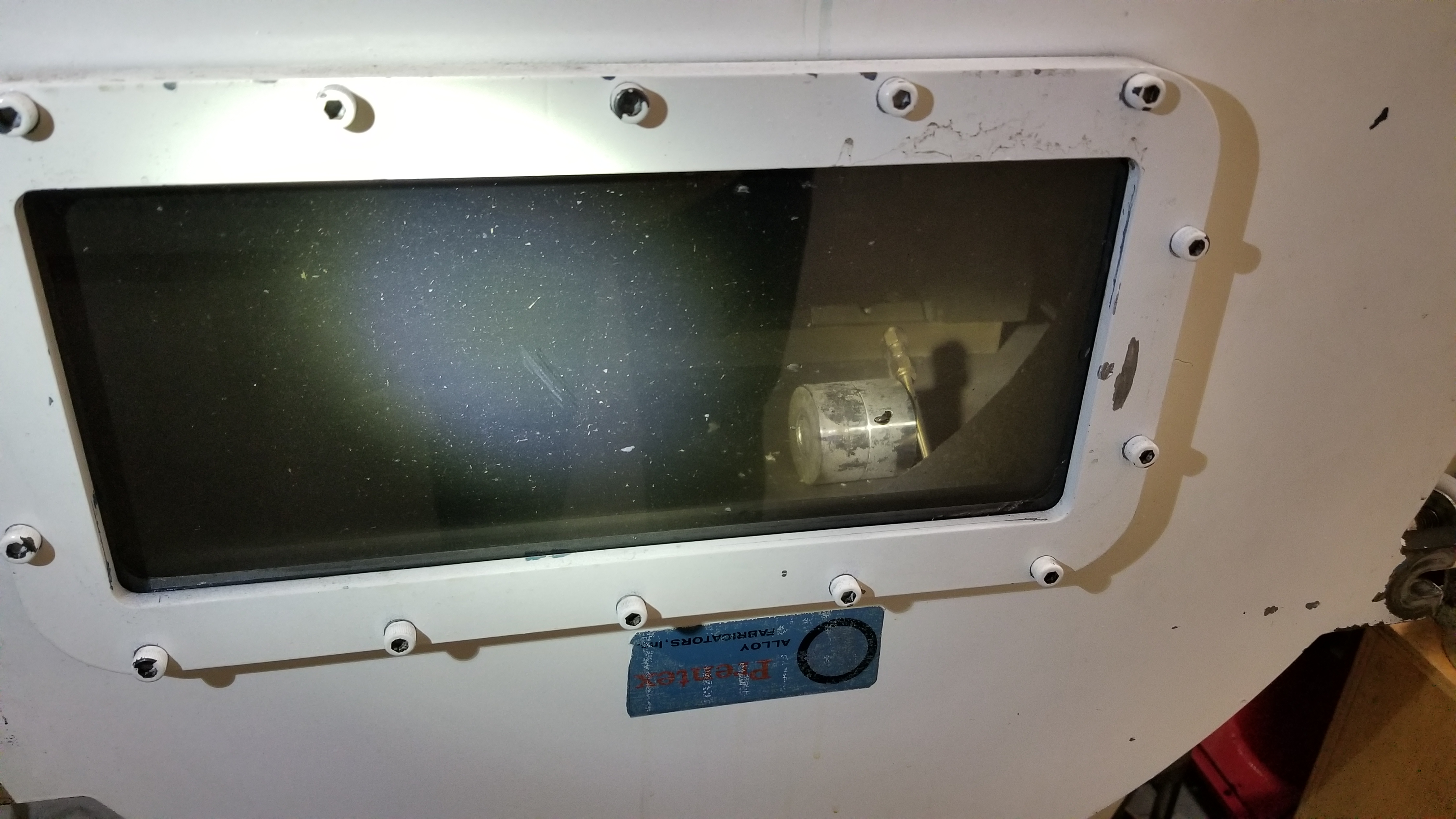
Figure 3: The flyer plate is in the light, whereas the target is still mounted above, and the sample area is exposed (left).
Target 2 after the experiment, while still inside the FPA. Notice that sample 2 is not exposed (right).Various microscopy techniques were used to study these samples: LM, SEM secondary electron imaging (SE), SEM backscatter electron (BSE) imaging, and energy dispersive x-ray spectroscopy (EDS) on the SEM. Additionally interaction modeling (or electron flight simulation) was used to better understand the interaction volume of Zr for these assorted SEM techniques.
2. Sample Preparation
Sample preparation for LM was was minimal. Sample 1 was simply transferred into a series of petri dishes. This allowed for the debris material, with use of the LM, to be sorted by approximate composition (materials mentioned above). Sample 2 preparation required removing the sample from the target in a manner that would limit the amount of metal from the target, as well as have minimal effects on the exterior geometry of the sample.
To prepare the samples for SEM techniques each stub mount was lined with double sided carbon tape and the samples were sputtered coated with carbon.
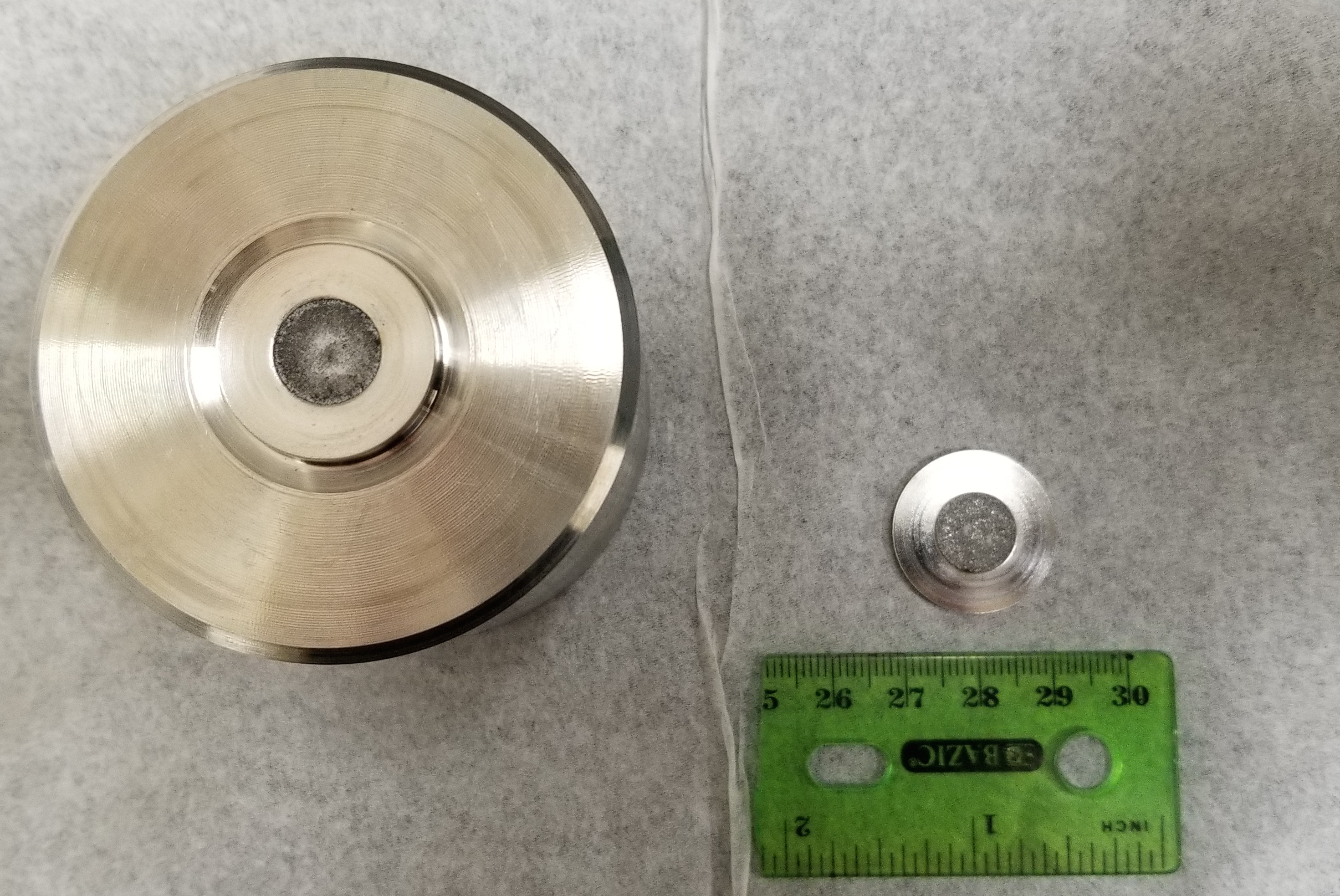
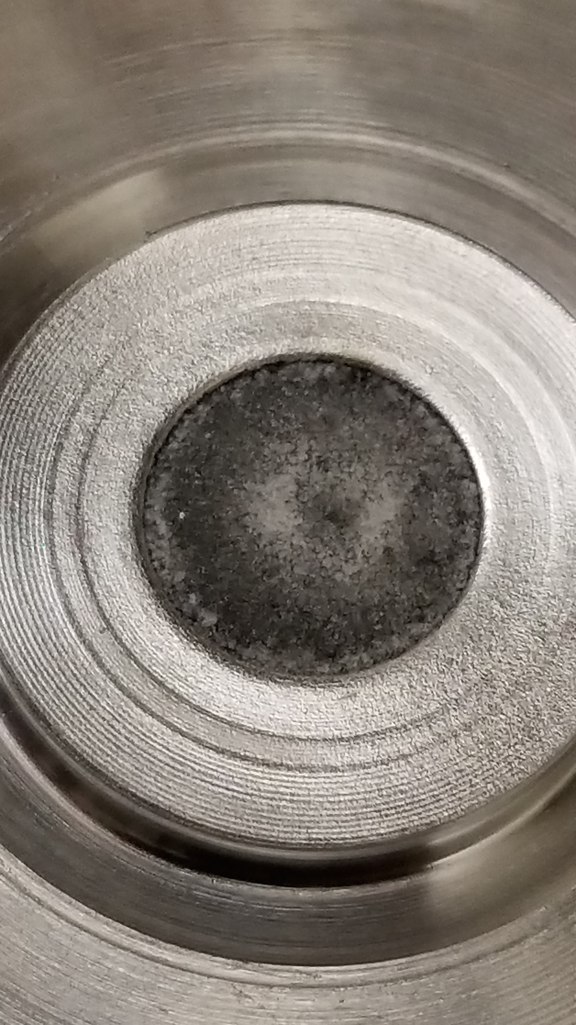
Figure 3: Sample 2 in the open target (left), also sample 2(right).
3. Interaction Modeling
Since locating and imaging the shocked zircons was he principle goal of this portion of the study it was important to understand the interaction volume of zirconium for these samples. A modeling program was used to simulate electron flight using the ________ software owned by the Institute of Optics at the University of Rochester. Interaction volume was modeled with 2000 trajectories, a tilt of zero degree, and an acceleration voltage of 20 KeV. The result of the modeling was especially informative for seeing the interaction volume for X-rays generated under these conditions, making collecting an X-ray map more efficient.
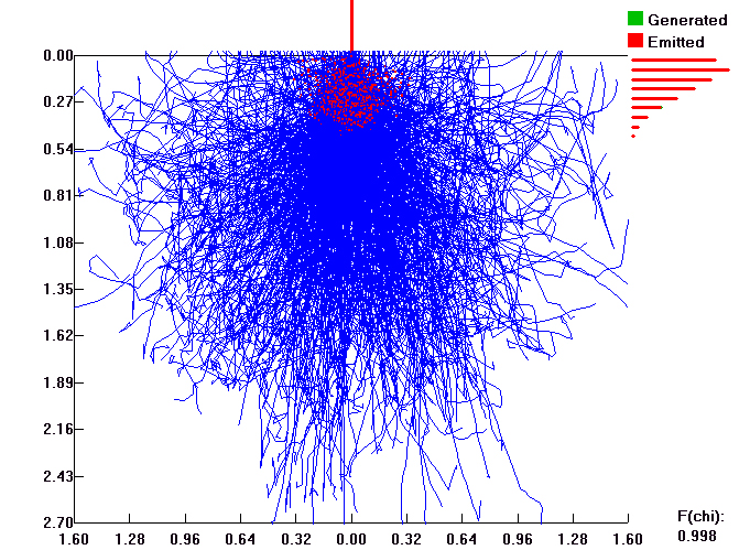
Figure 4: Model of Zr interaction volume.
4. Light Microscopy
Light microscopy was the first microscopy technique used to look at the samples. Images were collected to show surface features of formed from the shock to sample 2. Additionally images were collected of sample 1, as aforementioned LM was utilized as a means to begin the preliminary sorting of the collected material. Imaging was done in the Trail Lab at the University of Rochester. The ability to capture images in color with LM, is an asset of the technique, this is particularly useful for seeing where metal from the target may have incorporated into to the samples.
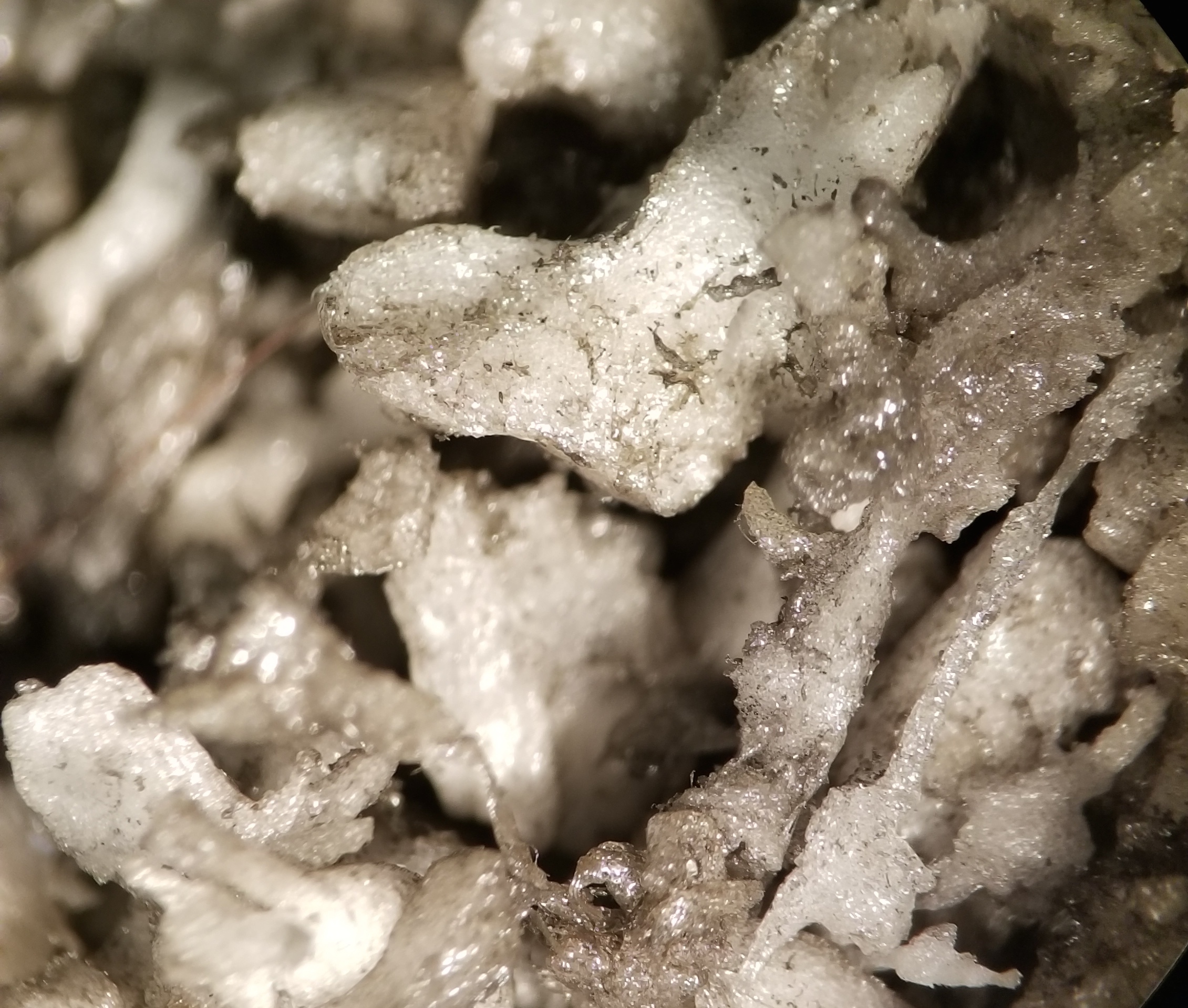
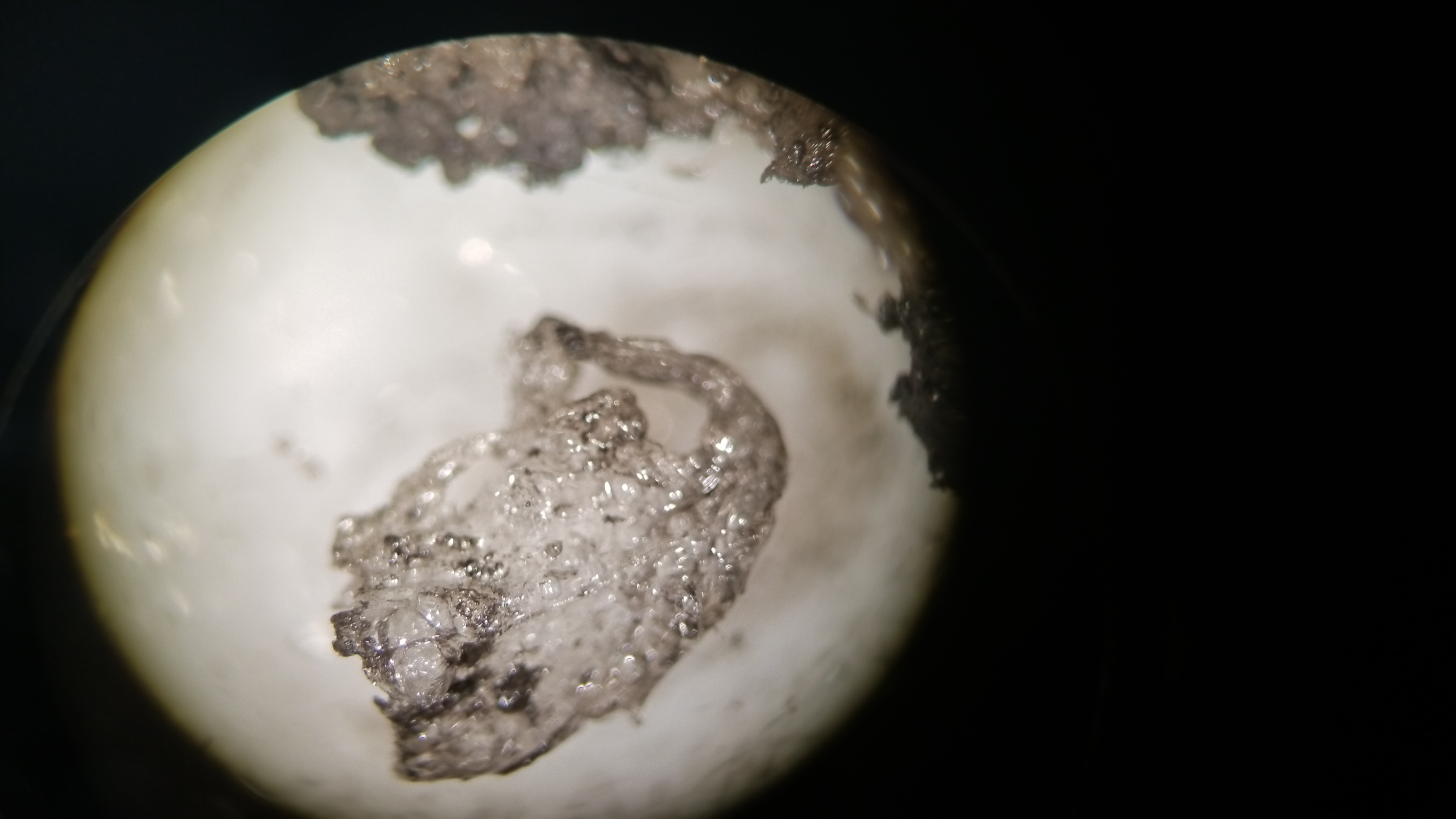

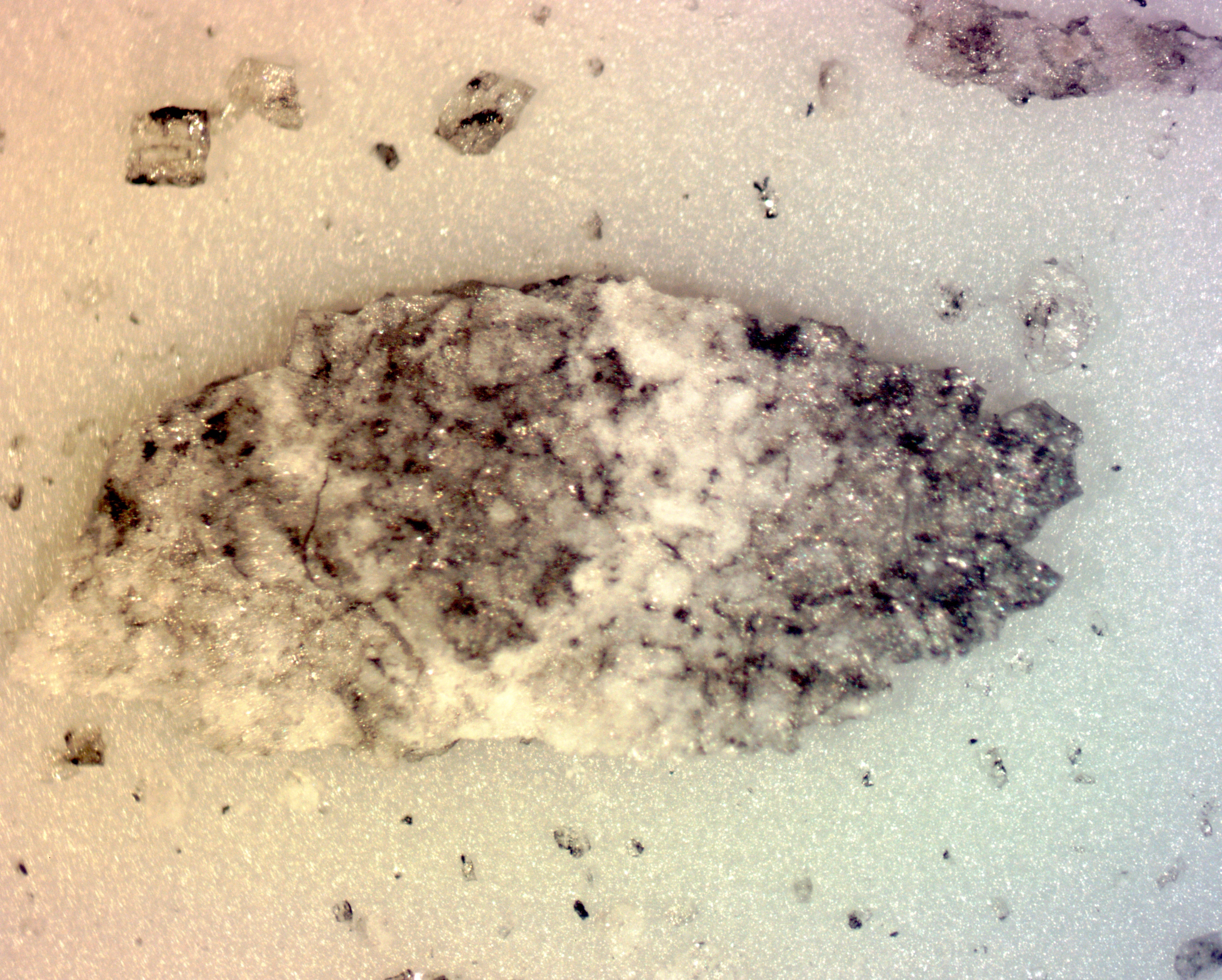
Figure 5: Debris from sample 1, predominantly melted Teflon (top left) melted Teflon from sample 1, note the fibrous morphology (top right), sample 2 in entirety (bottom left), large grain from sample 2 (bottom right).
While the differences in sample 1 and sample 2 are clear in the LM images, this technique does not allow for the clear identification of the zircons.
5. Scanning Electron Microscopy
As mentioned above, three SEM techniques were used: SE, BSE, and EDS. SE detection is useful for analyzing the surface morphology of sample 1 and 2, as well as unshocked Bishop Tuff sanidine and a half of one of the Keuhl Lake zircons that was reserved for later analysis. Having both shocked and unshocked material is critical for understanding the changes to crystal structure. BSE is utilized to compare relative atomic mass of the components of a sample. The brighter an area on the image the higher the atomic number of the chemical component in that area. This variance in brightness is because elements with high atomic numbers more strongly backscatter electrons than elements with low(er)atomic numbers. BSE was especially useful for this study because the atomic mass of zirconium is much greater than the chemical components found in sanidine, making zircons reasonably conspicuous. An interesting result of utilizing this technique was finding the large areas of inclusions in the Keuhl Lake zircon. EDS was also implemented to confirm where the zircons had recrystalized. This technique was helpful in distinguishing areas where needlelike zircons and metal from the target had formed in the same region of a crystal. The metal from the target was identified by a combination of Fe and Cr components. EDS was also instrumental in identifying the various components of the inclusions in the Keuhl Lake zircons.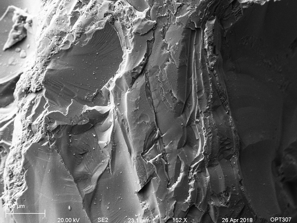
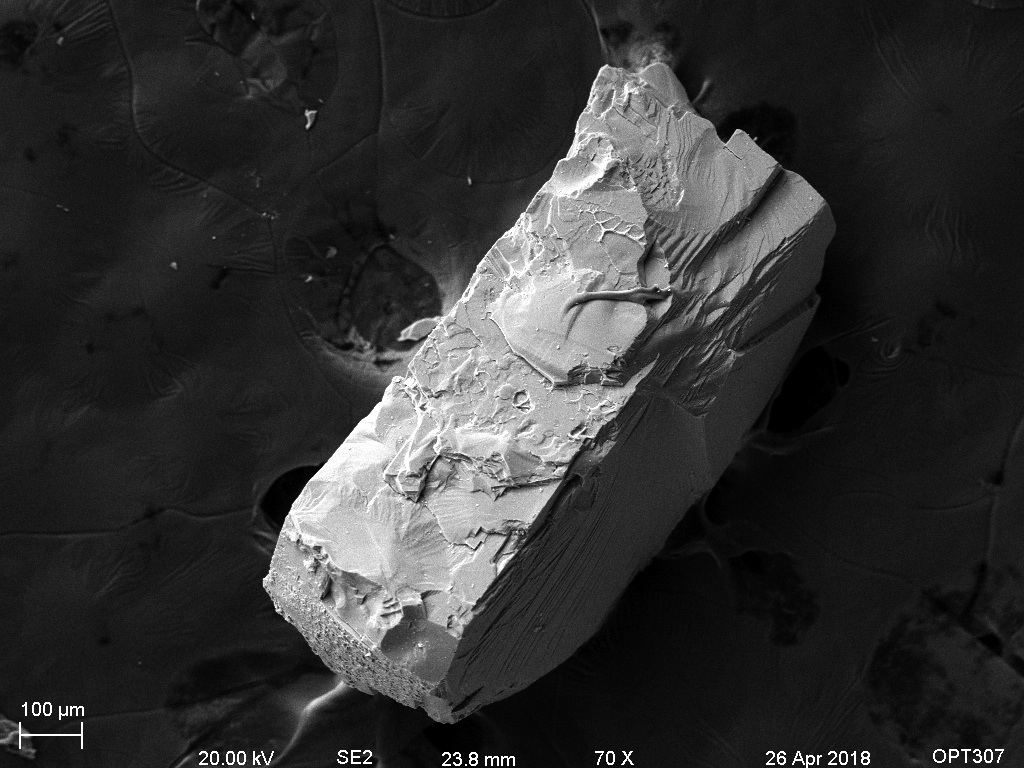
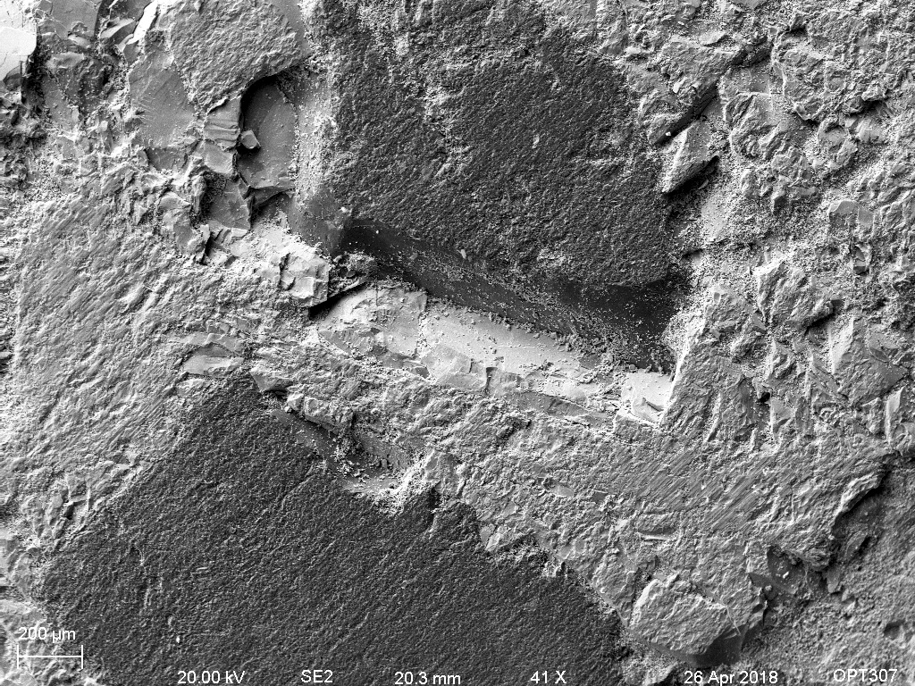
Figure 6: Starting material in SE. Bishop Tuff sanidine surface of a single grain (top left) Bishop Tuff sanidine, single grain (top right), Keuhl Lake zircon (bottom).
The SE image of the zircon makes it evident that there are some inclusions in the grain, but offers little evident to what they may be, because of this BSE and EDS was performed and an elemental map was created. From this map we see that the elemental compositions of the inclusions are potentially a plagioclase feldspar and a potassium feldspar.
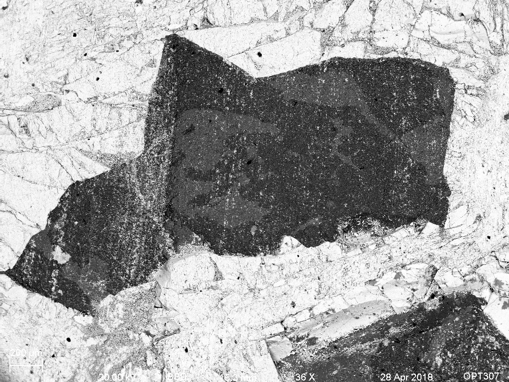
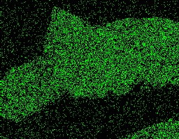
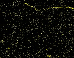
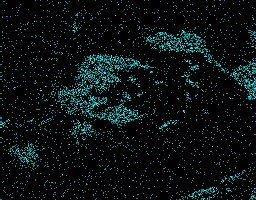
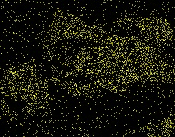
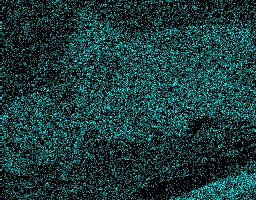
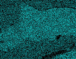
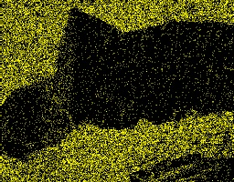
Figure 7: A backscatter image of one inclusion in the unshocked zircon (top row). Elemental maps of the same view. Elements are as follows Al, Ca, K (middle row) Na, O, Si and Zr (bottom row).
The backscatter image is of a portion of sample 1 that appeared "ash-like". The image shows some bright point, based on the later elemental maps it appears these could be from zircon and/or from metal originating in the target.
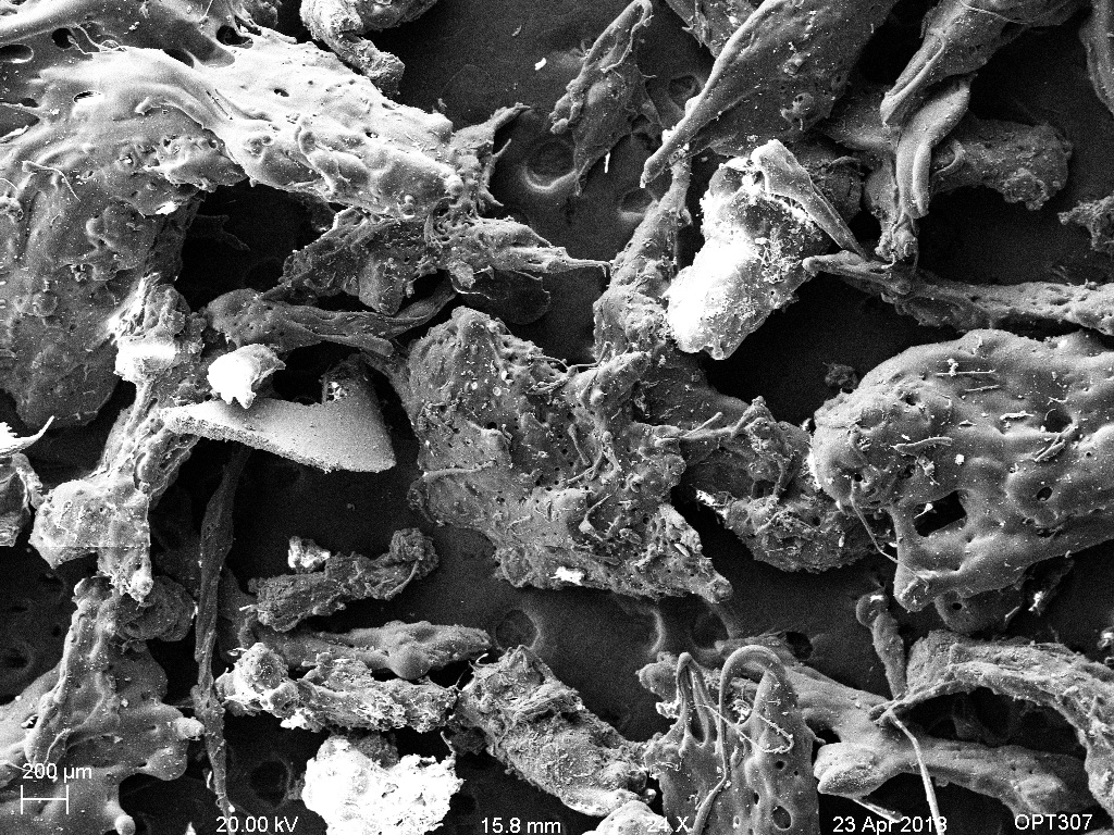
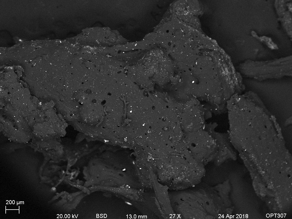
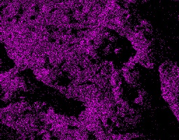


Figure 8: A secondary electron image of the melted Teflon from sample 1 (top row). A BSE image of a single piece of Teflon (bottom right) The next three images are elemental maps of the same view, elements are as follows C, Cr, and Zr.
Notice that bright areas on the right image are where the zircon are located. While some difference in brightness and texture may make these areas noticeable in the SE image, the difference of minerals within the grain is obvious in the BSE image.
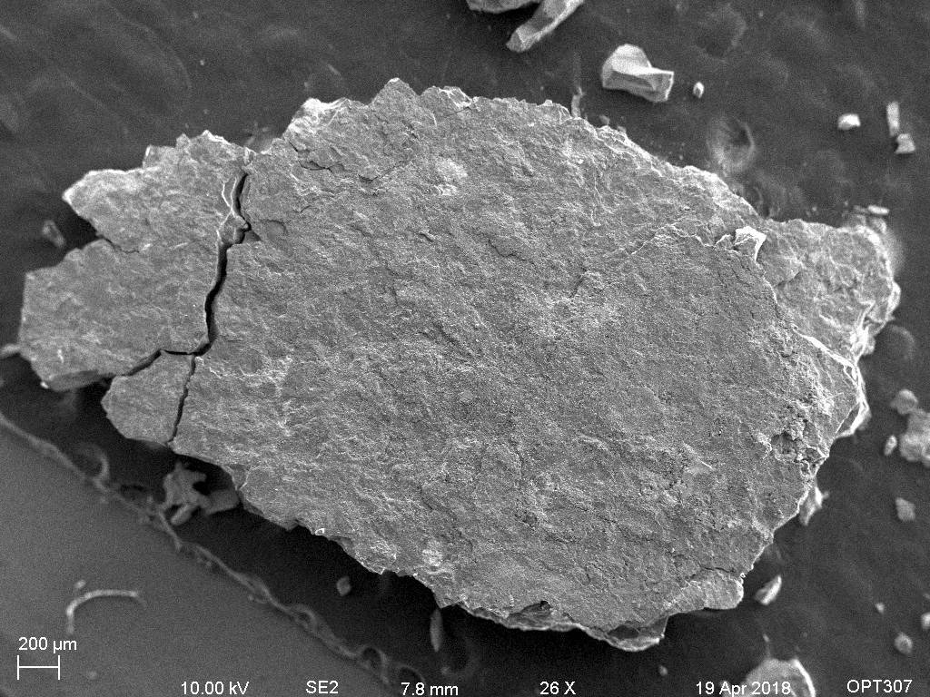
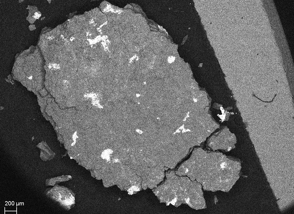
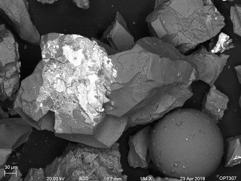
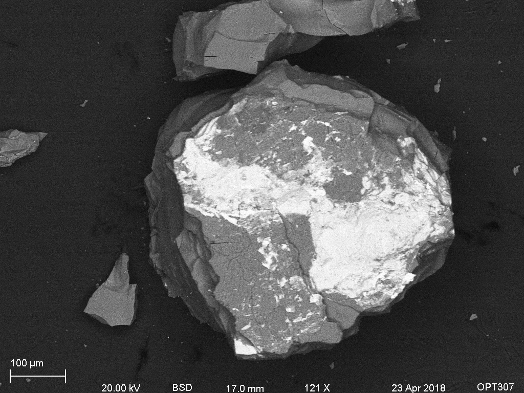
Figure 9: An SE image of a large grain from sample 2 (left), a BSE image of the same grain, with a different orientation (right).
The upcoming images are to illustrate the surface of the large grain seen above. Comparing the sanidine to the original grain, shock fractures are evident. Likewise, the aggregate of zircon grains, most less than a micron in size, are very different than the starting material.
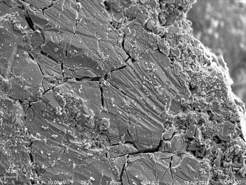
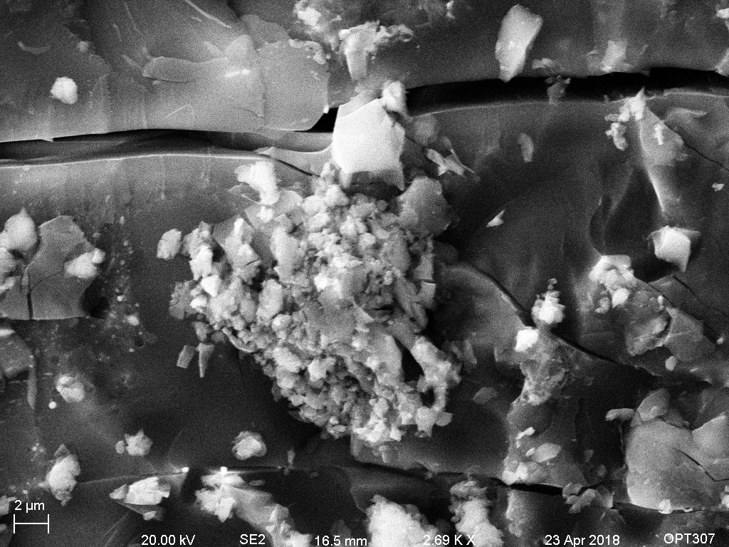
Figure 10: An SE image of the surface of the large grain from sample 2 (left), an SE image of zircon aggregates(right).
The following backscatter image, and the corresponding elemental maps are included to show how, the metal from the target can appear bright in BSE as the zircons do. Incorporating multiple microscopy techniques avoid assumption and/or misinterpretation of the data.
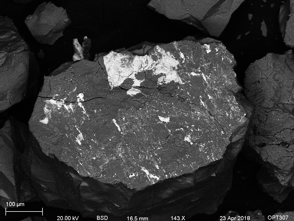

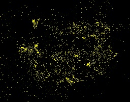

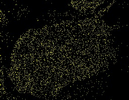
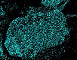
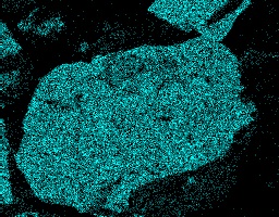
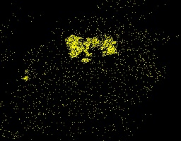
Figure 11:A BSE image of a grain from sample 2 (top right). The next seven images are elemental maps of the same view, elements are as follows Al, Fe, K (top row) Na, O, Si and Zr (bottom row) .
6. Conclusions
Studying the morphology of zircons that have experienced shock metamorphism with various microscopic techniques showed that crystals morphology clearly changed. Frequently the zircons aggregated as of grains less than a micron in size. Less often they appear as elongated needlelike crystals sparsely scattered through the sanidine; this latter structure appears to happen where metal from the target has been incorporated into the sample. Such changes in morphology are extremely likely to effect diffusion of radiogenic geochonometers, future work with LA-ICP-MS, and SIMS will be done to determine the extent of these effects.
Acknowledgments
Thank you to Ian Szumila for preparing the samples, and working out the logistics for our experiment, to Justin Simon for supplying material for analysis and to Dustin Trail for supplying material for analysis and for his continued support and advisement!
I would also like to thank Brian McIntyre for his gift of helping. He has been a great support for this project and I hope to work with him in the future.
In addition, I extend great gratitude to my children for encouraging me to pursue my dreams.