Diamond Tool Wear - Observation by Scanning Electron Microscopy (SEM)
Shai N. Shafrir ?? ?????
Abstract
In Deterministic Microgrinding (DMG), the wear of diamond grains is a significant problem and the cause for lowering grinding efficiency, which leads to pull-out (loose) of diamond grains from the binder and the appearance of scratching. It contributes to poor surface finish, increased machining forces, and increased tooling costs. At the Center for Optics Manufacturing (COM), we have been primarily interested in resin and bronze bonds diamond tools with a diamond size of ~2-4 microns. Unfortunately it is difficult to directly measure fine abrasives mechanical response. A qualitative model was introduced using Scanning Electron Microscopy (SEM) to better analyze diamond wear for different bond matrixes. Observation of the tool face after a variety of grinding and dressing operations provided characteristically different surfaces for each case.
|
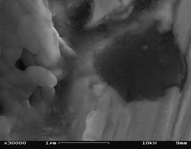
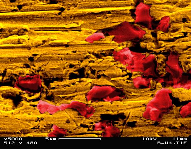
Fig 1. Bronze tool after 8 working cycles (BSE detector) |
|
|
|
Introduction
Tools are constructed of a wearable matrix embedded with diamond particles and can vary in diamond size, abrasive concentration, and bond material. Ultimately the matrix ability to wear can have a large impact on the tool ability to grind the material, resulting in tool failure when it is not wearing properly. Excelerated tool wear will result in a dull tool surface, and will subsecwently loss it's ability to remove work material. A better understanding of tool wear mechanism is needed in order to find an optimum condition between these two extremes, by maintaining proper grinding conditions to eliminate tool failure.
The tool wear process is often broken into three
modes of removal: 1) Diamond blunting, 2) Diamond pullout, and 3)
Bond wear [1].
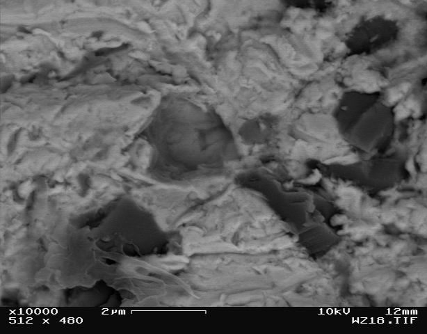
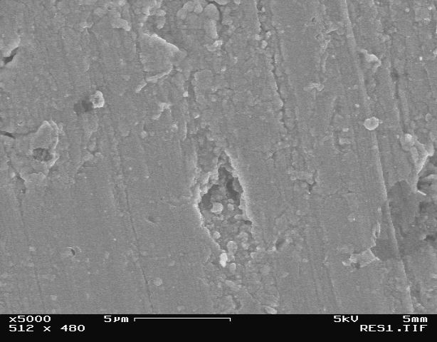
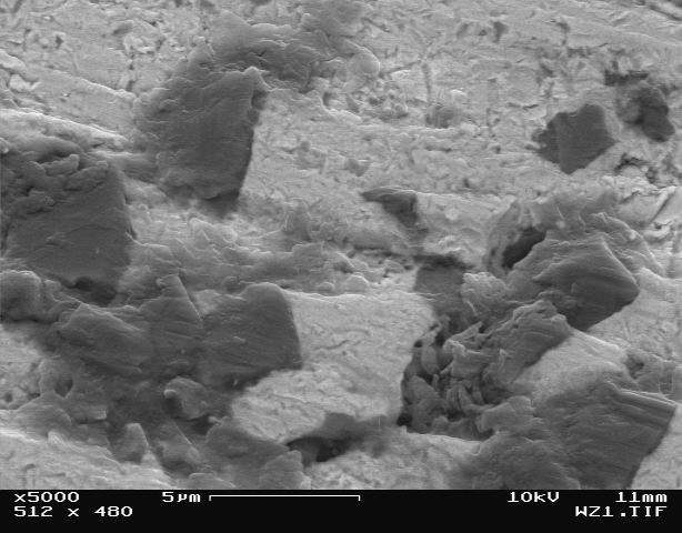
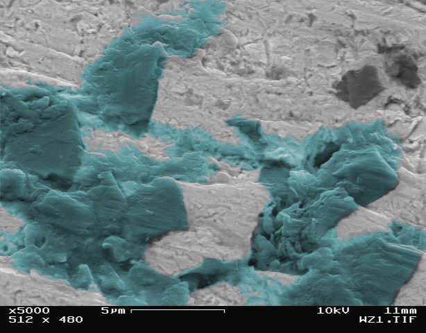
Fig 2. Bronze tool after 6 cycles, notice the hole
in the middle due to diamond pullout.
Image using the BSE detector, gold coating on surface.
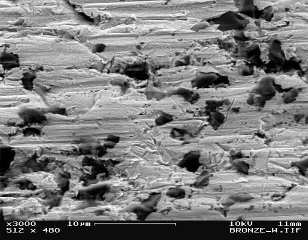
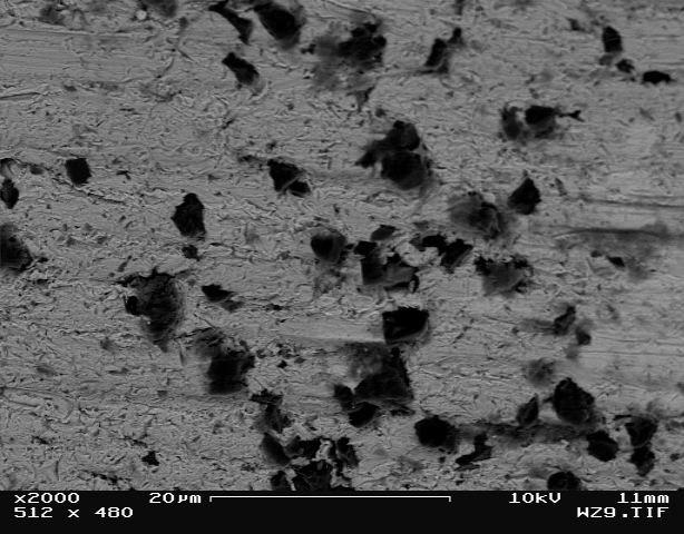
Diamond blunting can occur during the grinding process and results in higher diamond forces due to the increasing contact area since both tangential and normal force components increase linearly with wear flat area [2]. These increased forces may lead to diamond pullout once they exceed the bond strength [3]. It should also be noted that tool wear is measured by the total volume to tool removed, and that bond wear clearly has the greatest impact on this value since diamond blunting and diamond pullout provide minimal volumetric change[4].
Bond materials include bronze and resin, are typically softer than the abrasives and therefore amy by susceptible to wear by erosion as swarf (glass chips) impact the diamond over time.
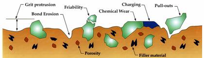
Fig 3. Schematics of the tool bond matrix [5]
The bond purpose is to hold diamonds and wear in a controlled
way. There are three types of bonds for optics manufacturing [6]:
Metal Bronze bonds are in widespread used in optical shops.
They do well on optical materials, especially when used with light
grinding pressures. Bronze bonded diamond tools are the preferred
choice when hard an brittle materials must be ground with a
minimum of edge chipping [7]
Vitrified Glass matrix, often porous hard, but may be
relatively friable (excessive backing under pressure). Pores may
aid coolant penetration, and the storage of swarf (removed glass
particles).
Resin Polymer matrix, relatively soft, less wear
resistance and temperature resistance. Smoother grind, since bond
deform s under loading on of diamonds.

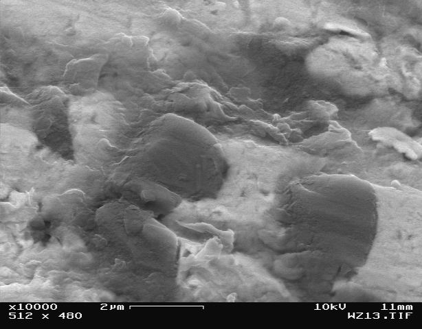
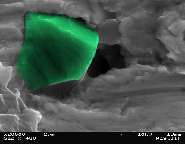
Fig 4. Bronze bond, notice the diamonds in the
bond material.
Image using the BSE detector, gold coating on surface.
Experimental Procedure
We suggest to investigate a comparison between two
different diamond ring tools, used mainly on a Contour
Deterministic Micro-Grind (CDMG) precision optics Moore
Nanotech® 150AG [8] Computer Numerically Controlled (CNC)
platform.

Fig 5. Moore Nanotech® 150AG at work with a resin tool.
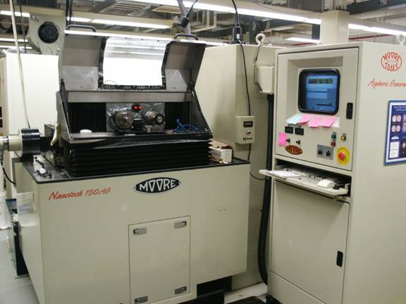
Fig 6. Moore Nanotech® 150AG platform.
Observation of the tools face will take place after a variety of grinding and dressing operation on BK7 Crown glass. The tools of interest: resin and bronze bonded tools (fine tools, diamond size ~2-4 microns).
Microscopic Techniques
1. Secondary Electron Imaging (SEI): mix of two secondary electrons detectors are being used for the resin tool; in-lens and the in-chamber detectors.
In-lens SE detector is good for high-resolution topographic imaging. In general the topographical image is dependent on how many of the secondary electrons actually reach the detector.
In-chamber SE detector is good for most general purposes imagine.
2. Backscatter Electron Imaging (BSE): This method is useful when there is a need to distinguish between materials having a different atomic number (visible contrast defines the difference), and was implemented during the study on the bronze tool.
3. EDAX's Digital Imaging and X-ray mapping.
4. Coating Sample Surface: Sputtering gold @ 45-50 millitor for 30 sec, coating height is approximately 100(Angstrom) for a smooth surface. The bronze tool, while being the best sample due to its conductivity, needed to be coated because of diamonds charge up.
*the tool are very large compare to normal SEM samples, therefore mounting then required special consideration.
Non-Microscopic Techniques
1. Dressing and grinding of both tools.
2. Coloring of images (Pseudo color), looking at micrographs as art.
Tools After Dressing
|
||||||||||
|
Fig 12. Bronze tool |
||||||||||
|
Both tools after 3 grinding cycles of BK7 crown glass.
Coated with gold for 30 seconds, in 45-50 millitorr
vacuumed sputter machine. |
||||||||||
|
|
||||||||||
|
|||||||
|
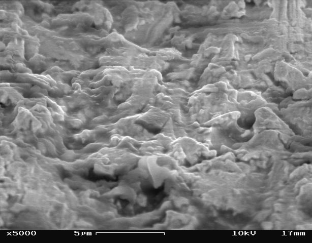
Fig 15. Bronze tool |
||||||
|
Bronze tool after 6 grinding cycles of BK7 crown glass.
Coated with gold for 30 seconds, in 50 millitorr
vacuumed sputter machine. The resin tool was left out from this stage onwards due to technical difficulties. |
|||||||
|
|
|||||||
|
||||||||||
|
||||||||||
|
|
||||||||||
|
|||||||
|
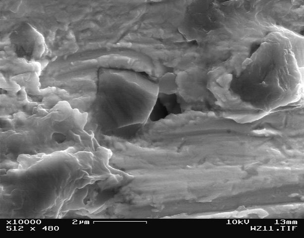
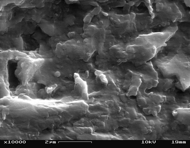
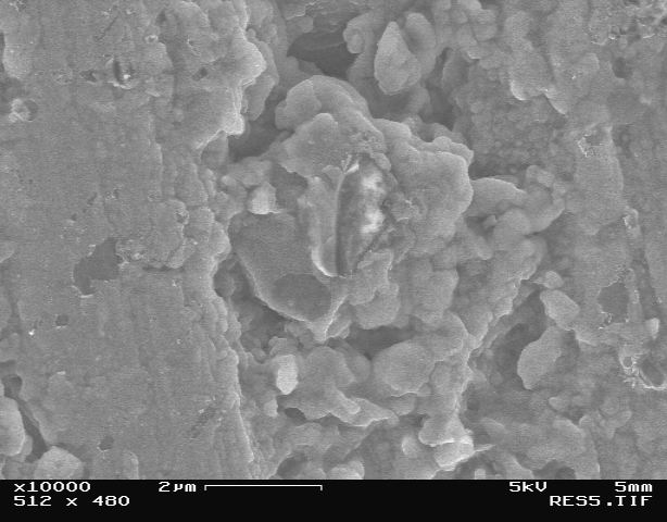
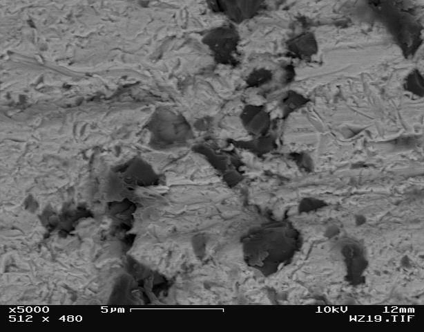
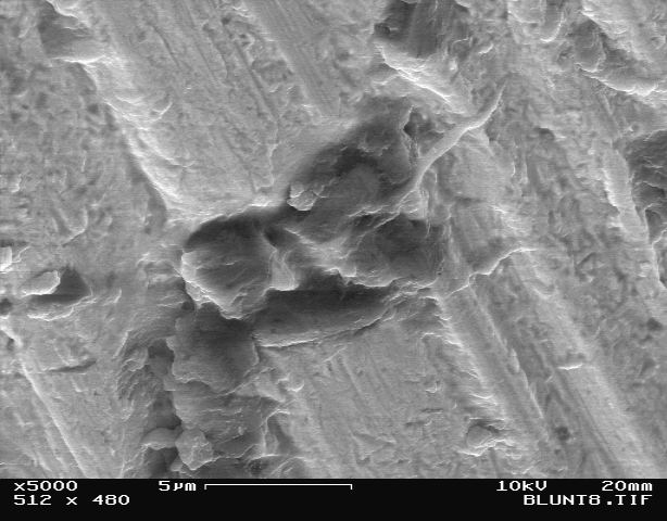
Fig 21. Bronze tool after 8 cycles
These images were taking using a BSE detector and colored for a more "alive" version than the normal black and white (More...). |
||||||
Summary of Observation
Observation of the tool face after a variety of grinding and dressing operations provided characteristically different surfaces for each case. Dressing operation were conducted with a 2-4 mm bronze and resin tools, and 1500 grit dressing stick. Differences can be clearly observed from the dressed tools images, showing low (or none) diamond protrusion, with the diamonds appearing almost flush with the matrix surface, similar to SEM observation results discussed by Gough et al.
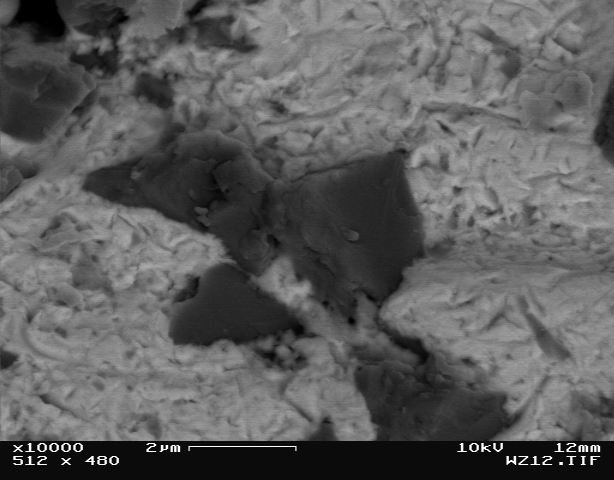
Grinding tests images show that the matrix material appears smoother with more tracks evident on the surface as grinding cycles increased. Diamonds are sticking out more from the surface with a noticeable sharper form after 6 cycles compare to 3 cycles test. 8 cycles test created a tool surface with moderate protrusion heights but significant diamond blunting, producing flat tops on the diamonds. The matrix also displays a smoother texture likely due to smaller particles impacting the surface [5].
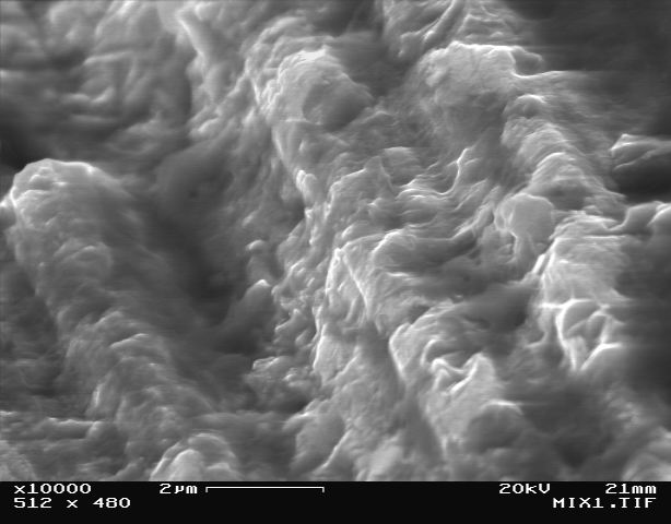
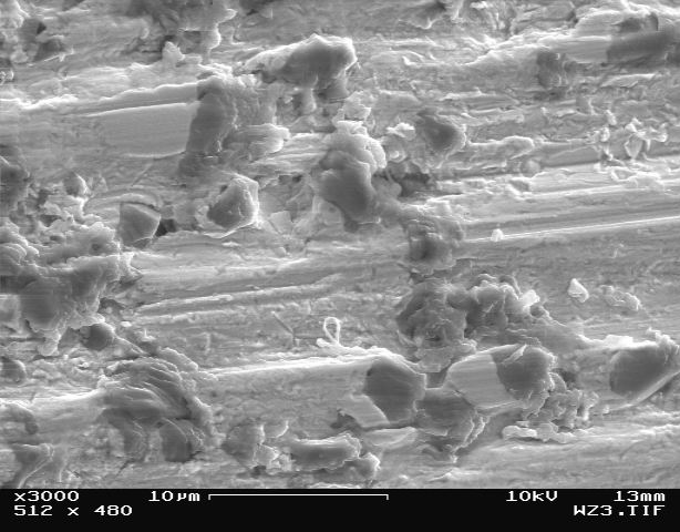
Fig 22. Work zone tracks visible after 8 working
cycles.
In-lense and In-chamber detectors mix signals.
Conclusions
As experimental data show, a blunting of the diamond grains occurs during grinding with the formation of very pronounced wear areas on some of them. The blunting of the diamond grains also leads, in particular, to a lowering of the grinding efficiency if it is not accompanied by the simultaneous removal of the blunted grains and their replacement by new ones. As a result of binder wearing the tool loses it effectiveness. Consequently, the dependence of grinding efficiency on the amount of wear of the diamond grains must be taken into consideration both in the construction as well as in the development of techniques for using the tool.
Reference
[1] A. Broese van Groenou, "Some Results on the Wear of a Bronze-Bonded Grinding Wheel", Science of Ceramic Machining and Surface Finishing II (1979).
[2] Miller, Michele and Handigund, Prasamm, "Abrasive Wear and Forces in Grinding of Silicon Carbide", Michigan Technological University (2000).
[3] Miler, Michele and Kakumanu, Thrinath, "Wear and Self-Dressing of Resin Bound Grinding Wheels", Michigan Technological University (1999).
[4] D. Gough, The Use of Tool Probing for Process Optimization and Wear Analysis in Deterministic Microgrinding, Master Thesis, University of Rochester (2003).
[5] J. S. Taylor, LLNL
[6] P. Funkenbusch, COM Summer School (2001).
[7] H. Karow, Fabrication Methods for Precision Optics, Wiley Series in Applied Optics, p. 309 (1993).
[8] Moore Nanotechnology Systems, LLC, 426A Winchester st., PO Box 605, Keen, NH 03431-0605 USA.
Acknowledgments
I would like to acknowledge the following people contributing there valuable time and experience to the completeness of this study - Sha Tong, Edward Fess, Enbal Shafrir, Zami Naim and Brian McIntyre.
Please enter any comments, criticisms, questions,
etc.
below.
Your name:
Email address: