Daguerreotype TEM Sample Preparation Using
Gas Injection and Focused Ion Beam Milling
Alex Mann1, Brian McIntyre2, Ralph Wiegandt3
1URnano, Department of Physics & Astronomy
2Department of Optics, University of Rochester, Rochester, NY 14627, USA
3George Eastman House International Museum of Photography and Film, Rochester, NY 14607, USA


Once the sample has been released, how is it moved to the TEM grid?
Using a micromanipulator probe (brought into contact with the now free standing sample) and a technique known as a Gas Injection System (or GIS), a very low flow of platinum-organic gas is introduced locally by means of a hair-sized capillary. As the FIB (and, to a lesser extent, electron) beams pass through the gas cloud the organic component of the gas is dissociated allowing the Platinum to deposit on across a region scanned by the beam.
As the GIS capillary comes in at a working distance of 5mm, it is critical that the beam coincidence is setup at 5.1, to all sufficient clearance so as not to impact the capillary. The close proximity can easily be observed in the image below. |
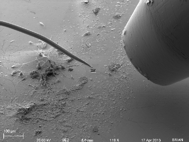
Micromanipulator (left) and GIS capillary (right) in proximity to the TEM sample.
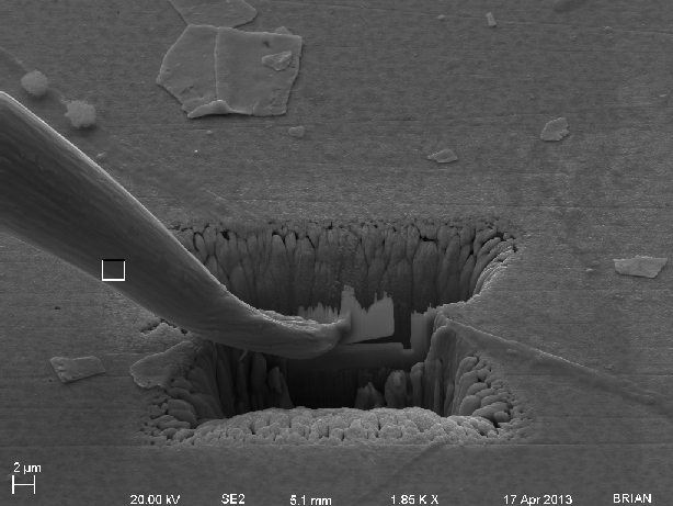
Micromanipulator welded to the TEM sample using the GIS Platinum deposition.
|
With the TEM sample welded to the end of the micromanipulator, the stage was dropped away leaving the sample and micromanipulator suspended in free space. The stage is then relocated to bring the TEM grid up under the sample.
|
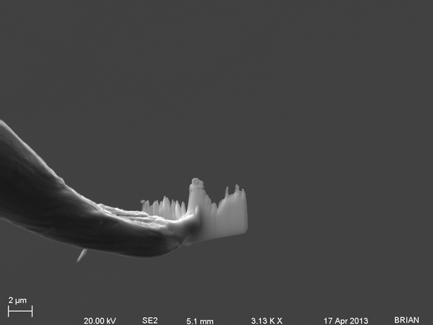
The center grey box indicates the area selected for milling.
|