Daguerreotype TEM Sample Preparation Using
Gas Injection and Focused Ion Beam Milling
Alex Mann1, Brian McIntyre2, Ralph Wiegandt3
1URnano, Department of Physics & Astronomy
2Department of Optics, University of Rochester, Rochester, NY 14627, USA
3George Eastman House International Museum of Photography and Film, Rochester, NY 14607, USA


![]()

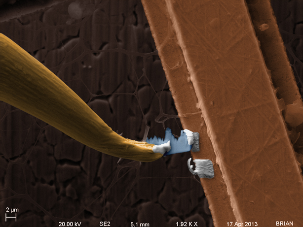
How is the sample attached to the TEM grid? In the image below, an extra platinum square can be observed. This was due to a shift in beam coincidence. The FIB beam (used to dissociate the Platinum) was impacting slightly off from where the electron beam scanning area was. This was corrected for the final deposition, which can clearly be seen on the TEM sample. |
|
How was the sample released from the manipulator? There were some new challenges at this point, however, specifically due to the angle at which the milling must be done. Ideally, the beam would cut through the Platinum perfectly parallel to the sample. Since that was not feasible in this situation, part of the sample itself was also cut in the process. Due to the precision required, 50nA was used for two reasons: Firstly, lower current results in longer mill times and thus more controlled ablation. Secondly, the 50nA aperture is the same used for imaging with the FIB beam, which eliminates a potential source of error from misaligned FIB apertures. |
|
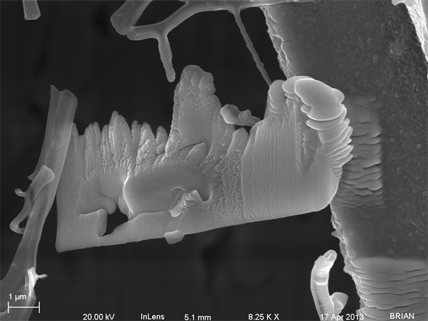
How did the sample turn out? Some considerations that could be implemented include milling a thin "handle" off the sample to attach to the micromanipulator. This could then be used as a support for the sample, to be cut once the final welding is complete. This would reduce the potential for milling through the sample during the final cut. Secondly, this would also allow for the sample to be relocated at a more precise angle. Another aspect that could be employed would improve the sidewall generation of the sample - over/under tilting during the initial ablation process. This will help maintain parallel sidewalls and not result in a taper effect with more material remaining at the bottom. |
|