Problem Statement
This project aims to create a 3D printed lens housing for an f/2.8 system that incorporates seven elements. This system was compared to an aluminum housing designed by Edmund Optics to see if it could be used for rapid prototyping assemblies.
Team Members
 |  |  |
| Brennan Hong | Ryan Malarkey | Victoria Usachev |
| bhong3@u.rochester.edu | rmalarke@u.rochester.edu | vusachev@u.rochester.edu |
| Scribe | Document Handler | Project Coordinator |
Customer
Nick Smith – Edmund Optics
Faculty Advisor
Ethan Burnham-Fay – Mechanical Engineering Department
Vision
The objective of this project is to create a 3D printed lens housing for a larger imaging assembly in order to better understand how well it could be used for rapid prototyping of imaging systems. Last year, a design was successfully created to hold an imaging system to its performance metrics, and this project allows us to continue researching the barriers of 3D printing optomechanical housings and in what situations the method would not meet specification or reach a downfall. Being able to determine the performance tradeoffs when using 3D printed mounts would allow for much faster turnaround times, and can give engineers a better idea of when to use 3D printed housings over aluminum housings manufactured through traditional machining methods. We will measure MTF values to compare our system to the standard housing produced by Edmund Optics. We can then test different designs and factors to see how they affect the system. This would allow us to prove that 3D printing is a viable way to prototype a lens housing.
Printer and Material Choices
- Printer: Stratasys J35 Pro 3D Printer
- Has the ability to print with three different materials separately or simultaneously
- Resolution of 150 um
- Material: Stratasys’ VeroUltra BlackS
- Resin that does not require finishing after printing
- Drastically decreases manufacturing time for the prints
Design Process
When designing the barrels, we decided to design both a poker chip and a drop-in system in SolidWorks to be able to compare how both systems operate when 3D printed.
The drop-in design is based off the mechanical system provided to us by Edmund Optics and consists of dropping optical components into a mechanical housing without requiring complex adjustments. The purpose of this study was to see how similar we could keep our 3D printed version to the mechanically machined version. The poker chip design, also known as a subcell assembly, consists of individual lens elements to be mounted in separate, but precisely aligned slots that ensure an excellent optical axis alignment and centering accuracy.
The biggest issue when designing these systems is that in every print there is some form of shrinkage. This is typically due to the part cooling down throughout the printing and is unavoidable. Therefore, we had to compensate for the shrinkage by increasing each diameter within the system. We 3D printed a preliminary design to test how much it was affected by the shrinkage, and found that the inner diameters shrunk by about 0.3 mm. This was taken into account when moving forward in the design process.
Drop In Design
For the first iteration of the drop in design, when placing the lenses into the barrel, we noticed that the larger lenses would move whenever the system was tilted or shook. This meant that we had to compensate for the loose elements by decreasing the diameters in the barrel by 0.05 mm. After reprinting this system with the changes to the diameters, the lenses fit more comfortably, which gave us confidence that the lenses were fully seated when testing would occur.
The retaining rings and aperture stop were printed for this design as well. However, the outer retaining rings included threads that were too small for the printer to be able to successfully print, so “pull tabs” were added on the sides for easy removal when needed. These rings were also printed with a small gap to be able to firmly place the rings on the edges of the lens without falling out.
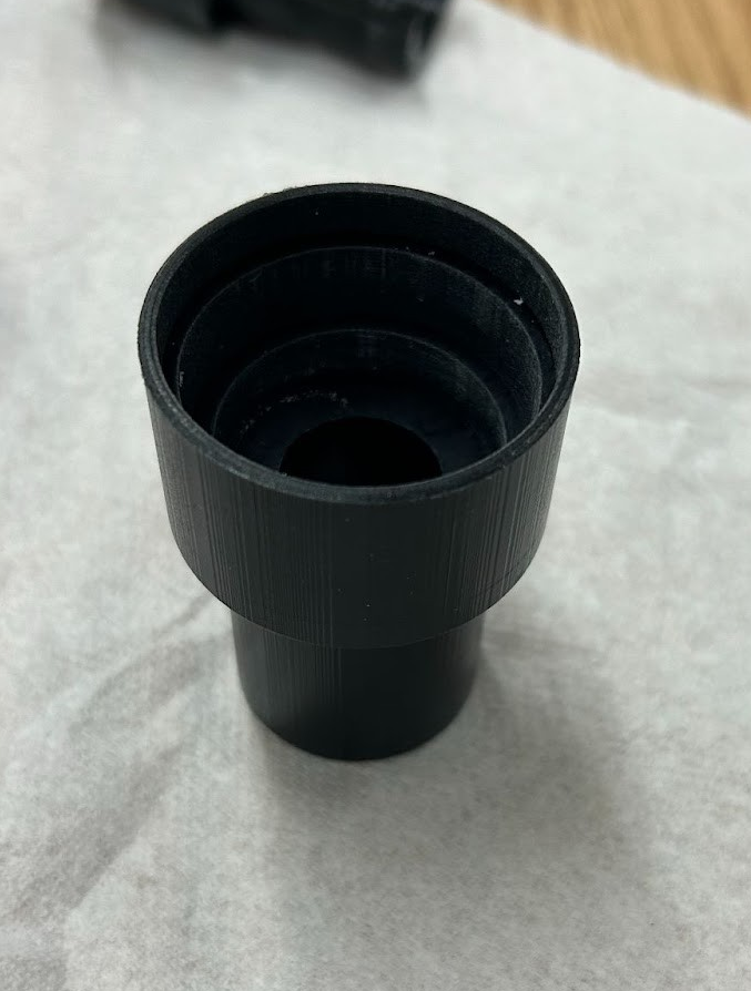
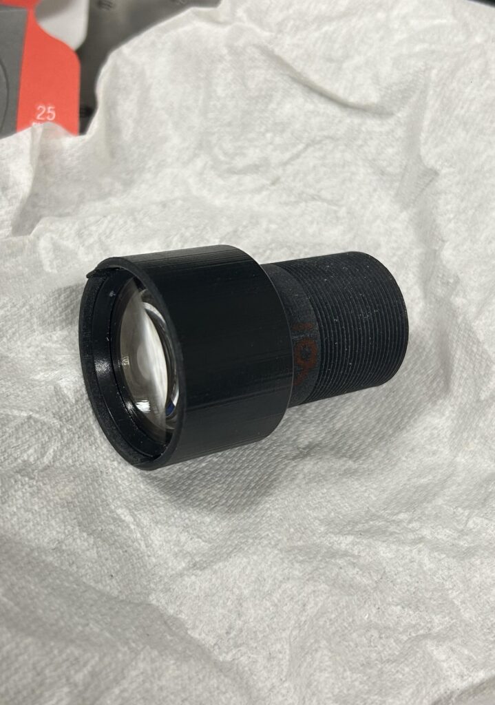
Figure 1 & 2: Images of 3D printed Drop-In design
Poker Chip Design
When first designing this type of housing, we measured the edge distances between the lens elements to give us a baseline of where they should be seated. We then extruded and cut the lens shapes out of the housing the approximate distances apart from where they were seated in the aluminum housing. This method will be helpful in the long run by eliminating the need for retaining rings, which usually provide spacing between elements, as well as the aperture stop, which we can just print within our housing.
After our first print, we noticed that some lenses did not fit correctly in the spaces we had allotted for them, which was most likely due to the shrinkage and resolution of the 3D printer. We took note of these misalignments and incorporated them into our next iterations. We kept on adjusting the designs until all our elements were snug and the housing would close completely. From then, we began testing on the LensCheck.
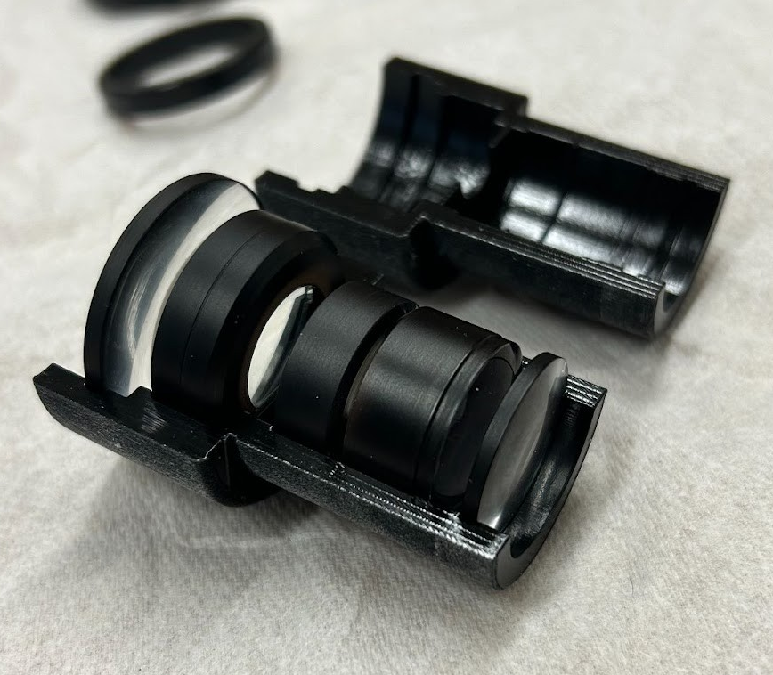
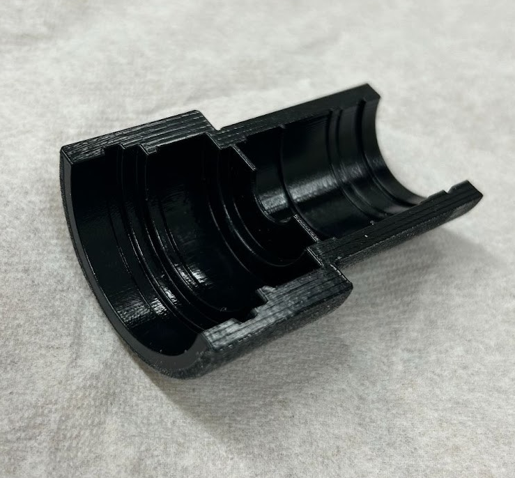
Figure 3 & 4: Images of the 3D printed Poker Chip design
C-Mount Study
We decided to attempt a print of a C-mount to investigate whether the printer had the resolution to print the threads, which are 32 threads per inch (0.794 mm pitch), designated as “1-32 UN 2A” in the ANSI B1. On our first pass attempt, we were able to successfully print a C-mount and mount it onto a CCD camera very firmly.

Figure 5: Printed C-mount screwed onto a CCD camera.
There was a bit of chipping off the edge of the mount due to us jamming the mount farther than was necessary onto the CCD camera, but overall, the threads held and did not break, and we were able to smoothly twist them on and off the CCD camera. This allows for focus adjustment of the lens when necessary.
Testing Results
In order to compare our results with the aluminum housing that Edmund Optics provided us, we measured the effective focal length and the MTF of the aluminum housing to gather a baseline data to compare against. This was done using the Optikos Lenscheck. The EFL and MTF were subsequently measured for the 3D printed housings. The MTF was measured at five different field points to fully determine success of the performance of the 3D printed mounts.

The system was placed onto an optical mount, then 5 EFL measurements were taken, along with a set of MTF measurements. At first, we struggled to obtain accurate MTF measurements due to the large field of view of the camera. When running through the measurements, the Lenscheck continually lost the spot as it tested the larger field of views. In order to fix this, we added intervals of fields separated by 1 mm to keep the spot in the middle of the crosshair. We also increased the crosshair to ensure that the entire spot was encapsulated during the through focus measurements. The fields that we wanted to measure were the on axis field, 4 mm, 5.5 mm, 8 mm, and 10.8 mm.
Furthermore, we increased the performance of our measurement by increasing the size of the pinhole used for the measurements. This is because with the previous pinhole size we were using, not enough signal was reaching the detector, leading us to obtain incorrect results.
EFL Results
| Theoretical Values | Aluminum | Poker Chip | Drop In | |
| Average EFL [mm] | 50 | 49.97 | 50.04 | 49.99 |
| Standard Deviation [mm] | N/A | 0.016 | 0.046 | 0.024 |
Table 1: Effective Focal Length comparison between Edmund’s housing and our 3D printed housings
MTF Results
The original system we measured struggled to pass for the last two field points of 8 mm and 10.8 mm, and even with multiple testing configurations and runs, we were not able to make it completely pass specification. Therefore, we used the MTF that we found as our baseline to compare our designs against.
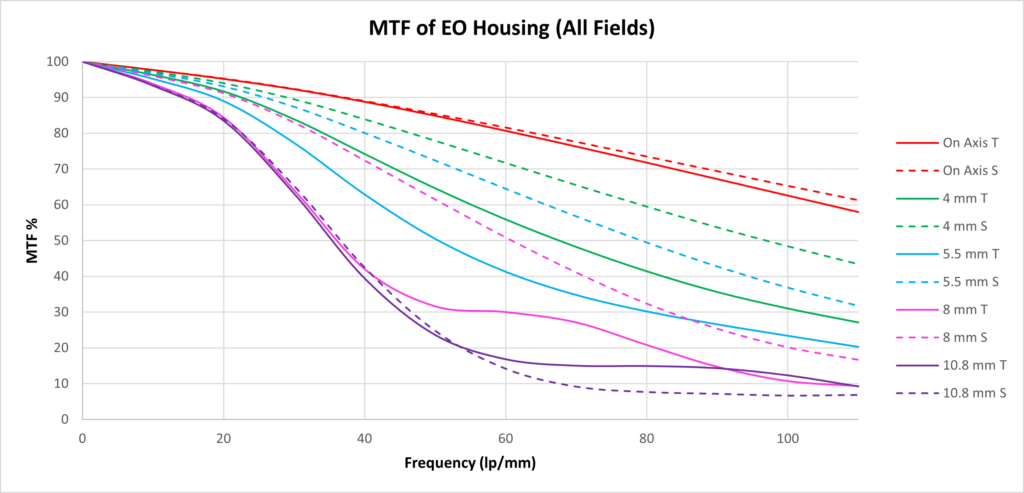
Figure 7: MTF plot of the Edmund aluminum housing
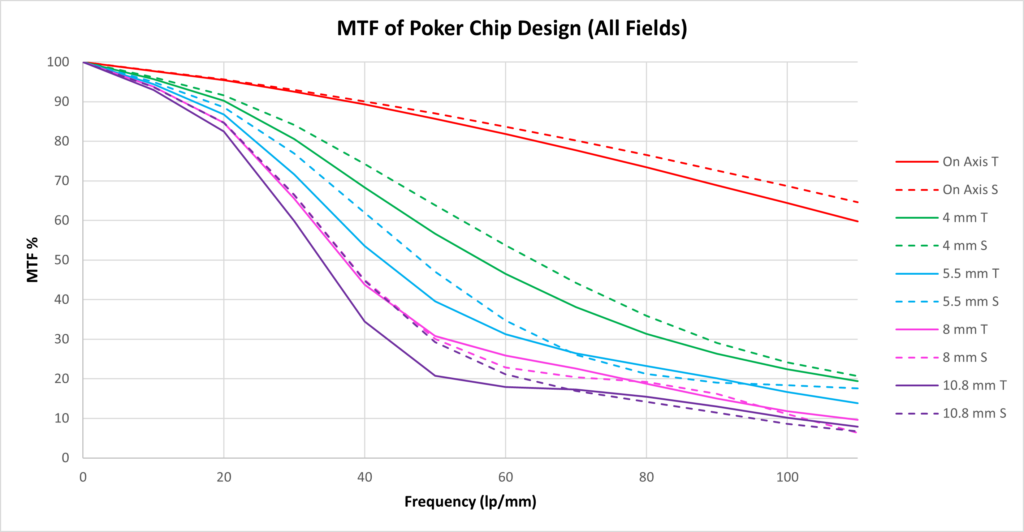
Figure 8: MTF plot of the Poker Chip housing
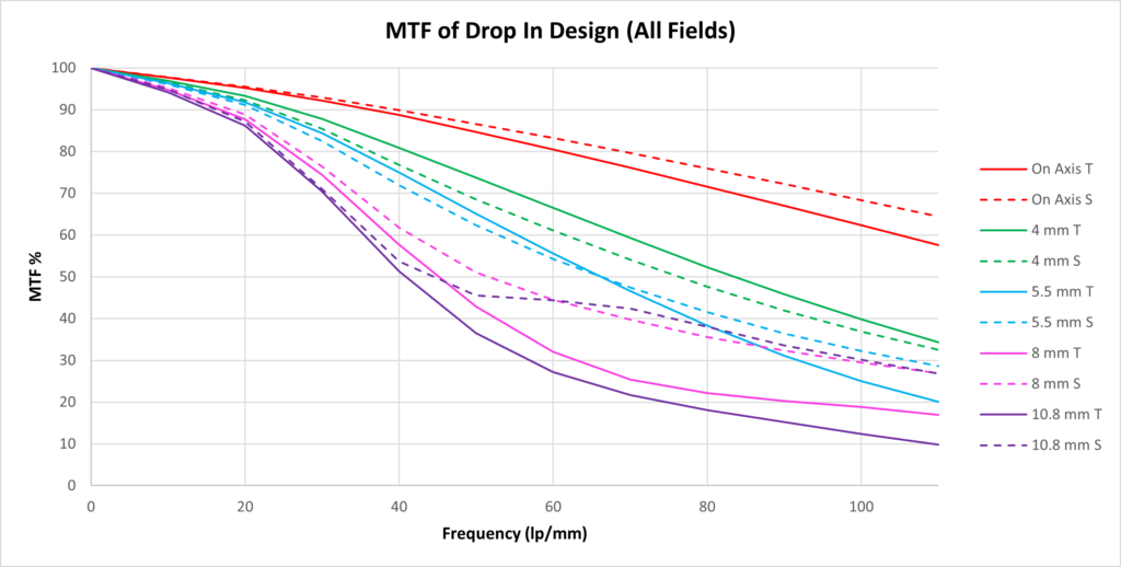
Figure 9: MTF plot of the Drop In housing
Conclusion
With these results, we have found that both of our 3D printed designs compared to the Edmund aluminum housing quite well. From the EFL results table above, the drop in build had the best average EFL when compared to the other two (poker chip and Edmund’s aluminum). However, the Edmund’s housing had the most consistent results with the lowest standard deviation.
When comparing the MTF plots, we have found that our drop in design behaves very similarly to the Edmund aluminum housing, surpassing the baseline MTF that we took for the aluminum housing, even though it does not meet specification at the tangential 8 mm and 10.8 mm field points. In the sagittal plane, all fields passed with the first four fields being above 20% contrast at 110 lp/mm and the last field point being above 10% at 90 lp/mm. The poker chip design, however, has a slightly worse performance than the other two systems, and did not pass specification for three of the field points. Therefore, in our experiment, it seems that drop-in designs may work better when 3D printed over poker chip designs. This may partially be as a result of the shrinkage at or around the aperture stop, or shrinkage of the distances between the lenses.
Acknowledgements
We would like to extend a huge thank you to our customer contact Nick Smith from Edmund Optics for providing us with the materials required for the project, as well as his constant support and attention. We would also like to thank Jim Alkins, Ed Herger, and Ethan Burnham-Fay for their assistance throughout the year. Finally, we would like to thank Wayne Knox and the Institute of Optics for this opportunity to learn and grow within our industry.