Mission Statement
The goal of our project is to create a Do-It-Yourself (DIY) telescope that provides an engaging and educational experience for kids. The telescope will come fully disassembled, empowering kids by giving them the opportunity to put it together and align it themselves. The telescope has been design with a strong emphasis on modularity and standardization.
Modularity: The various parts can be easily separated and swapped for ease of storage and ease of expansion. How cool would it be to add tracking motors and a deep-space imaging camera, or swap out your Newtonian optics for Cassegrain optics, all without changing the base product? This reduces the price for expansion and increases the value of the educational experience.
Standardization: The telescope has been designed to minimize variety of parts and hardware wherever possible. This will not only make manufacturing simpler, but will also make the assembly process easier for a child user. For example, there are only 3 bolts sizes used throughout the entire design.
Additionally, the telescope will come with an array of instructions, lessons, and activities to help lead them through the assembly process.
The Optical Design
The optical design consisted of developing a set of specs for the telescope, based on what we wanted to see, completing a design study for different aperture sizes to compare performance and cost, and creating a design for the base model product. We chose to go with a Newtonian design form for this telescope to maintain a lower cost and to ensure ease of alignment by the user. In the base model of the kit, the users will be able to use the telescope in both a visual and sensor based configuration. This will allow the telescope to be used as a classical scope or with a camera to introduce the users into the world of astrophotography so they can share some of the cool celestial objects they are viewing.
The Opto-Mechanical Design
The mechanical design involved in-depth CAD modelling focused around creating a unique design and working with optical and mechanical tolerances to bring the telescope into reality. The work that has been done is too expansive to summarize all of it here, but if you are interested in learning more, please feel free to visit the Mechanical Engineering Log through this button:
The Primary Mount
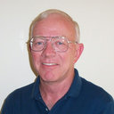
The primary mount comes in three major pieces when additively manufactured, but this can be reduced to two when subtractively manufactured.
The first piece is the primary mirror cell. This is a three-point mount with the mounting points at 70% diameter of the mirror. The mirror is affixed to this piece using Silicon RTV epoxy.
The next piece, which attaches to the primary mirror cell using bolts, is the kinematic vee-plate. This plate features a 3-vee kinematic mount meant to exactly constrain the mirror and allow for a thermal datum that lies on the optical/mechanical axis of the telescope.
The kinematic vee plate is tensioned, using springs, onto three lead screws. Each of these screws lie in one of the 3 vees and are all attached to the primary mount tube plate. These screws are used to adjust the tip/tilt of the mirror and also allow for some piston along the optical axis. The tube plate, on top of holding the rest of the assembly, acts as the interface connecting the assembly to the telescope tube.
The Secondary Mount
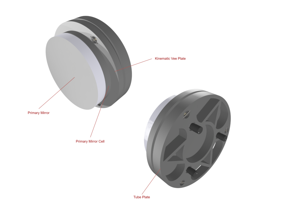
For this project, we chose to employ a single post secondary mounting scheme. This is because it was the quickest and easiest mount for us to produce for our prototype given our limited time window. Furthermore, we felt that having a single post will give the child users the easiest experience with aligning the secondary mirror to the center of the telescope tube.
The design features many parts, but we will begin with the base. The base is a triangular piece with its face oriented 44 degrees relative to the face with the tilt adjustment knob in it. It is 44 degrees because this allows the mirror to have dynamic range before and after its ideal angle of 45 degrees relative to this face. The base is attached to the secondary mirror cell, to which the secondary mirror is affixed. The secondary mirror cell is also a three point mount that uses Silicon RTV epoxy to hold the mirror down to the points.
The secondary mirror cell is affixed to the base using a piece of steel shim stock that acts as a hinge, thus allowing for rotational adjustment, which we call tilt in this case. Tilt can be induced in the mirror cell using the tilt adjustment knob.
The base is attached to the tube by the single post which is held by the outside mounting plate. The outside mounting plate, in combination with the inside mount plate, hold the secondary mirror assembly to the tube. Also attached to the outside mounting plate is the tip arm. The tip arm is press fit around the single post and held down to the top adjustment knob by a screw with a compression spring (not pictured). The tip adjustment knob can be turned to adjust the tip of the mirror, which is a rotation perpendicular to tilt.
The Focuser Module
The focuser module in this revision of the prototype is gear driven. In future revisions, the embodiment of this gear driven system will be different or it may be swapped out for a friction-driven system.
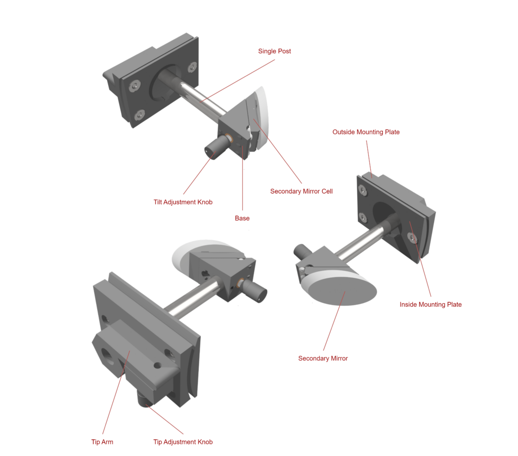
The base of the whole focuser module is the outside mounting plate. Combined with the inside mounting plate, they hold the focuser module to the tube. More importantly, the outside mounting plate holds the end effector holder, which holds the end effector whether it be a camera (for astrophotography) or an eyepiece (for visual inspection).
The focusing happens when the focusing gear is rotated which engages with a rack gear on the bottom of the end effector holder (this cannot be seen in these renderings).
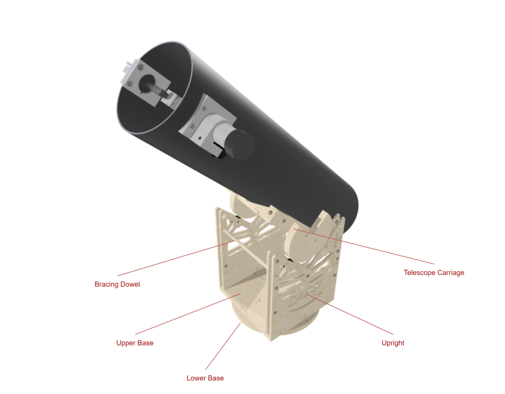
The Telescope Mount
The telescope mount is one of the most integral pieces of the telescope as it is what enables the telescope to be used (because trying to use this handheld would be near impossible).
The first two pieces to direct your attention to are the upper and lower base. Between these two pieces is a turntable that allows the telescope to rotate along its azimuth axis.
The upper base also holds the uprights. The uprights are two pieces of CNC-cut wood that are strutted together in seven locations. The uprights also house bearings that the telescope carriage sits on and that help control the altitude axis. The telescope carriage is the piece that the telescope attaches to.
The bracing dowels keep the mount from pulling apart or pushing together, a motion which can damage the mount.
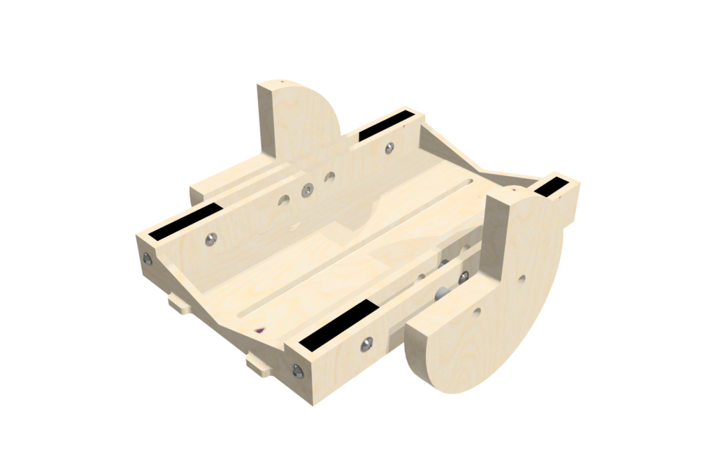
A closer look at the telescope carriage:
The Opto-Electronics
The opto-electrical portion of the design incorporates a CMOS camera into the telescope system. Both cost and capabilities were important factors in deciding which camera to utilize. For the original kit, due to cost, our camera capabilities were limited to planetary and lunar imaging cameras. The idea is that expansion packs will be available for users to, for example, purchase an expansion pack that includes a more expensive camera capable of imaging deep-space objects.
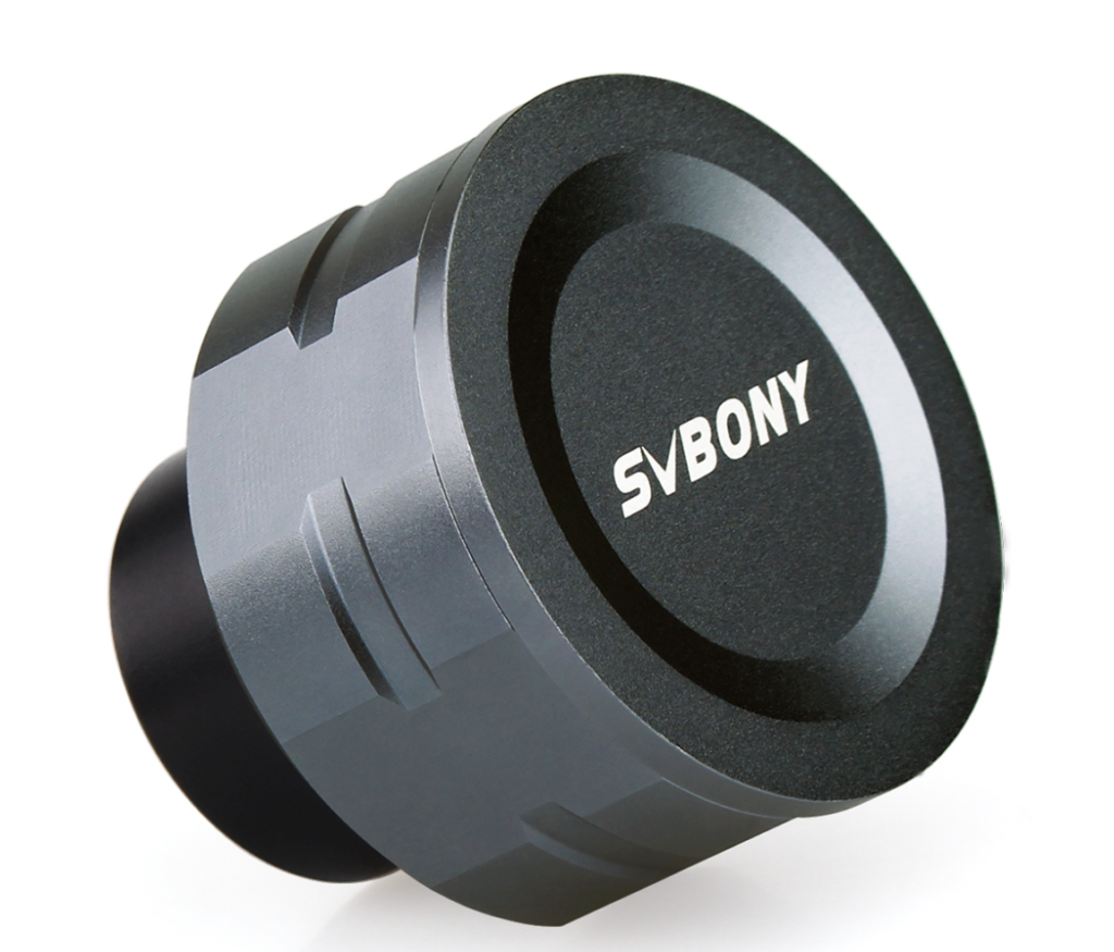
The Camera
For the prototype, we decided on using the SV105 model camera from SVBony. This camera is affordable and designed for beginners with capabilities of lunar and planetary imaging. The camera uses a CMOS sensor with a 1/ 2.7” sensor and has a pixel size of 3 microns with 1920 x 1080 active pixels.
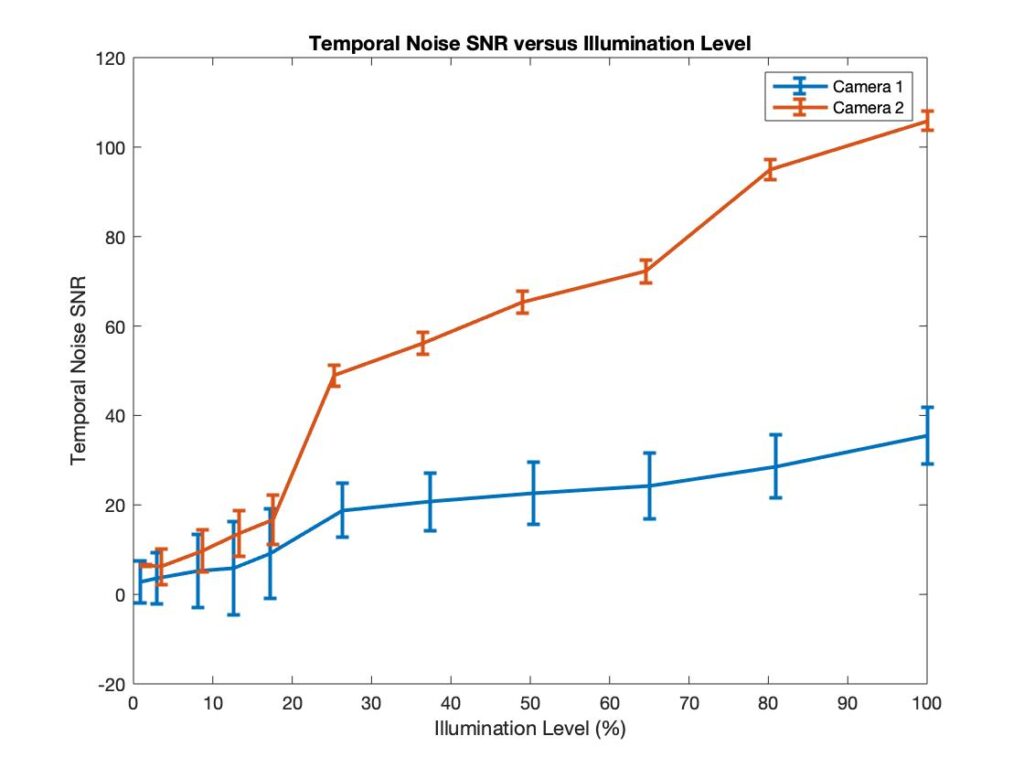
Camera Characterization
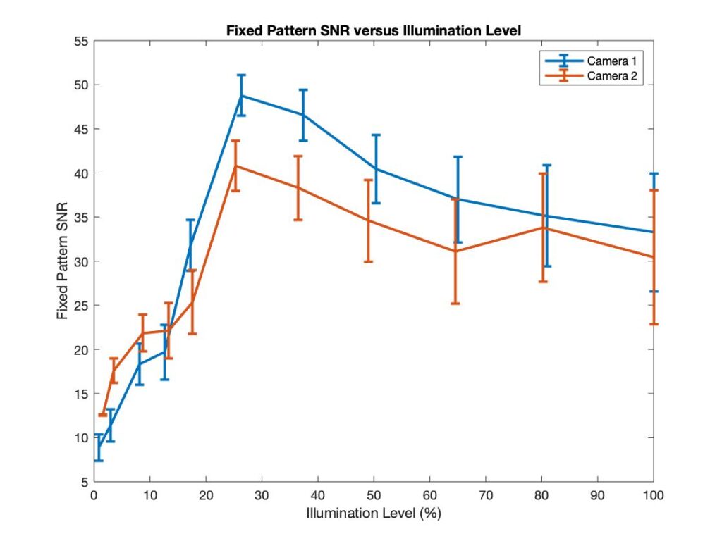
After selecting and purchasing two SV105 planetary cameras, the group characterized the cameras by performing different tests to ensure that not only the cameras performed similarly, but that they had the capabilities we expected for our telescope. To characterize the SV105 camera, an OECF (Opto-electronic conversion function) focal plane method test was performed on both cameras. To do so, SharpCap astronomy software was used along with an integrating sphere that uniformly illuminated the camera sensor. In this test, the fixed pattern noise and temporal noise were analyzed according to the ISO 15739 standard to calculate the signal to noise level on the sensor. By taking sets of images at different illumination levels, we were able to analyze the noise and furthermore, the signal to noise ratios.
It was also important to characterize the sensor by calculating the number of photons incident per pixel. Ideally, our CMOS sensor would perform linearly with the number of photons incident increasing as the illumination level increased. A Newport radiometer was used to provide the output power in Watts as we fluctuated the illumination level. This reading from the radiometer was calibrated to provide an irradiance value in W/cm2 which was then used to calculate the power incident on each pixel, the energy per pixel, and finally the number of photons incident on each pixel. The figure below shows the linear response of illumination and incident photons.
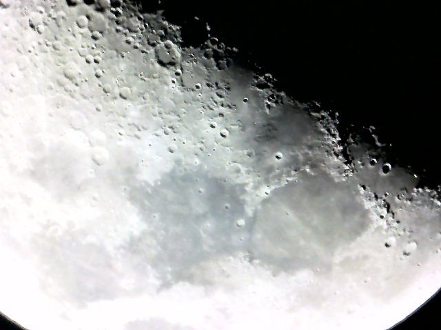
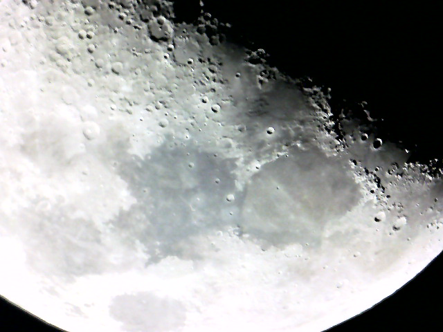
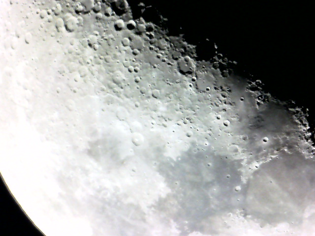
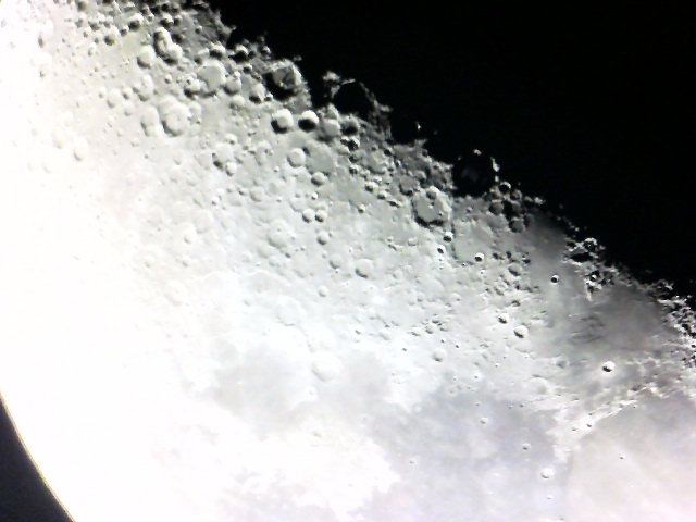
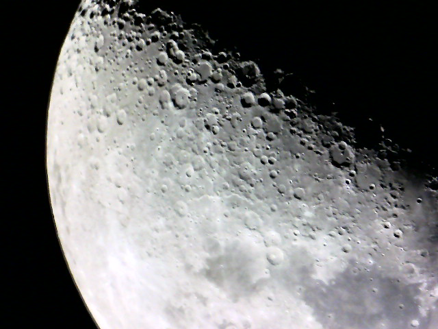
The Images
Below are images captured of the moon using the SV105 camera:
The Educational Materials
The educational materials, as previously mentioned, will lead the user through the assembly process using a variety of instructions, lessons, and activities aimed at getting them excited about STEM. There will be hands-on exercises, lessons on the basics on optics, lessons that encourage the user to question why things are a certain way in a complex optical assembly, and many more.
At this time, we have completed some sample educational materials to give you a feel for what they will look like. You can access them on our project documentation page here: