Team
- Julia Esen
- Jonathan Friedman
- Eric Bang
Mentors
- Dennis Briggs, Danbury Mission Technologies
- Professor Chris Muir
- Mike Pomerantz
- Jim Alkins
- Ed Herger
- Chris Pratt
Abstract
Optical CNC grinding processes lack quantitative data on cutting forces, making process control difficult and dependent on operator intuition. To address this, the team collaborated with Danbury Mission Technologies to develop a fixture system that mounts optical workpieces to a load cell for real-time force measurements during edging operations on an Optical CNC machine (Opti-Pro SX-50). The system was designed to specifications within the spatial envelope available within the machine, allow for interchanging of optics, and allow three-axis force resolution within ±7.8 pC/N in Fx and Fy, and ±3.7 pC/N in Fz. The team began by establishing key requirements and independently designing candidate fixtrues, which were evaluated using a Pugh Matrix. The selected design was modeled in full detail using Siemens NX and fabricated from aluminum 6061. The optic was bonded using UV-curable Dymax OP-GEL-29, chosen for its ease of use, stability, and documented properties which were modeled in FEA. Mechanical analysis included finite element modeling of stress in the optic, tolerance analysis to achieve concentric alignment within 10 microns, and a fatigue assessment of the set screw system under cyclic loading. The final design met all performance targets and was tested across multiple tool paths, successfully capturing repeatable force trends. Final deliverables included the physical fixture, validated test data, a full report, and a documented theory of operation. The resulting system offers a scalable method for acquiring precise force data in optical grinding and lays the groundwork for more data-driven process improvements.
Problem Definition
This project will study the forces exerted on a workpiece optic during CNC grinding procedures of edging. Currently, there is a lack of data for optical CNC grinding loads, leading to process improvements mostly driven by tacit knowledge. Understanding the forces experienced throughout common tool paths in optics manufacturing can provide a systematic approach to improving precision and minimizing defects.
Requirements, Specifications, Deliverables
Table 1
Requirements
| Requirement | Description |
| 1 | The load cell must capture accurate load data exerted by the CNC tool. |
| 2 | The fixture must hold the optic/workpiece fixed. |
| 3 | The workpiece must be interchangeable in the fixture. |
| 4 | The fixture accommodates the maximum-sized optic. |
| 5 | The fixture accommodates machine paths/cuts of edging. |
Table 2
Specifications
| Specification | Description |
| 1 | The forces measured include 3 DOF. |
| 2 | The accuracy of measurements is within 1 N. |
| 3 | The minimum and maximum force the load cell can detect are 0 N and 100 N. |
Team-created project planning tools will attain the deliverables of this project through a WBS and CPM. The main deliverable components from the WBS include the following: load cell fixture, experiment design, testing, post-process load results, and further documentation. The complete breakdown structure is located in the appendix. An excel sheet of the WBS with the CPM was additionally created to associate estimated times for each activity. Each activity accomplished is organized to be conducted by a designated field: technician, design engineer, analyst, and software engineer. The expertise with the largest dedicated time of ~210 hours is the design engineer. The total time to execute the project is 360 hours at a cost of $23,550.00. A CPM chart was constructed with an identified critical path length of 83.00 hours with complete working staff. If one engineering resource is lost, there is an additional plan on how the WBS & CPM will be modified and this reduced the critical path length to 77.00 hours. Additionally, if an unforeseen circumstance eliminated fabrication time, a modified WBS & CPM plan is created to drive further analysis at a critical path length 77.00 hours.
Table 3
Deliverables
| Deliverable | Description |
| 1 | Load Cell Fixture |
| 2 | Validata Test Data |
| 3 | Technical Report |
| 4 | Theory of Operation Manual |
Concepts
For the project each team member created two preliminary designs: a glue plate and a base plate. Each team member created a pattern of groves on the face of the glue plate, allowing glue to fill this pattern and the optic to be adhered to the plate. This base plate is a fixture that allows interchangeable glue plates to be attached to the load cell.
Base Plate concepts:
One concept design is a threaded mount. The design intention is to offer an accessible way to quickly hand-twist the optic plate in and out of the fastened base plate connection to the load cell. This will save time handling during the extensive experimentation process. One design concern is during grinding operations, the vibrations induced may translate an axial load down the threaded shaft and cause the fixture to loosen, risking the optic.
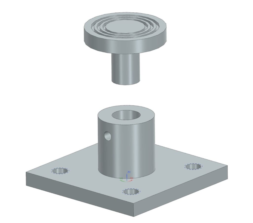
The second concept design for the base mount consisted of a shaft from the glue plate fitting into a sleeve and being tightened into place by a set screw. This design was focused on ease of manufacture as well as convenient interchange of parts.
The third concept design for the base mount utilized a chuck that would be purchased. The chuck would then be mounted to the load cell and used to grip the shaft of the glue plate. This design was focused on accurate and reliable holding of the glue plate.
One concept for the glue plate design was striped grooves [6]. Striped grooves were designed on the optic plate to workpiece interface to allow excess bond glue to escape. The surface area covers 95% of the workpiece diameter of 1.5” to allow surfacing and edging procedures.
Another concept for the glue plate was a cross-hatch pattern. The cross hatch pattern allows for glue to escape and to have a more consistent distribution while being easy to manufacture.
The third concept for the glue plate was a radial pattern design. This design allowed for the most even distribution of glue, but the design complexity may pose some challenges in manufacturing.
Concept Selection
Pugh Matrix for Fixture Concepts
| Threaded (Baseline) | Set Screw | Purchased chuck | |
| Cost | 0 | 0 | – |
| Lead Time | 0 | 0 | – |
| Ease of manufacture | 0 | + | 0 |
| Compactness | 0 | + | – |
| Ease of Swap | 0 | – | – |
| Reliability during testing | 0 | + | + |
Pugh Matrix for Glue Geometry
| Cross-Hatch | Stripes | Radial | |
| Glue Escape | 0 | – | + |
| Max Stress in glue | 0 | – | + |
| Ease of manufacture | 0 | + | – |
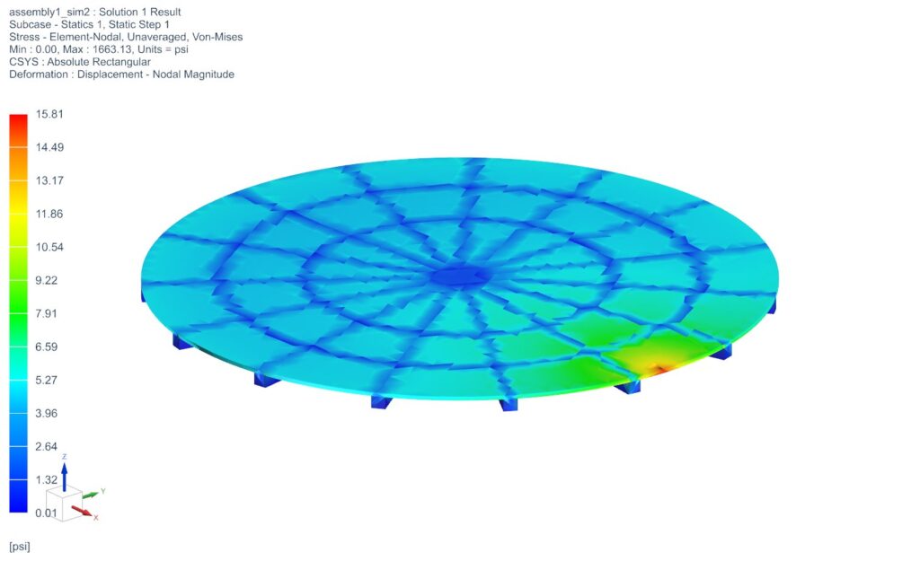
A quantitative study was conducted to evaluate the mechanical performance of three proposed fixture groove designs — a hatch, cross hatch, and a radial design — used to bond the optic to the fixture, under loads that were representative of the force components in CNC edging and surfacing. Further information on how the study was conducted and the results/discussion is featured in the following section.
The team decided to pursue a variation of the set screw design, incorporating the idea of three points of contact while maintaining ease of manufacture. The shaft of the glue plate is pushed against by the set screw into a v shape backing, providing three points of contact.
The Glue Escape criteria describes the ease of distribution of glue across the face and the ability of excess glue to evacuate.
The glue plate concepts were characterized by different patterns etched into the face. The stripes pattern was the easiest to manufacture but had the highest stress and there were concerns about glue distribution. The cross hatch was slightly harder to manufacture (would need to reposition on the mill), but slightly lower stress and better glue escape due to the channels being interconnected. The radial design performed the best in the simulation, by having the best glue escape and distribution, but due to the design would need to be machined on both the mill and the lathe, or CNC machined.
The final decision made was the radial groove design on the glue plate. The general glue plate body was fabricated on the lathe and the radial groove design was etched by CNC.
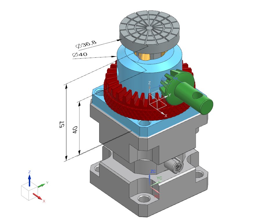
Mechanical Analysis
Tolerance Analysis
Centering the optical workpiece relative to the CNC spindle was critical to achieving consistent depth of cut and accurate force measurements. Tolerance analysis targeted maintaining radial runout within ±10 microns. An electric indicator probe was first visually aligned with the spinning optic to roughly gauge concentricity. The probe was then placed against the workpiece at a 150-micron resolution, and manual adjustments were made to minimize variation. The probe resolution was increased for finer adjustment, and the procedure was repeated until deviation across a full rotation was minimized. This method successfully achieved the centering tolerance required between the workpiece, fixture, and load cell.
Fatigue Analysis
A fatigue analysis was performed on the 1/4-20 steel bolt securing the fixture to the load cell. The bolt was assembled with an approximate torque of 5 lb-ft (6.8 N·m), generating a preload of about 2,500 N. Assuming vibration loading conditions typical for CNC operations and a fatigue limit of 250 MPa for carbon steel, the bolt exhibited a safety factor against fatigue failure greater than 1.6. For the aluminum 6061-T6 threads, thread shear strength analysis confirmed that the applied preload was safely supported, with a safety factor greater than 2. Thread engagement exceeded 1.5 times the bolt diameter, minimizing risk of thread stripping.
Fastener Torque Calculation
Although the bolt was not torqued with a calibrated wrench, the applied torque (~5 lb-ft) was below the maximum allowable torque for a 1/4-20 steel bolt, regardless of the material grade, as even the low strength (Grade 2) maximum torque is ~6 lb-ft. This ensured that the bolt preload remained safely within yield limits. No evidence of bolt loosening, stripping, or fixture instability was observed during any testing, validating the integrity of the bolted connection.
Material Selection
Aluminum 6061-T6 was selected for all fixture components due to its favorable combination of high strength, machinability, and cost-effectiveness. The optic workpieces were made of ULE (Ultra-Low Expansion) glass for its excellent dimensional stability and minimal thermal expansion, which are essential in precision optical fabrication. Dymax OP-GEL-29 was selected as the bonding adhesive based on its UV-curable properties and recommendation from Mike Pomerantz. Its mechanical properties were readily available, allowing it to be accurately modeled during finite element analysis.
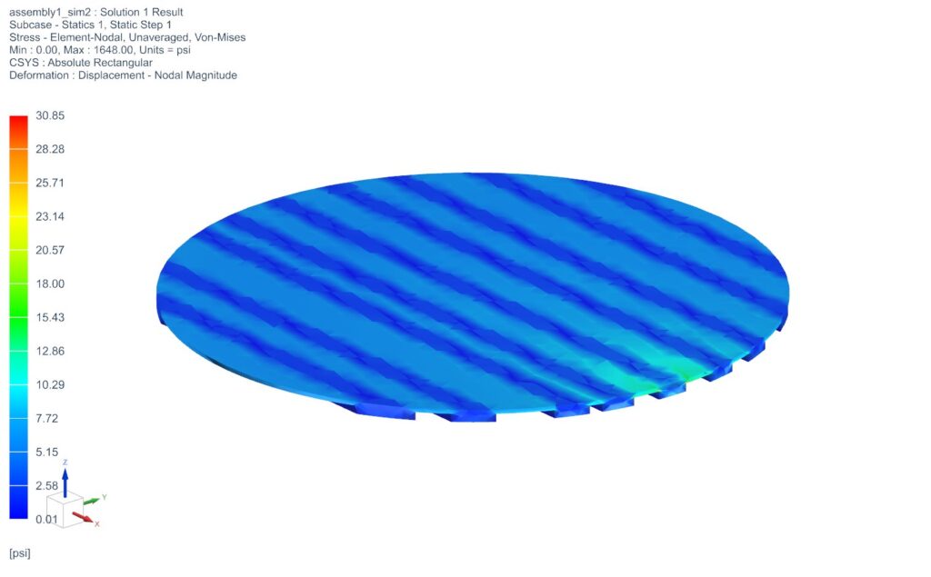
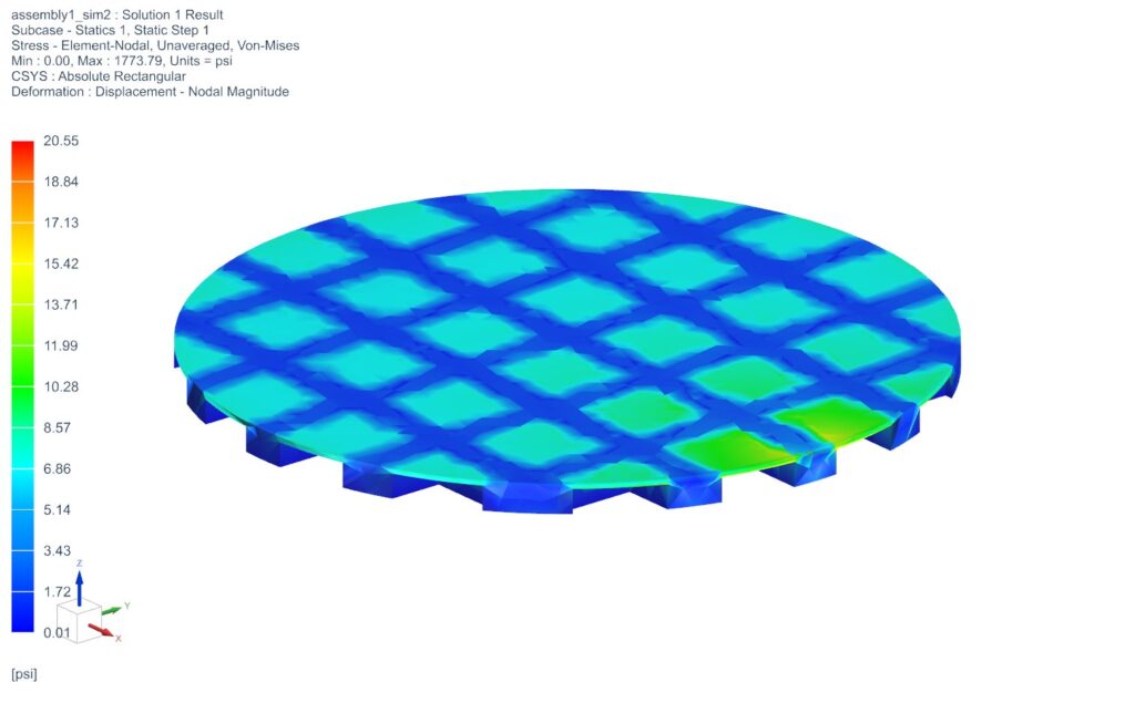
Computer-Based Analysis (FEA)
Finite Element Analysis (FEA) was conducted to simulate the geometry of the glue and it’s response under applied grinding loads. Tangential and normal loads of 20 N were applied at the optic edge. The optic was modeled as a 1.5-inch diameter, 0.25-inch thick ULE glass disc with fixed constraints below the glued region. Simulation results demonstrated that maximum induced stresses remained significantly below the yield strength of adhesive used (OP-29-GEL), ensuring structural safety under all loading scenarios.
These analyses confirmed that the fixture design, material selection, assembly method, and bonding approach would support reliable and accurate force measurement during CNC grinding operations without risk of structural failure.
Fundamental Mechanical Analysis
The necessary force from the screw to keep the glue plate from spinning with a 20lb load applied to the edge of the optic and a factor of safety of 2 is 7.2 lbs.
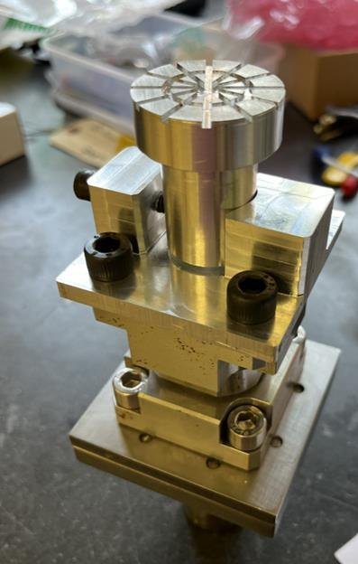
Manufacturing
In the project, two main pieces had to be manufactured. Both were machined from aluminum 6061. We chose to machine out of metal as opposed to 3D printing because of the tight tolerances we were trying to hit, as well as consistency in how the structure would respond to an applied load. Aluminum 6061 was chosen because of its low price point, availability, and ease of machining. The final assembly drawing and fabricated results are referenced in the appendix.
One piece to be manufactured was the base plate. The base plate was made from a piece of 2.5×2.5×2.5 in piece of stock. This piece of stock was machined using the HAAS CNC mill, and holes were added using the traditional mill.
The other piece was the glue plate. Five glue plates were made from a 12 inch long 1.5 inch diameter piece of round stock. The outer diameters were made on the lathe, and the pattern on the face was created with the HAAS CNC mill. A modification needed was adding a flat spot to locate the plates rotationally which was added using a traditional mill.
The CNC machine was utilized to create specific, complex geometries quickly for the glue plate faces. Otherwise, the parts were designed to be easily manufactured with the skills of the team in the machine shop.
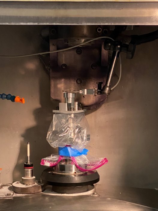
Another element of manufacturing in the project was mounting the workpieces to the glue plates. This was done using Dymax OP-29-Gel, a UV cure glue enabling us to quickly cure and detach glass from the glue plates (c). The glass was centered to the axis of rotation of the spindle of the Optipro machine to within 10 microns using a dial indicator. This was so we would have consistent depth of cut during testing.
| Estimate of Build Costs | |
| Purchased Hardware | $260.70 |
| Manufacturing | $2100 |
| Gluing | $1800 |
| Total | $4160.70 |
| Estimate of Development Time | |
| Eric Bang | 15 hours |
| Jules Esen | 15 hours |
| Jonathan Friedman | 15 hours |
| Total | 45 hours |
If the system were to be scaled to 1000 systems, it would be beneficial to create a simplified glue face that could be machined on a CNC lathe. This way the entire glue plate could be created in a single CNC run saving a lot of time. Also being able to consistently center parts using a datum structure of the fixture as opposed to measuring the runout while it is in the Optipro would allow the gluing of optics outside of the machining lab. The blocking of optics would be much more efficient.
Test Plan and Results
All requirements and specifications were met during testing for edging for the reported results. There were issues meeting the first specification of measuring forces in 3 DOF for all of the given workpieces. The z-component started producing unreliable results tested during calibration. One theory is moisture buildup in the z-port of the load cell inside the protective shower curtain. By blowing pressurized air, more reliable z data was taken, however, did not remain consistent in accuracy for other runs. It is important to note that the edging cuts are made in the x and y directions, not the z. Therefore, there are still valuable results measured.
The testing objective is to explore the relationship between the measured axial loads and depth of cut experienced on the optic for CNC edging processes.
The preliminary setup included 5 workpieces glued on their respective glue plates, power supply connections, base plate fastened to the load cell, mass for calibration, and data collection programs open.
Before an experiment is tested with a new glue plate, calibration must be done. During testing, forces will be analyzed at low and high frequencies during CNC edging. Measuring at low frequencies provides a big picture on the force variation at all three channels, measuring 30 force data points per second. The high frequency testing observes a detailed outlook of the forces at each rotation of the tool, one channel at a time at 200 data points per second. In the program provided for data collection, it will produce results for both high and low frequency data collection.
Forces will be analyzed in the following depth of cut order on each workpiece:
- Precut: .0075”
- Small: .0075”
- Medium: .015”
- Deep: .0225”
- Repeat steps 2-4
All cuts have the same spindle speed set to 4400 RPM and feed rate to 6 IPM.
The following are the best results of the resultant forces vs depths of cut for three workpieces [19]. For the shallow cuts of workpieces 11 & 13 and the deep cut for workpiece 13 there is no data due to difficulties with the tool path giving inconsistent cuts.
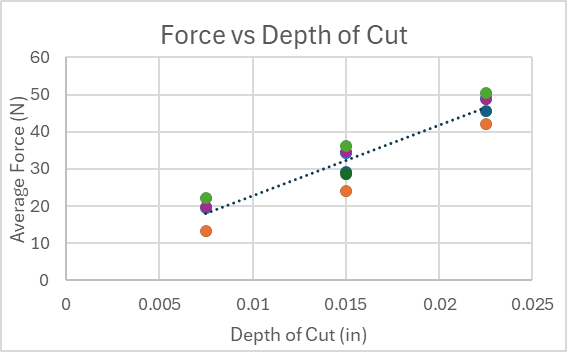
Increasing depths of cut shows a strong linear correlation to an increase of force.
It should also be noted that although the feed rate was calculated to be 6 inches per minute, the feed rate was set by rotating the workpiece. The speed of rotation was calculated using a 1.5 inch diameter, but as we ran through trials that diameter shrunk. This effectively raised the feed rate as we took more samples from the same workpiece. This could be one explanation for the variation in average force for each depth of cut. The colors of the plot correspond to an individual round of testing, and the tests taken on smaller diameter optics show higher forces.
Each depth of cut was tested across 6 independent trials to assess repeatability. The resulting force measurements showed minimal variation between trials, indicating consistency. The following statistics were calculated: the mean average, force increased proportionally with the depth of cut and the standard deviation across repeated trials remained low. Due to time constraints and machine availability, the same workpiece was limited to three trials per experiment. A more robust statistical study would involve more trials per condition to allow for stronger confidence intervals and better quantification of variability. For the best quality control, following the Six Sigma is ideal.
A limitation of the current setup is that environmental variables such as temperature or machine wear over time were not systematically varied. Future tests could include trials across different machine conditions to verify robustness. The system did not require active tuning of hardware parameters during testing, however prior to testing the glue plate was altered to allow for additional clearance between the outer edge of the workpiece and the glue plate.
Operational parameters such as CNC tool speed, feed rate, and depth of cut could influence force behavior. To further understand the effects, a high frequency study was performed.
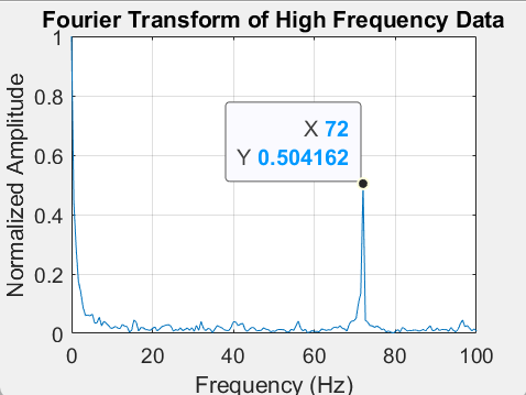
The peak represents when the tool made contact with the workpiece at 72 Hz. The theoretical contact frequency based on spindle speed 4400 RPM is 73.33 Hz, and this small difference could be explained by an actual sampling rate slightly below the nominal 200Hz. There are also no other large frequencies present (besides the low frequency of the optic rotating at 1 rotation per 47 seconds).
To further optimize our process consistency, our simple design of experiments (DOE) could be performed where spindle speed and feed rate are varied, the response variable is a resultant force xy, and the goal is to identify conditions that minimize load fluctuations while maintaining a desired material removal rate. This DOE would help fine-tune the CNC parameters for better consistency and potentially lower cutting forces.
Intellectual Property
The design and process are likely not patentable. The technology and methods we used are not novel. Many fixtures similar to ours have been created with much more detail. One such fixture is patent US8905388B2, which describes a block piece for holding an optical workpiece (b). Our technology and methods would also not qualify as non-obvious, as we used very standard methods to conduct our experiments.
One classification that our device might fall under is B23Q3/105 – Auxiliary supporting devices independent of the machine tool (c). Here there are many different methods of holding blanks for manufacturing as well as modular designs similar to ours. The top assignees in the field are 重庆富吉机械制造有限公司, 宁夏际华环境安全科技有限公司, and Sax Gmbh, with the top inventors being 贺开义, 宜孝 藤村, and 张晓磊.
Societal and Environmental Implications
The intent of this project is to support CNC fabrication of lightweight optics for aerospace applications. Possible ethical issues include technology support for defense customers and the lack of knowledge on how the optics will be used. Other concerns regarding the environment include aluminum material waste from fabricating glue plates. Five glue plates were machined to help save on testing time. One solution can include reducing the number of glue plates by developing a faster method of bonding the workpiece concentrically to the spindle’s datum with a dial indicator. A removable jig/collar can be designed to have the same mechanical axis of orientation as the spindle. This would eliminate the time needed to tap the workpiece into place using the dial indicator.
Recommendations for Future Work
If given additional time to work on the project, the main priority would be to collect a larger and more diverse set of load data across additional tool paths. This would help confirm the repeatability of the results and ensure that the tool paths are providing consistent depths of cut across different operations. With more time, the project could also expand to include testing different optical materials beyond the current baseline, which would allow a better understanding of how material properties influence grinding forces. Additionally, investigating the effects of different tool grits and alternative grinding operations would provide broader insight into the full range of CNC optical fabrication conditions. The collected data and scope of the project is well-outlined and can only be extrapolated to a certain degree, especially in a field where precision plays such a significant role. The fixture itself currently performs exactly as needed for the scope of the project, providing reliable mounting, force measurement, and compatibility with the Opti-Pro SX50. Any further redesign or development of the mounting fixture would likely be outside the intended goals of this project and unnecessary unless the project scope were expanded outside of data collection and analysis and focused on aspects such as production-level manufacturing.
Project Presentation Video
Final Design Review Paper