Team Members:
[picture of team]Amanda Lee, Elizabeth Martin, Leslii Silveus, Ava Staub
Abstract
The objective of this project was to create a scanning apparatus that will improve the scanning process of the iQ3 Butterfly Ultrasound Probe (Figure 3.) for use with damaged finger tendons. This project was sponsored by the URMC Health Lab which had a prototype of this project already started. Based off the feedback from the prototype, a new design of the apparatus was created and used for the semester. After multiple iterations on various parts of the device, a prototype was put together to start testing with. The scanning mechanism has both a manual and automated part so the scanning can be done with a person controlling the movement of the probe or autonomously with the probe moving based on feedback from a laser sensor. All the programing was done using Arduinos and the Arduino IDE software. NX was used for all the CAD and analysis along with exporting components to be 3D printed. To test the code, a 3D printed hand was placed underneath the apparatus to make sure everything moved as expected. Once a water bath was constructed, it was placed underneath and testing could be done on actual finger tendons. Most of the requirements and specifications were met and it was decided that some aspects would be pushed back to the Health Lab to complete, such as the image processing components.

Problem Definition
Ultrasound imaging is critical in diagnostics but is limited by two key challenges: it requires specialized expertise to operate and analyze, and traditional handheld probes are restricted to 2D imaging. In clinical settings for tendon repair therapy, there is no fully automated scanning system that can cohesively and accurately scan a damaged hand tendon, obtain 3D ultrasound images, calculate the scar tissue volume, and predict the functionality of the patient’s tendon. Thus, our goal for this project is to develop a mechanical device that performs ultrasound scans using handheld probes, while safely preventing contact with the patient’s injured hand, overall improving image quality, diagnostic accuracy, and patient comfort.
Table 1: Deliverables
| Deliverables | |
| 1. | Prototype mount compatible with phone and butterfly probe |
| 2. | Prototype water tank for patient’s arm/hand |
| 3. | Prototype scanning device |
| 4. | Prototype software to support prototypes movement |
| 5. | Prototype software for image processing |
| 6. | Complete CAD and bill of materials |
| 7. | Design report to include in testing |
Table 2: Requirements
| Requirements | Description | Pass/Fail |
| 1. | The prototype mount can hold the probe and iPhone securely in a position where the probe can scan. | Failed – can hold securely but there is still some displacement in the z-direction |
| 2. | The prototype scanning device can move in x and z directions and rotate about y axis. | Passed |
| 3. | The patient must be able to put their hand in the water bath comfortably. | Passed |
| 4. | The probe and iPhone should be easily inserted and removed. | Passed |
| 5. | The prototype program can piece together images from frames taken from butterfly probe. | Failed – Health Lab took over image processing |
| 6. | The transversal mechanism must disengage if met with resistance (safety). | Passed |
Table 3: Specifications
| Specifications | Description | Method of Evaluation | Pass/Fail |
| 1. | Apparatus shouldn’t take up an area greater than 2ft^2 | Measure length/width with ruler | Passed |
| 2. | Mount can withstand 5 lbf (force of putting in the butterfly and the weight of butterfly and phone resting on mount) | The force will be evaluated using NX finite element analysis. | Passed |
| 3. | The Butterfly probe should be able to rotate ±10 degrees about the y-axis | The angle will be measured using a protractor. | Passed |
| 4. | The Butterfly probe can move at least 6 inches from starting position in the x and z | The Butterfly probe can move at least 6 inches from starting position in the x and z | Passed |
| 5. | The Butterfly probe can be moved in the x and z direction with a position accuracy of +/- 0.04 in. | The position accuracy will be measured using a scale or calipers | Passed |
| 6. | The Butterfly probe can be angled around the y axis with an accuracy of +/- 1 degree | The angle accuracy will be measured using an angle finder. | Passed |
| 7. | The maximum scan time of the tendon should be less than 60 seconds. | The scan time will be measured with a timer. | Passed |
Concept Selection
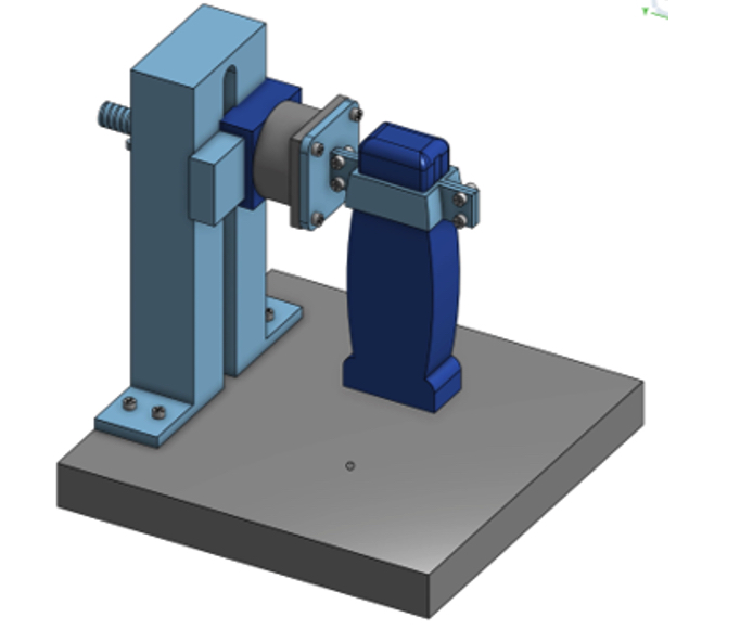

The baseline is a prototype by Dr. Ketonis and Dr. Loiselle, shown in Figure 4, where the probe is moved in only the x direction by a rack and pinion system. Figure 5 shows the baseline design compared to the top concepts of the frame for the apparatus. Concept 2 differs from the baseline where the x motion is driven from the bottom and two posts move on the track. Concept 3 has four posts with slanted crossbars that provide the x motion and a separate carriage provides the z motion. Concept 4 is similar to Concept 3; however, the top bars are not slanted and are horizontal and still has the z motion provided by a separate carriage.
Concept 4 was chosen for the movement selection because while the second and third designs have the structure to prevent displacement in the z-direction that the baseline design exhibits, the last design scored the highest in terms of ease of build/assembly.
Final Design
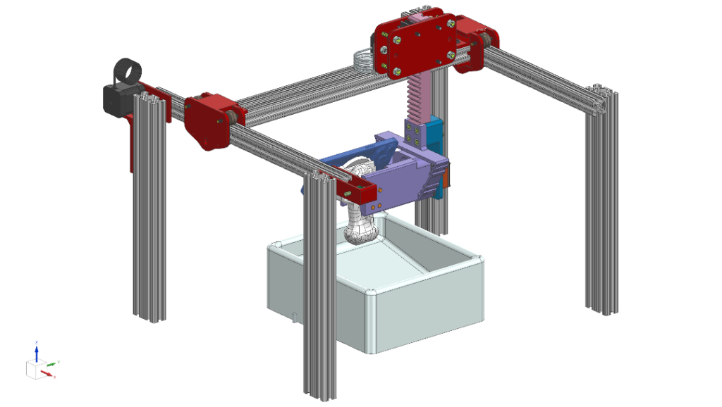
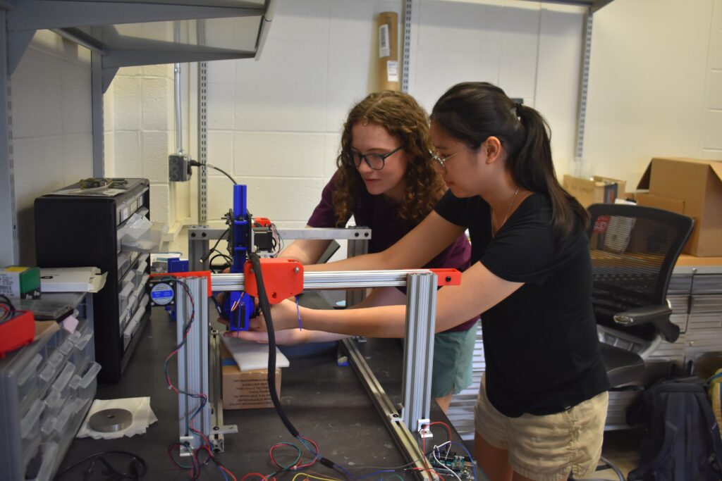
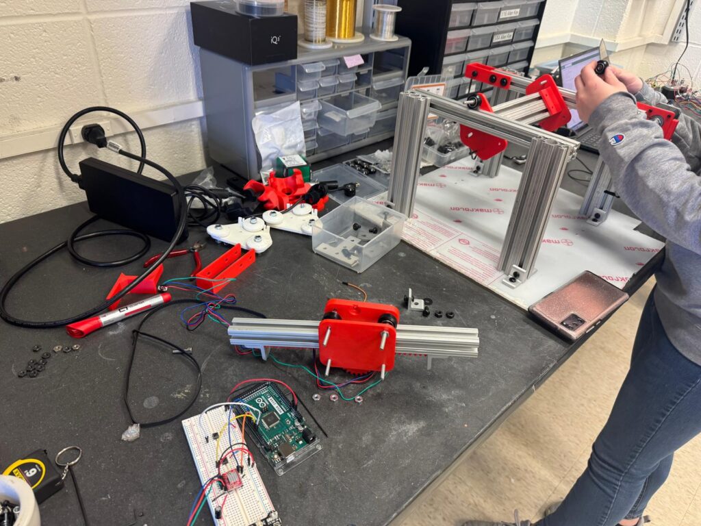
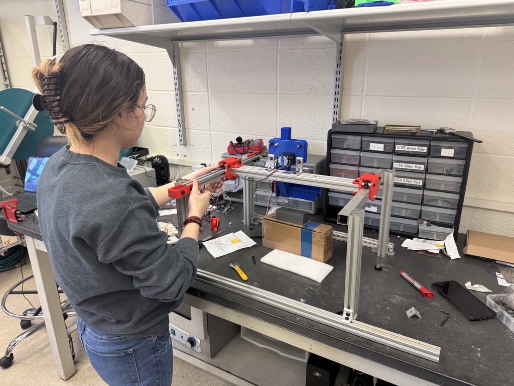
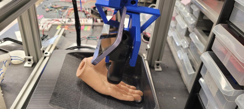
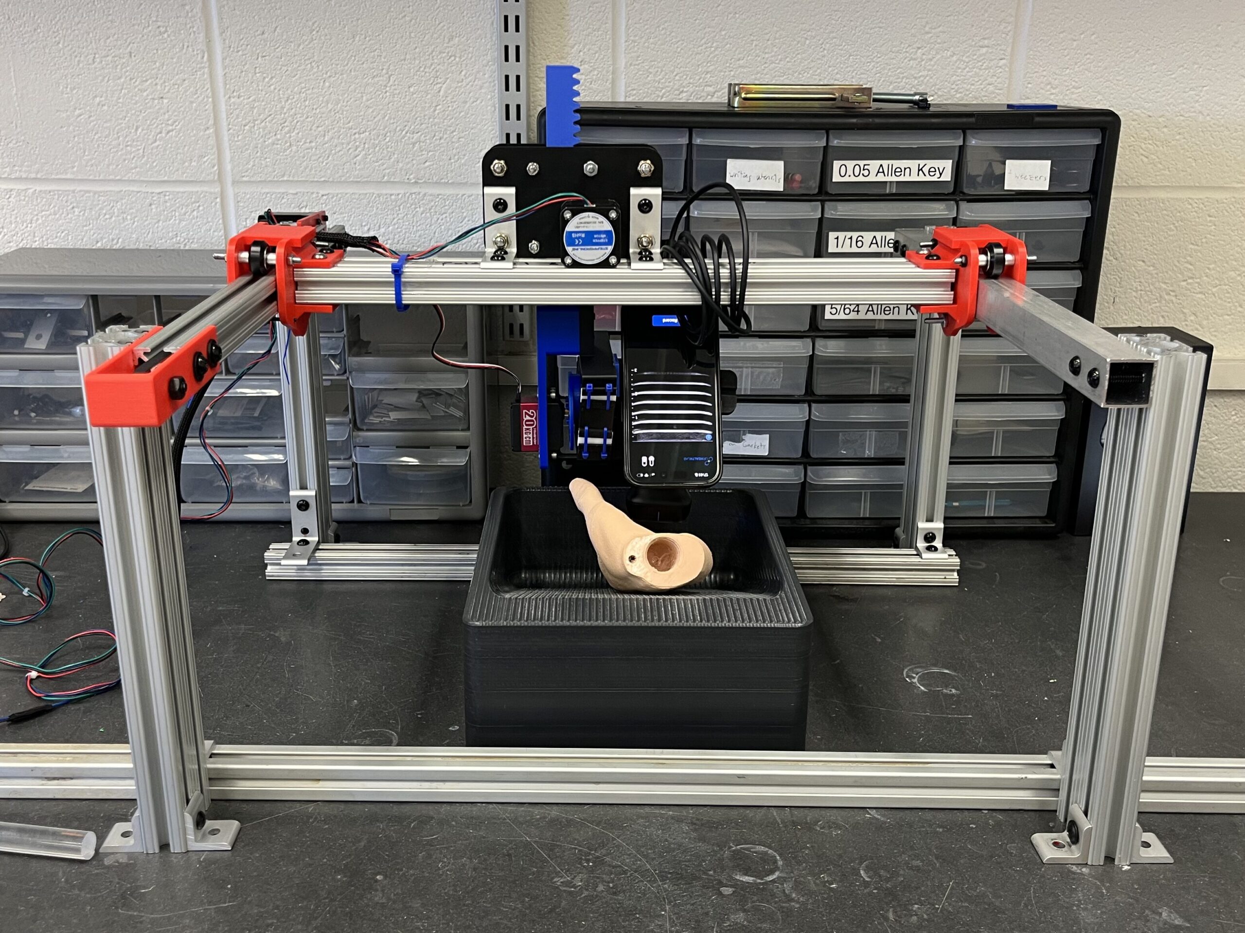
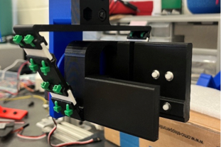
The final concept, shown in Figure 6, consists of three motion systems integrated together to assist the scan. The back-and-forth motion, defined by the x-axis is driven by a belt and stepper motor. This carries the cross-bar holding the z sub-assembly, flexure, probe, and phone. A rack and pinion with a stepper motor moves the flexure, probe, and phone up and down in the z-direction. A servo cam that drives the flexure device is used to rotate the probe and phone about the y-axis in a sweep like motion. The flexure, shown in Figure 7, uses TPU joints to enhance the flexure’s rotation range and spring plungers to securely hold the probe in place. A time-of-flight distance sensor is used to automate the z-motion as a safety feature. Once the tip of the probe gets within 20-30 mm of the finger, the z-motion reverses direction to move away from the finger.
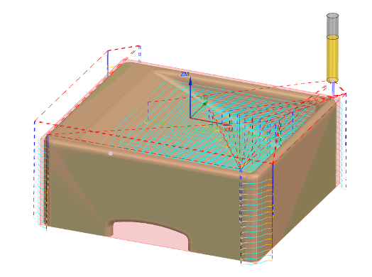
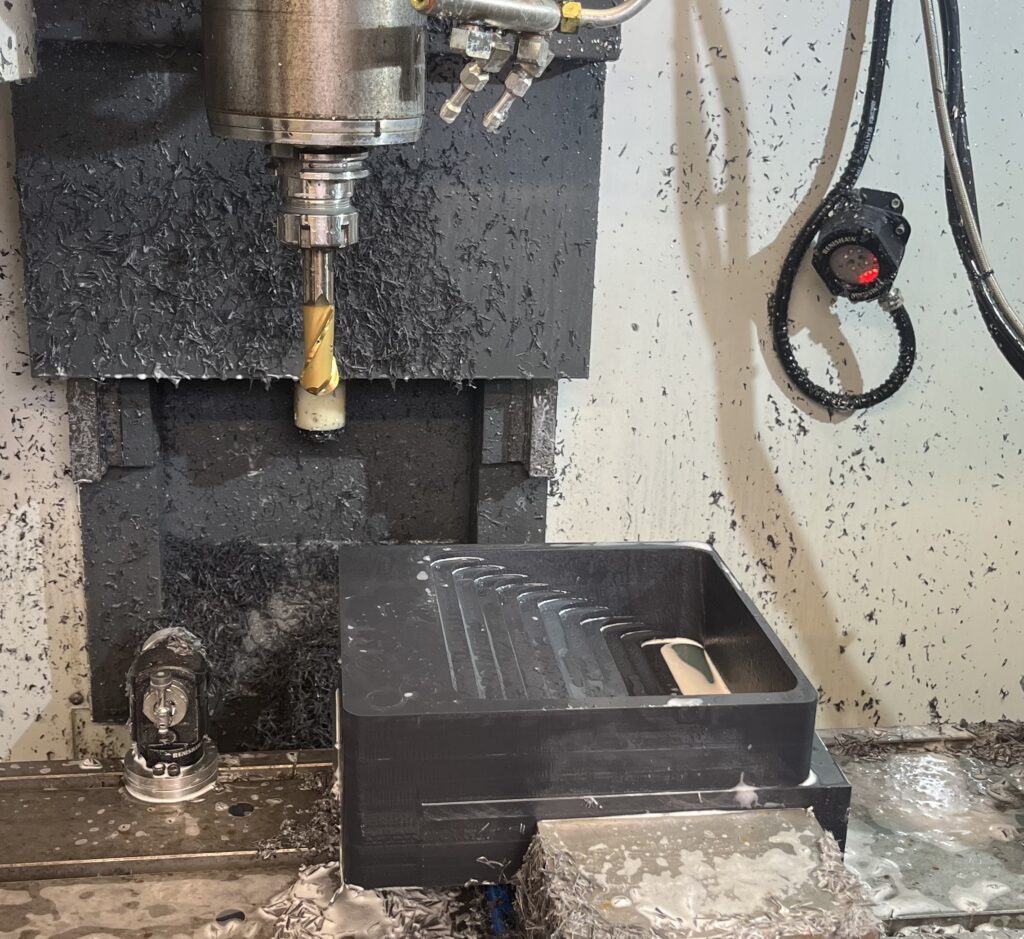
All primary components of the design except for the frame and the water bath were 3D printed due to the quick iteration time that was needed. The frame of the system is made from Aluminum 80/20 bars to allow for adjustments in positions and to use tracks for the x-motion of the system. The water bath that the hand rests in was made from sheets of PVC that were solvent weld together and then the inside ramp was created by CNC machining out the inside. The tool path used to create the bath is shown in Figure 8, along with the physical part while it was being machined in the HAAS Mill.
Final Design Report
To review a full pdf of our Final Design Report, see the link below.
Video Presentation
[Add video here]Pictures