Hello! We are the PlanOpSim InverseMeta team. We have been working with our primary customer contact, Lieven Penninck at PlanOpSim, and our faculty advisor Professor Michele Cotrufo. Our senior design project focuses on designing metasurfaces, which are nanostructured optical devices that can precisely control light at the sub-wavelength scale.
Team Members
| Nancy Mabry | Linrui (Stephen) Tan | Depei Tong |
|---|---|---|
 |  |  |
| nmabry@u.rochester.edu | ltan13@u.rochester.edu | dtong@u.rochester.edu |
| Project Coordinator & Document Handler | Scribe | Customer Liasion |
Customer
Lieven Penninck, PhD
CEO, Co-Founder
PlanOpSim
lieven.penninck@planopsim.com
Faculty Advisor
Michele Cotrufo, PhD
Assistant Professor of Optics
University of Rochester
michele.cotrufo@rochester.edu
Vision
Our project concentrates on using PlanOpSim’s optimization algorithm software to enhance the efficiency and functionality of nanostructured optical devices. Unlike traditional engineering methods, in which a structure is designed and then tested, inverse design begins with a target optical response and uses computational methods to determine the optimal nanostructure to achieve that function. For our first objective, we designed a metasurface capable of displaying two distinct holographic images depending on whether the incident light is in the TE or TM polarization state. For the second, we aimed to design a metasurface that produces specific colors by controlling the interaction of light with carefully engineered nanostructures.
We utilized inverse design to achieve the desired results for both the polarization-switching hologram and the structural color designs. In the world of metalenses, inverse design is a computational method by which to achieve a desired optical response. These mathematical algorithms are performed through PlanOpSim’s own software. Compared to traditional design methods, inverse design automates much of the design process and therefore reduces design time. On the other hand, inverse design may produce intricate, asymmetrical structures that are optimized for performance specifications but are not easily fabricated. Thus, human intuition, knowledge, and experience are still vital during the design process.


Polarization-Switching Hologram
Project Scope
This task focuses on the design and simulation of a metasurface that outputs different holographic images depending on the polarization of the incident light. Using PlanOpSim’s software, we targeted two distinct holographic outputs: the PlanOpSim logo for TE polarization and the letter “R” for TM polarization. To accomplish this, we constructed a library composed of meta cell structures with varying structures and dimensions, each providing high transmission and full 2π (-180º to 180º) phase coverage for both polarization states.

The meta cell library was used alongside PlanOpSim’s design algorithms to generate the final metasurface design. By tailoring the phase response of each meta cell to the TE and TM polarizations, the metasurface effectively redirects light into different diffraction patterns, enabling the dynamic switching between the two target images. We took into consideration the near-field wavefront efficiency (NFWF)/transmission efficiency as well as the far-field wavefront efficiency (FFWF)/Fraunhofer efficiency to ensure that the holographic images produced were discernible. This task highlights the power of polarization-dependent metasurface design for compact and reconfigurable optical devices.
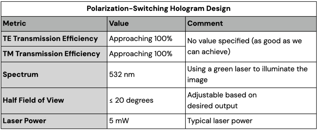
Design Specifications
Results
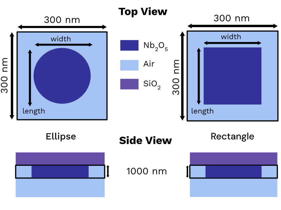
The below simulation results were generated using elliptical and rectangular meta cell structures of Nb2O5 (niobium pentoxide) with a thickness of 1000 nm (1 μm) and a meta cell size of 300 nm by 300 nm. The incident (SiO2) and exit (air) layers have infinite thickness. The lengths and widths for both structures were varied from 5 nm to 230 nm in steps of 10 nm in the software. Below is a diagram of the meta cell structures with labeled dimensions and materials.
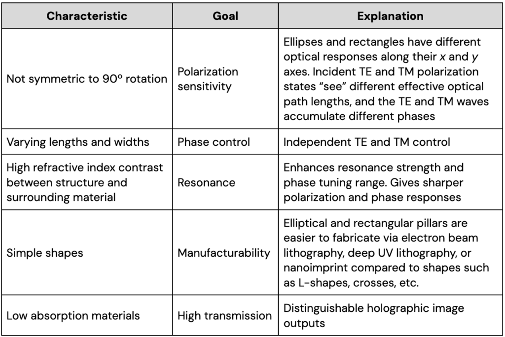
The table below outlines what we were aiming for when designing the meta cell structures for the polarization-switching hologram metasurface. These include material, shape, thickness, and geometries of the structures.
Below are transmission amplitude and phase plot simulations for the elliptical and rectangular meta cell structures. Each plot is a map with x axis as length, y axis as width, and a color bar displaying either transmission amplitude or phase, as labeled. Every possible geometry of the meta cell structure within the 5-230 nm parameter is simulated for transmission amplitude and phase so that we can select which geometries to use for the metasurface design. In these plots we are looking for high transmission amplitude (dark red) and full 2π phase coverage (blue to red) to be able to achieve the polarization-switching holograms with our metasurface.
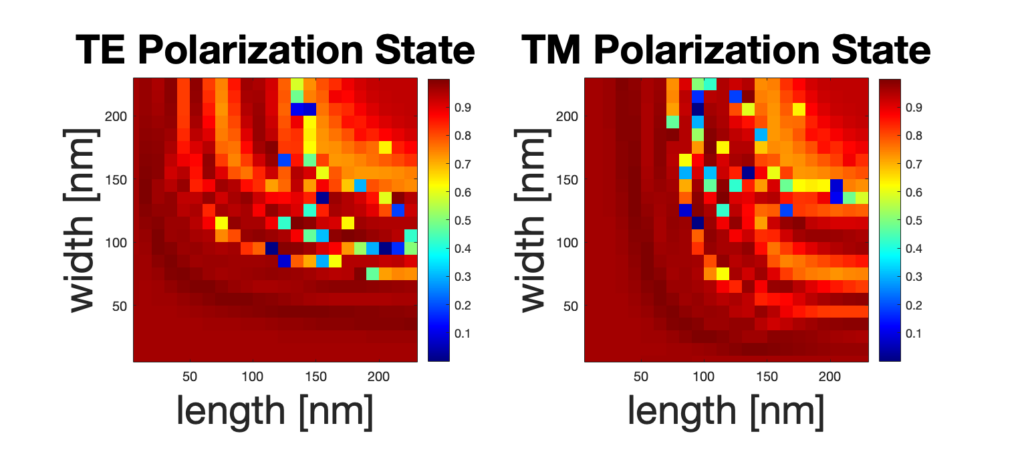
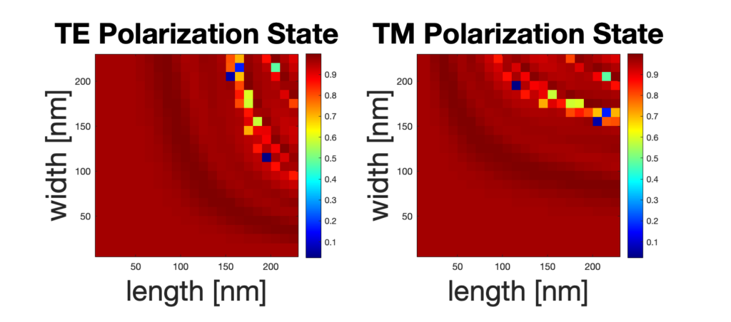
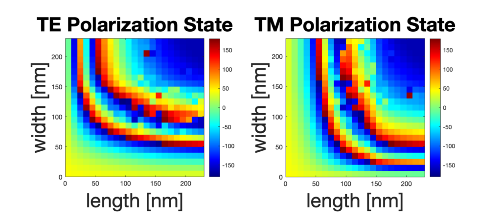
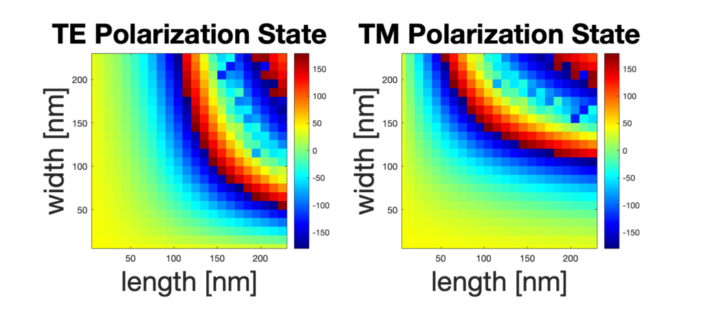
The above meta cell structures were able to achieve consistently high transmission amplitudes across the different geometries as well as cover a full 2π phase range. A metasurface needs high transmission across the meta cells in order to have an even intensity pattern. Also, the metasurface modulates the phase of the incoming light to shape the wavefront into the desired holographic image. After creating the meta cell library with the above described meta cell structures, we were able to generate a metasurface of 300 µm by 300 µm.
The following figures are the design targets used for the polarization-switching hologram metasurface design. The left is the original target with a color bar displaying amplitude (0 to 1), while the right is the simulated result from our metasurface design with a color bar displaying intensity in W/m2.


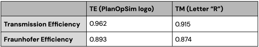
The following table contains the near-field wavefront/transmission and far-field/Fraunhofer efficiencies for our final polarization-switching hologram metasurface design:
Structural Color
Project Scope
This task focuses on designing a metasurface that creates color through its physical structure, rather than through pigments or dyes. By careful structure design and arrangement of meta cells, we can control the way in which light interacts with the surface. When white light hits the surface, certain colors are reflected more strongly than others, therefore making the surface appear a certain color to the human eye.
Using PlanOpSim simulation software, we conducted systematic parameter sweeps to optimize the metasurface design for maximum reflectivity at the target wavelength. The design was refined through simulated transmission analysis, ensuring that the structure meets the desired optical performance. This design offers an environmentally friendly alternative to traditional coloration techniques and enables precise color control at the nanoscale.
Design Specifications
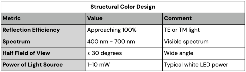
The structural color metasurface design uses a white LED (1-10 mW) as its light source in the visible light spectrum. Our goal is to achieve as high a reflection efficiency as possible for any incident polarization state.
Results
Structural colors arise from the interaction of light with nanostructures, rather than from chemical pigments or dyes. These colors are produced through mechanisms such as interference, diffraction, scattering, and resonance. Many vibrant colors in nature, such as in butterfly wings and peacock feathers, are structural colors. Metasurfaces can be used to generate artificial structural colors. We are able to tune these colors by adjusting the structure geometries, material, and incident light.
For structural color to be achieved, the transmission or reflection of different wavelengths must vary in intensity, creating selective enhancement or suppression of certain colors. The combination of these wavelength-dependent interactions produces the observed structural color. Essentially, we are focusing on achieving a spectral response to produce a certain color coordinate.
Note: This part of our senior design project does not have a final design or final results due to time constraints. We discussed the intermediate designs we were able to produce in the timeframe with our customer and they are satisfied with the progress we have made.
Our current design involves an elliptical meta-cell structure and a rectangular meta cell structure with varying parameters. The x radius and y radius of the elliptical pillars vary from 50-110 nm in steps of 5 nm, and the length and width of the rectangular meta cell structures vary from 50-220 nm in steps of 10 nm. This design is diagrammed in the figures below, where both a top view and a side view of the layers of the unit meta cells can be seen.

For this design, we focus on reflection rather than transmission, as in the polarization-switching hologram metasurface design. More specifically, we want to achieve meta cells with particular geometries such that resonance occurs and the meta cell reflects light at maximum efficiency. Each meta cell can be designed to resonate at a particular wavelength, thereby outputting the structural color. Also, the periodicity (spacing between meta cells) affects how the individual meta cells interact with each other through interference. When the incident light interacts with the metasurface, the reflected light from different meta cells can either destructively or constructively interfere with one another, causing a decrease or an increase in efficiency, respectively.
The air surrounding the Nb2O5 (niobium pentoxide) structure acts as a spacer and allows for the design of structured metasurfaces with high optical contrast between materials. The low refractive index of air ensures that light travels efficiently between the meta cells, allowing for precise control of reflection and transmission through interference and resonance effects. The structure of Nb2O5 surrounded by air enables constructive interference for specific wavelengths of light, maximizing reflection at the desired colors. The air layers ensure that the light interacts primarily with the Nb2O5 meta cell structure, which controls the light’s reflection properties based on its geometry and material properties.
The metasurface design uses the elliptical and rectangular meta cell structures as seen above. The plots in the following figures demonstrate the simulated results for the metasurface design. We are aiming to generate each letter as a different wavelength/color.
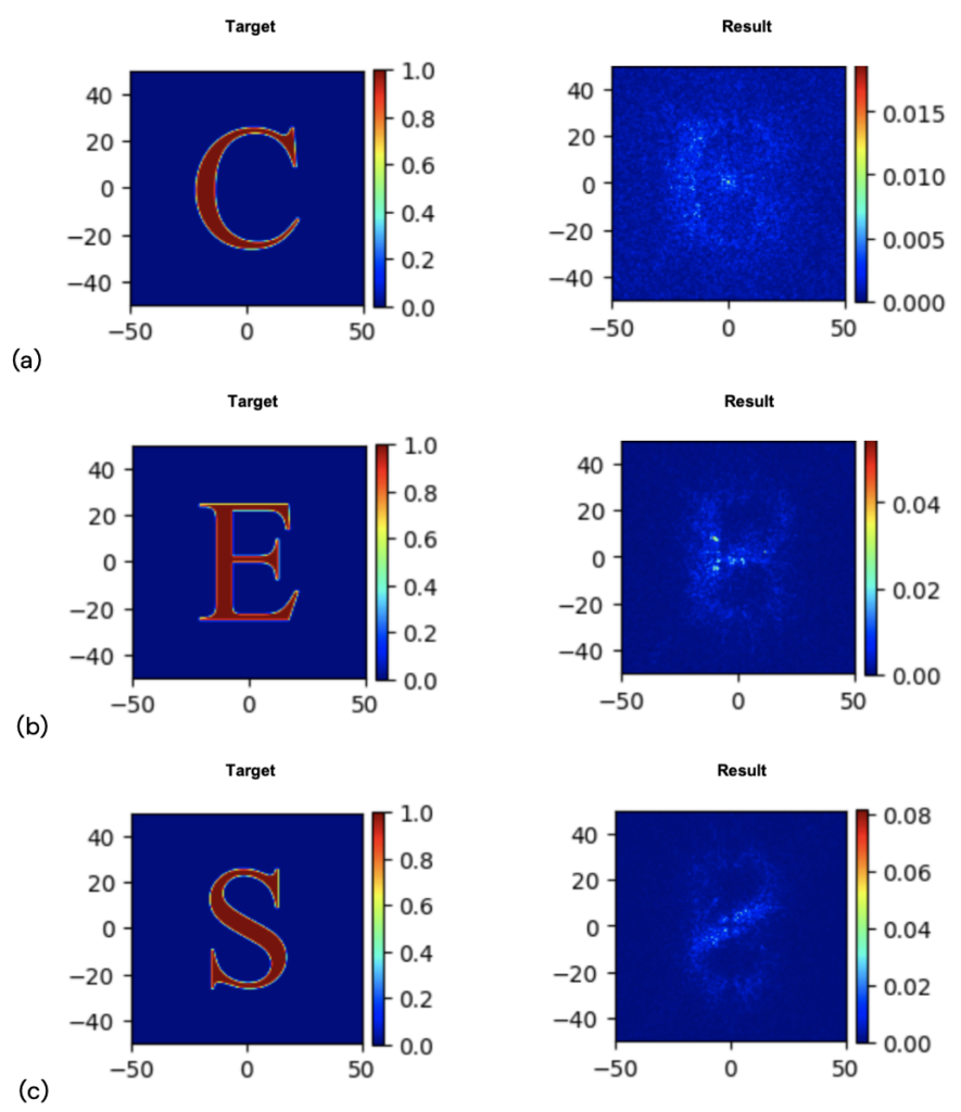
We are able to achieve 3% reflection from 475 – 575 nm. As seen in the plots above, the letters are not discernible, meaning we have not yet achieved our goal of generating high reflection values to output a specific structural color.
Due to time constraints, we were unable to complete a final metasurface design for the structural color project. We made sufficient progress on our designs, and our customer was satisfied with the preliminary results we were able to produce.
Conclusion
Polarization-Switching Hologram Design
Our metasurface design has a high Fraunhofer transmission efficiency, and the output holographic images are certainly discernible; however, further improvements can be made in the manufacturability of the meta-cell structures. More specifically, some of the meta cell structures are very narrow and are not able to be fabricated. More restriction of the length and width parameters for both the elliptical and rectangular meta cell structures must be implemented.
Structural Color Design
We have designed individual meta cell structures that can be used to create a metasurface for the production of structural colors, but more variables are needed for the system, and longer simulation times are required to reinforce that the spectrum is able to be reproduced. Further improvements include tuning of meta cell structures to achieve a higher reflection efficiency.
Acknowledgements
Primary Customer Contact: Lieven Penninck
Secondary Customer Contact: Bavo Robben
Faculty Advisor: Prof. Michele Cotrufo
Senior Design Instructor: Prof. Wayne Knox
Thank you to Lieven, Bavo, Prof. Cotrufo, and Prof. Knox for all of their support, guidance, and encouragement throughout this project. We are truly grateful for you. Also, a special shoutout to the entire Optics and Optical Engineering class of 2025 for their dedication and hard work the past four years!
References
PlanOpSim software, https://app.planopsim.com.
Nanoimprint Lithography (NIL) Foundry, moxtek.com/wp-content/uploads/OPT-DATA-1012-NanoImprint-NIL-Datasheet.pdf. Accessed 9 Dec. 2024.
Qi-Tong Li, et.al, “Polarization-independent and high-efficiency dielectric metasurfaces for visible light,” Opt. Express 24, 16309-16319 (2016).