Team Members
Supervisors
Dr. Amy Lerner, Dr. Greg Gdowski, Mr. Martin Gira
Customers
Emmanuel N. Menga, M.D. Orthopedic Surgery, SMH
Abstract
For spinal surgeons who face difficulty visualizing the nerve root during spinal decompressions, the Meramec suction/elevator is a surgical instrument that combines multiple instrument functions to free surgeons’ hands and increase OR efficiency. It combines the functionality and familiarity of existing suction tips and manual elevators with end effector geometry specific to the lumbar nerve roots, reducing the need to switch instruments. This improves OR workflow and increases patient safety.
Problem to be addressed
Clinical Scenario
During spinal decompression surgery, the goal is to remove bone and other tissue that is putting pressure on the nerve roots (spinal stenosis). The surgeon uses three main tools; a cutting instrument to remove the bone causing pressure on the nerve roots, an elevator to protect the nerve roots from being cut, and a suction tube to suction the pooling fluids, allowing the surgeon to see what he is doing. All three instruments need to be used simultaneously, but this cannot be done because the surgeon only has two hands. Therefore, the surgeon is forced to switch between the three instruments, wasting time and money in the operating room. Based on time studies done in the operating room, the surgeon switches instruments every 45 seconds for a duration of the decompression. At an average cost of $37 per minute of operating room time, it is estimated that $150 million is wasted annually on this simple efficiency issue.
Customer Needs
To address this issue, the surgeon requires a way to simultaneously elevate and visualize the nerve root. Our design achieves this by combining the elevator and suction tip into a single instrument. This allows the surgeon to cut away bone with one hand and elevate/suction with the other hand. This eliminates the need to switch instruments. Based on voice-of-customer interviews with orthopedic and neurosurgeons, as well as supporting OR staff such as scrub nurses and circulating nurses, the device should have the following attributes.
- Is compatible with existing suction machines and associated tubing.
- Allows an additional cutting tool to simultaneously be placed in the foraminal space.
- Retracts the nerve root without damaging it.
- Suctions fluid in the immediate area.
Our design and analysis
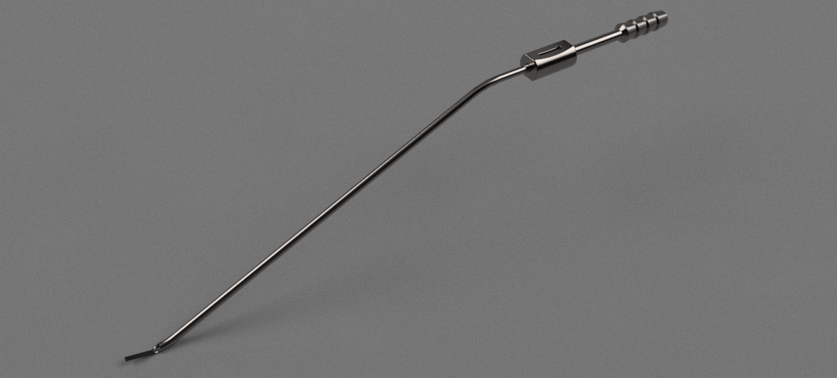
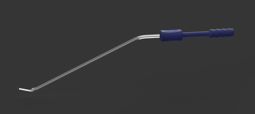
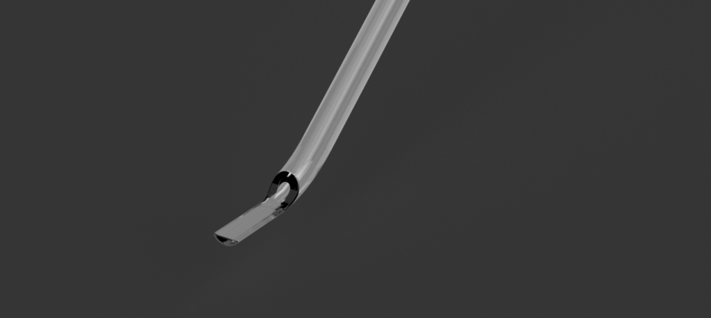
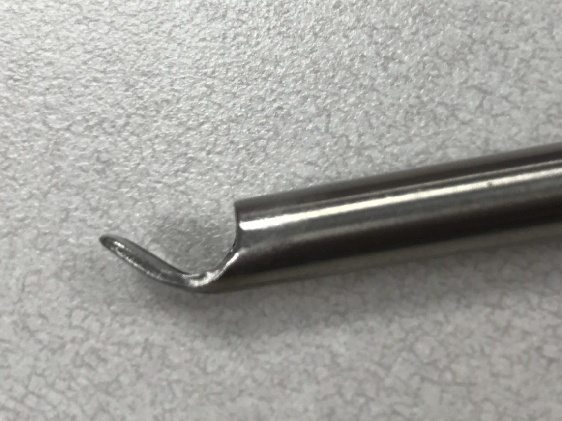
Our device is largely based off existing suction tips with suction control. The proximal, barbed end attaches to a suction hose, which routes to a stationary suction machine in the operating room. Distal to this is the thumb control, which consists of an opening to the main cannulation of the instrument. By covering the hole in varying degrees, the user can control how much suction pressure is at the tip of the device. At the distal tip, there is an elevator paddle that extends past the suction opening. This paddle allows the user to manipulate fine structures while simultaneously suctioning fluid in the immediate area.
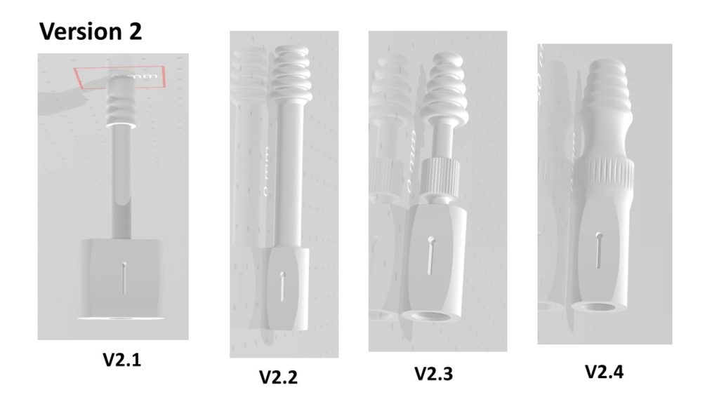
Different device components saw independent prototype iteration. The handle containing the thumb control and barb was the focus of much attention because it was responsible for the connection to existing suction tubes, suction control, and comfortable operation. The figure above shows the iterations of the handle on prototype version 2. Performance in suction tests, structural stability, and ergonomics informed progression from one design to the next.
Engineering Analyses
To translate our customer needs into measurable, testable metrics, Product Requirement Specifications were created and our design was evaluated against these specs. Three main areas of concern were tested – the structural integrity of the device, the fluid flow rate that the device allowed, and how the device physically fit in the context of the surgery.
Deformation Analysis – FEA Model
Finite element analyses (FEA) were done on models of existing instruments, as well as our instrument. The results from existing instruments were compared to those from our device to see if our device performed comparably to predicate instruments.
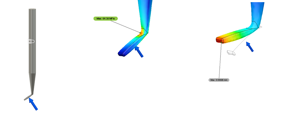
The FEA analysis was compared to real-life deformation tests with identical geometry to verify if the FEA-estimated deformation under a given load matched the observed performance of device prototypes. The FEA deformation matched the observed deformation within 10%.
Deformation Analysis – Prototype Evaluation
Once prototypes were developed, the deformation vs. load behavior was measured. This was compared to the predictions from the FEA model to see how accurate these predictions were. The loads for deformation (~1.65lbf) were also compared to the expected load in the context of the surgery (0.13-0.80lbf).
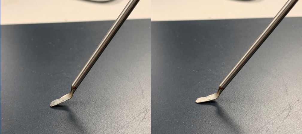
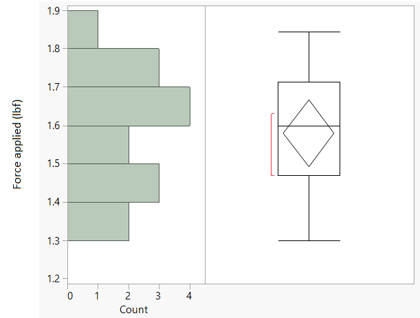
The figure above shows the results of a deformation test judged by visual inspection. Prototype 1 was loaded on a scale until deformation was achieved and the load on the scale was noted. Since the in-context expected load was a maximum of 0.80lbf, to allow for a factor of safety greater than 3, it was determined that the device should not deform under a load less than 2.4lbf. Therefore, prototype 1 did not meet the requirement. Prototype 2 used a thicker wall and allowed for a thicker elevator paddle. Prototype 2 was never tested, but its paddle thickness was roughly twice that of prototype 1.
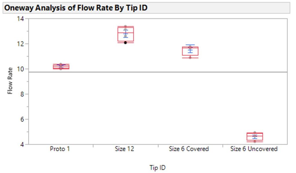
Flow rate analysis
A primary function of the device is to suction pooling body fluids away from the surgical site. The flow rate achieved by our prototype was compared to that achieved by existing suction tips currently used in the operating room. Prototype 1 was slightly slower than existing devices, which lead to the decision to adjust the inner geometry of the handle component. Prototype 2 was not evaluated.
Geometric Analysis in Context
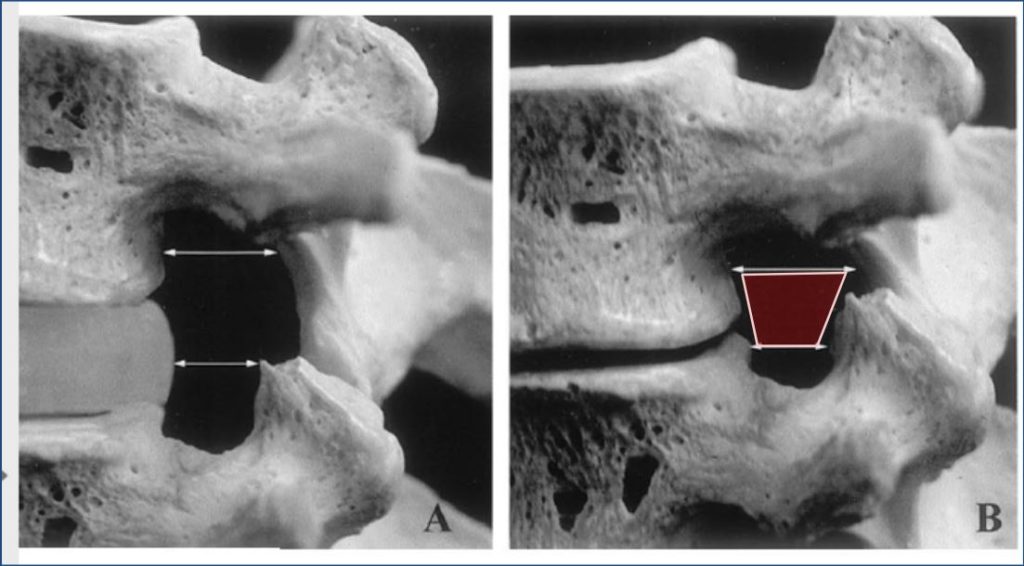
An important requirement of our device is that it works in the foraminal space while simultaneously allowing a cutting instrument – usually a kerrison rongeur – in the space. The foraminal cross-section varies widely by level and by patient, so an effort was made to quantify the occupancy of the space by current instruments and ensure our device matched that.
In the figure below, the left side represents a healthy patient, while the right side represents the limiting worst-case scenario with the disc completely removed. The cross-sectional area of the foraminal space was conservatively approximated to a trapezoid ranging from 78mm^2 to 94mm^2 for L5-S1 to L1-L2 respectively. With existing kerrisons and elevators currently used, it was calculated that the maximum current acceptable occupancy of this space is 50%. Therefore, we determined that our device combined with a kerrison could take up a maximum of 50% of this space.
Project progress and next steps
We have iterated through multiple prototypes of our device and done IP and regulatory reviews. We believe that with further development of the elevator paddle geometry, the device holds promise for patent protection and effectiveness. Given the COVID-19 crisis, we will be evaluating the potential for the project to be passed onto the next year of CMTI or BME students.