Team

Customer
Akm A. Rahman M.D., D.O., Diagnostic Radiology, University of Rochester Medical Center
Project Supervisor
Regine Choe Ph.D., Department of Biomedical Engineering, University of Rochester
Project Management Liaison
Katarina Lichak, CMTI, University of Rochester
Project Background
Introduction
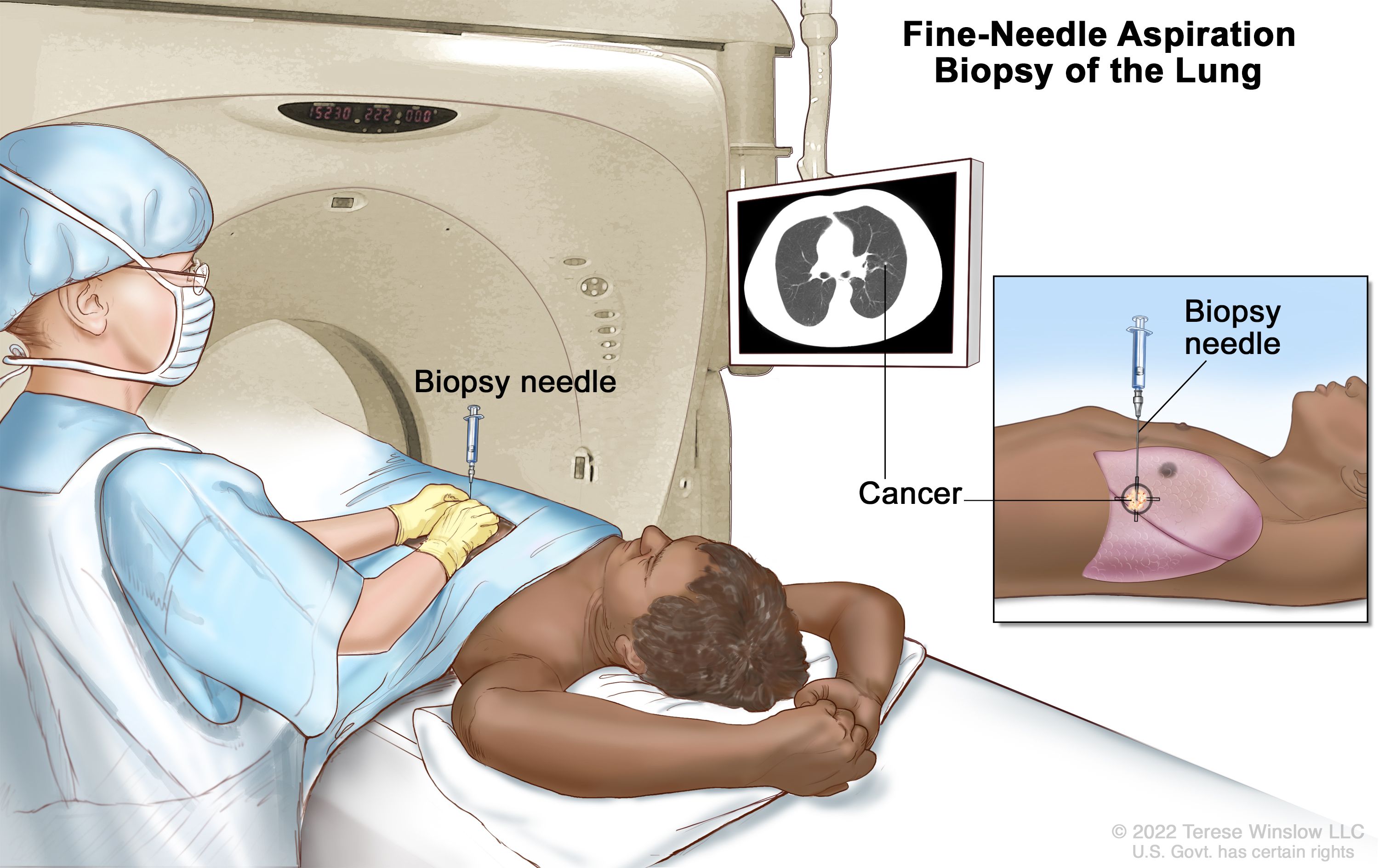
Computed Tomography (CT) is a widely used imaging modality that uses x-rays to provide a 2D scan of a 3D subject across one dimension. A CT-guided biopsy uses these images to locate a lesion and direct a needle into a patient’s body. Needle entry is carried out freehandedly by the physician at their approximation of an angle predetermined by initial CT scans. Advancement of the needle toward the lesion is also done freehandedly. Therefore, multiple CT scans are needed during the procedure to make sure the needle is on the correct path to obtain a sample from the lesion. Taking multiple CT scans is costly and increases exposure to harmful radiation, decreasing patient and physician safety. Therefore, our group proposed the Angle Device for CT-Guided Biopsy, a device intended to stabilize the biopsy needle at a set angle during CT-guided biopsies. Added stability reduces the number of intermittent scans required for CT-guided procedures, which then reduces overall radiation exposure and cost.
Scenario
In a CT-guided biopsy, the operating physician takes initial CT scans to obtain images of the region of interest (ROI). From these initial scans, the angle of entry to get to the ROI is determined by the radiologist or operating physician. The chosen angle depends on the depth and location of the ROI with careful consideration to avoid vasculature, integral tissue and bone to reduce complications [1]. During the procedure, the physician inserts the needle at their approximation of the predetermined angle. Entry and advancement of the needle are subject to the physician and are only estimates of the actual required trajectory [2]. Further, needle advancement along the correct path is dependent on the physician’s ability to stably advance the needle along the intended path. It is typical that CT scans are taken every 1-2 cm of needle advancement to assess needle trajectory and make the necessary adjustments [3]. This results in multiple scans being taken throughout the procedure.
Problem Statement
Our device aims to stabilize needle advancement by the operator during CT guided procedures to reduce the amount of imaging necessary. Reducing the rounds of CT imaging decreases patient and physician exposure to harmful ionizing radiation while also tackling the issue of inaccessibility in taking multiple CT images in low resource areas.
Design Concept
To begin approaching the design of this device, we first had to determine the features necessary for it to execute its function.
In our design process we chose to focus on the following requirements:
- The device has to be relatively inexpensive to be used in low resource settings with an aim of US$5 selling price.
- The device should allow for the advancement of a needle at a precise set angle to ensure that the needle can get to a lesion without many adjustments.
- The base of the device should remain stable on the patient to ensure accurate needle entry and advancement.
- The device material must be able to undergo pre-use sterilization, produce no imaging artifacts, be biocompatible and must be low weight to be used on a patient in the CT-suite in a hospital.
After identifying the needs of the device, we broke the device down into subsystems and focused on their interactions and functions. The three subsystems were the base, the two rotation systems and the needle holder.
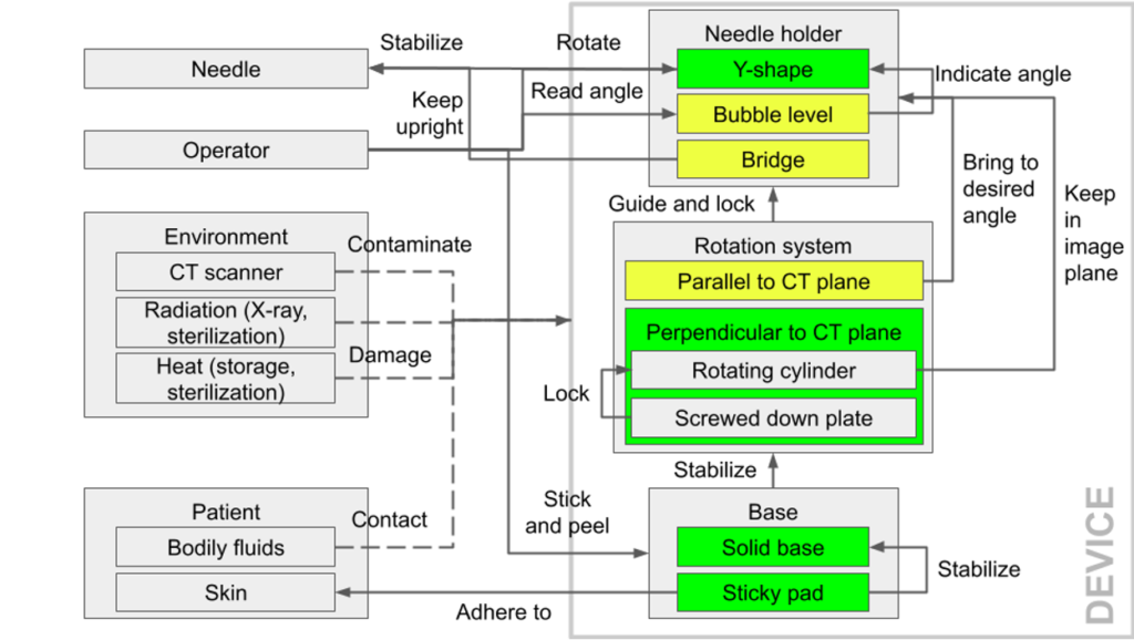
The base had to adhere to the patient’s skin and remain stable on the skin throughout the procedure.
There were two rotation systems: the base rotation system, perpendicular to the CT plane and the needle holder rotation system, parallel to the CT plane. Both rotation systems control the needle holder position and needed to be lockable at specific positions.
The needle holder had to be compatible with different needle sizes and allow for the needle to be stably advanced along it.
Prototyping Process
Every prototype following the initial one was 3D printed with ABS as the material. ABS was chosen because it is biocompatible, low weight, and sterilizable. It is also relatively inexpensive and produces no imaging artifacts in CT scans.
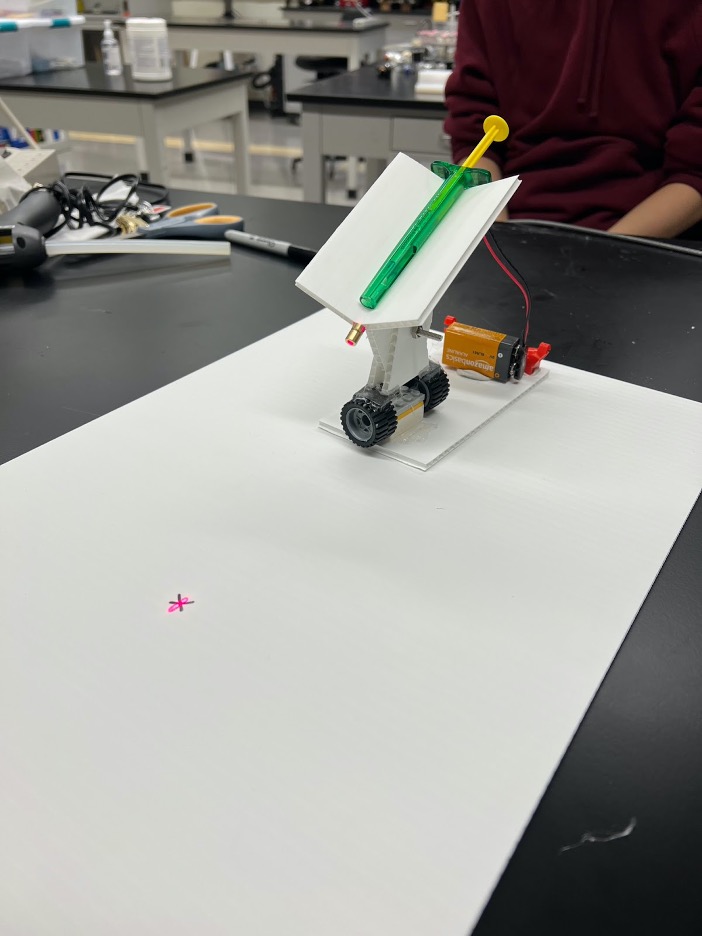
Prototype I
- Modeled after initial customer design from parts found in Senior Design Lab
- Needle holder made out of corrugated plastic and Lego wheels for the bottom rotation system
- Contains a laser pointer powered by a 9V battery attached to base
- Used to assess overall feasibility of the design and necessary improvements.
Points of improvement:
- Power source for laser needed to be smaller and lighter
- There needed to be locking mechanisms for both rotation points to hold the device at a set position
- There needed to be a feature to prevent the needle tipping backward
- The base should conform to body contour
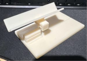
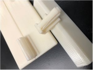
Prototype II
- Long Y-shaped needle holder that allowed whole needle to rest
- Featured an internal and external cylindrical rotation system
- Middle piece connecting needle holder and base snapped
- Base dimensions were 3 x 5 in with a midline notch
- Dimensioning for the rotation systems was too tight leading to cracking of the external cylinders
Points of improvement:
- Operation of device should be more intuitive for users
- The needle holder was too long
- The needle, with a heavy handle, should not tip backward in the holder
- The cylindrical systems dimensioning was too tight
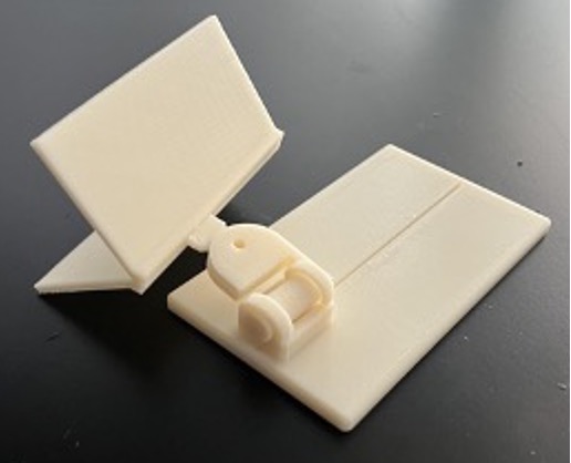
Prototype III
- Had a deeper Y-shaped needle holder to experiment with the design, half-inch shorter than in prototype II
- Base rotation dimensioning was too loose and did not fit locking mechanism design
- Base dimensions were 3×5 in with a midline notch
- New holder rotation design for smooth rotation and new locking mechanism
Points of improvement:
- There needed to be more rigid locking mechanisms for the rotation systems
- The needle holder length was too long
- The device height needed to be reduced to allow for the device to be used in the CT machine
- The base rotation dimensions had to be reduced to introduce more friction and allow for implementation of the locking mechanism
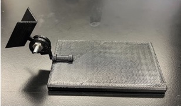
Prototype IV
- After viewing procedures, outlook on device drastically changed
- Creation of new cylindrical holder design for needle stability
- Dimensions of base reduced to 2.5 x 4 in, unintentionally left out the midline notch
- Dimensions of needle holder and middle piece reduced, middle piece connecting needle holder and base was flimsy and snapped
Points of improvement:
- The midline notch needed to be included to align with the CT laser
- The height of the connecting middle piece should be reduced and its thickness increased to prevent breaking under force
- The base rotation size should be increased to incorporate the locking mechanism
- There should be a device alignment feature to know the distance the device should be placed from the entry site on the patient’s skin
- The base should conform to body contour
- There should be a rotation handle to rotate the needle holder
- There should be visible angle markings to know the angle of the needle holder
Final Prototype
We designed two similar prototypes before settling on the final prototype – prototype VI.
Prototype V
- Created smaller base to put on top of a deformable base made out of cross stitch fabric, flexible plastic canvas, and gel tape
- Deformable base featured a midline marking
- Holder locking mechanism included a nylon screw and nut
Points of improvement:
- The locking mechanisms should hold the device firmly in place
- There should be a device alignment feature to know the distance the device should be placed from the entry site on the patient’s skin
- Integrate bubble level for device alignment with the reference plane
- There should be visible angle markings to know the angle of the needle holder
- There should be a rotation handle to rotate the needle holder
- The small base attached to the deformable base should be larger to allow for the locking mechanism to be implemented
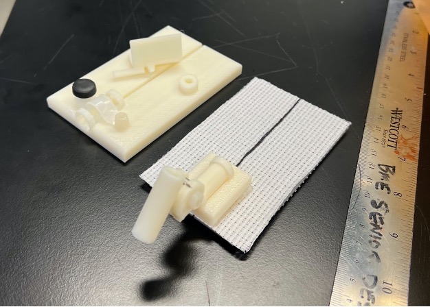
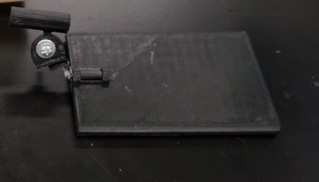
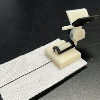
Prototype VI
- Features a ‘Y’ shaped holder with a cylindrical slot below the vertex for a slider to determine where the device should be placed on the patient relative to the entry site
- The needle holder has a rotation arm for ease of rotation
- It has a base wide enough for locking with a thumb nut
Points of improvement:
- The locking mechanisms should hold the device firmly in place
- There should be improvements on the device alignment feature to know the distance the device should be placed from the entry site on the patient’s skin
- Integrate bubble level for device alignment with the reference plane
- There should be visible angle markings to know the angle of the needle holder
Prototype Testing
Accuracy Test
The accuracy test was performed to compare the frequency of target ‘hits’ with and without the device. The test was performed with a large gelatin phantom, on a lesion 7 cm deep and 1.5cm wide. For 1 angle at 60 degrees, 10 trials were performed with and without the device for 6 people.
Results:
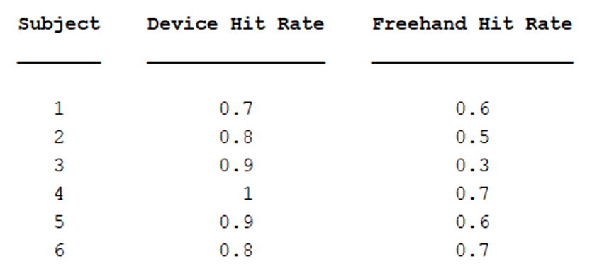
Using a paired t-test to analyze the results, more targets were hit with the device than without (p=0.0064). This suggests that using the device is more accurate than freehanded.
CT-Guided Procedure
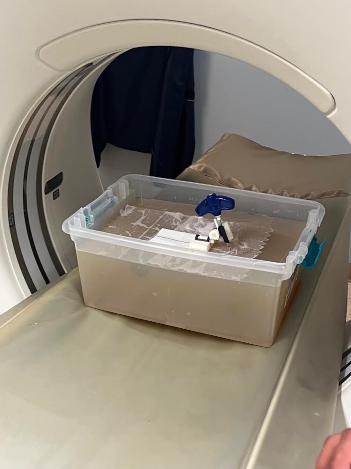
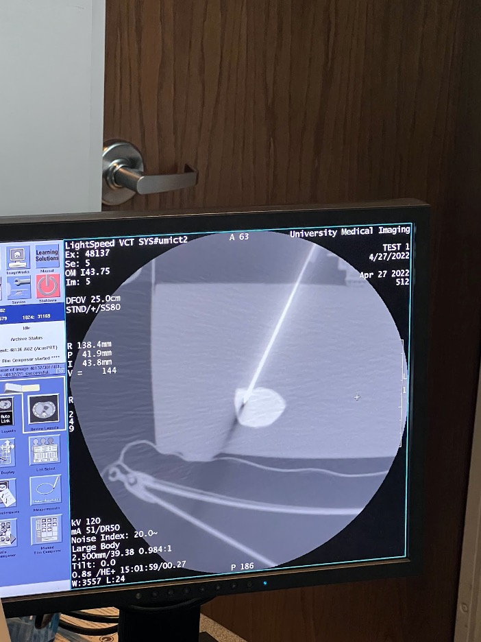
Our group had the opportunity to use a CT machine to image a gelatin phantom with sample lesions and to try out our device.
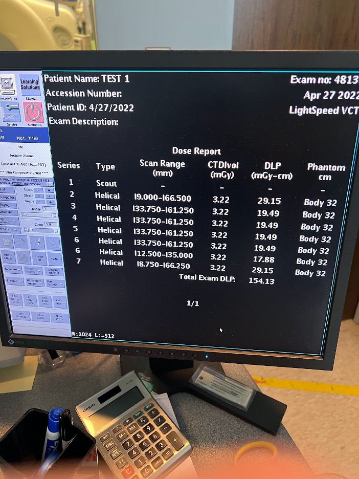
We performed a CT-guided biopsy on a gelatin phantom with and without the device to compare the number of scans it would take to hit a target. The result shows initial support for Dr. Rahman’s hypothesis that the device reduces radiation exposure by setting a firm angle compared to free hand biopsies. The target lesion was reached in 3 scans with the device vs. 4+ with the freehand attempt.*
This experiment showed the importance of the center midline and integration of the laser in later versions of the device. We would need to perform repetitions of this experiment and assess it at different angles to make any conclusions.
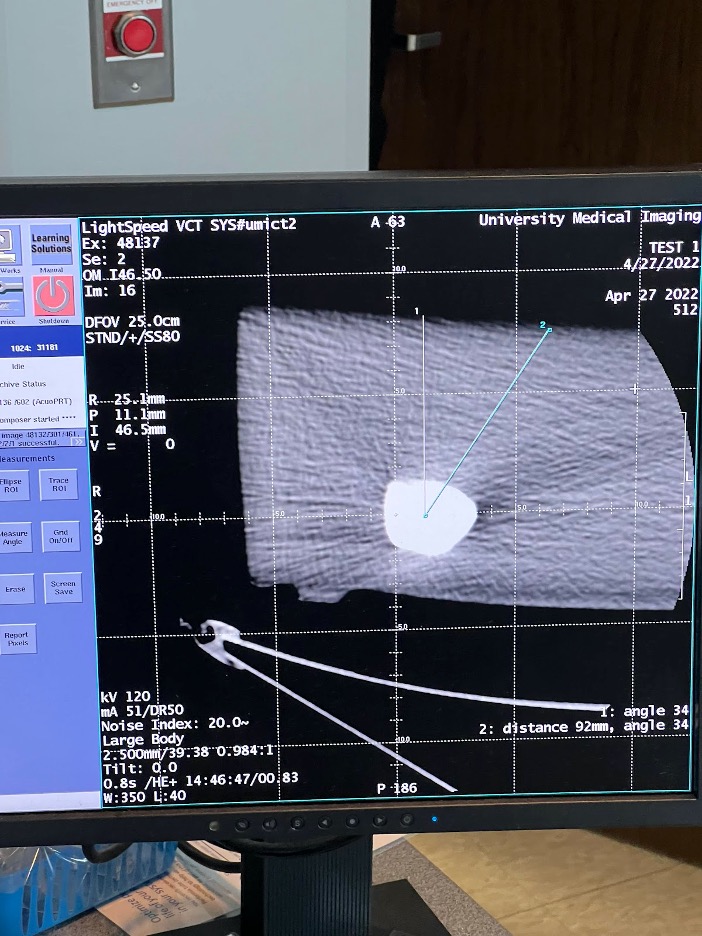
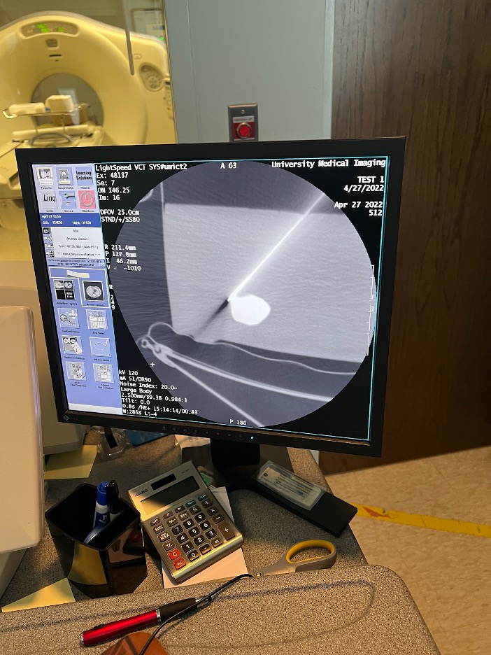
*The device attempt and freehand attempt were performed by different individuals.
Future Directions
As of now, we have a prototype that has been continuously improved upon since the beginning of the semester. The next steps for this device to be fully optimized for better use and mass production are as follows:
- Create a more flexible base – As seen in Prototypes V and VI, this base would be created directly out of a more flexible plastic, mimicking our design
- Insert a laser guide below the needle holder – this would require extensive research to align the laser guide and needle tip to the same spot on the patient’s body. The CT experiment highlighted the importance of this tool
- Transition to injection molding for mass manufacturing – most likely with a higher strength material that meets the material selection criteria
- Integrate bubble level for device alignment with the reference plane
- Improve base and holder locking mechanisms to lock firmly in place
- Include visible, refined angle markings for holder rotation
- Assess device functionality – more tests to determine accuracy, CT scan reduction, device stability
- Finalize medical-grade base adhesive tape that ensures device stability on patient
Acknowledgements
We would firstly like to thank our customer Dr Akm Rahman for bringing this idea forth as a senior design project, being available to answer our questions and providing the necessary support throughout the project. We would also like to thank Dr Alex Kessler and staff in Interventional Radiology at URMC for allowing us to view CT guided procedures and for answering our questions. Special thanks to Dr Regine Choe and Katarina Lichak for their guidance on this project every week from its conception. Finally we would like to thank the course instructors Dr Scott Seidman and Dr Amy Lerner for their guidance throughout the project as well as Jim Alkins for his help in 3D printing our prototypes.