Team
- Mathias P Hansen
- Joshua Jacobs-Rebhun
- Jae Hyun Kwak
- Thang C Le
- Elizabeth E Yarnall

GitHub Repository . Abstract . Sensors . ROS . Microcontrollers . Other Modules
Abstract
The Autonomous Bot for Campus Delivery (ABCD) is an autonomously controlled robot that will be used to deliver packages between buildings on campus. The robot combines several sensors and modules to effectively navigate between buildings and safely traverse the campus. Sensor data is interpreted by software written using the Python Robot Operating System (ROSPY) framework on a Raspberry Pi, which passes a right and left motor speed to a HERO Development Board that controls the motors. The main purpose of the ABCD is to assist ECM and academic groups that need materials transported between buildings for labs, workshops, events, etc. These items are currently delivered manually which is time-consuming.
Sensors

Ultrasonic
We are using three HC-SR04 Ultrasonic Distance Sensors. They can detect objects 2 cm to 400 cm away, with a range accuracy of 3 mm. The transmitter sends out an 8-cycle burst of ultrasound at 40kHz and the echo signal is detected by the reciever. Our Raspberry Pi measures the time delay and calculates how far away an object is.
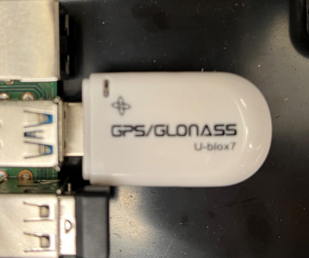
GPS
We are using the VK-172 G-Mouse USB module, which uses the G7020-KT chip and a ceramic antenna to recieve and interpret GPS signals.

Magnetometer
We are using a QMC5883L chip. This is a multi-chip three-axis magnetic sensor. It returns a compass bearing with an error of 1-2 degrees to the Raspberry PI using I2C communication.
ROS
ROS stands for Robot Operating System. It is a set of software libraries and tools that we are using to collect all of the sensor data and prioritize it to make decisions. Every sensor input is wrapped in a ROS node. They are connected to other nodes that manipulate the data and use it to make decisions that are passed to other nodes. This has been a very helpful and efficient communication framework for this project. For example, the path planning node takes in data from the collision detection, localization, and executive nodes. However, the collision detection node is given the highest priority because avoiding collisions is our highest priority.
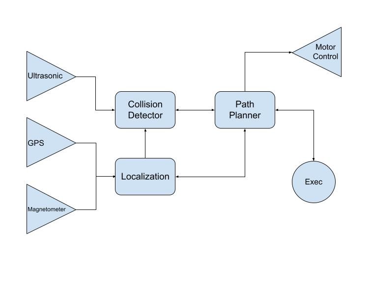
The three sensor input nodes send information to the localization (described in greater detail below) and collision detection nodes. The executive node implements the mapping algorithm described below. The path planner node sends and receives information from all three of above nodes to decide what intersection the robot is traveling to/from and therefore what direction to travel. It translates this into motor control instructions which are passed to the motor control output node.
Microcontrollers
Raspberry Pi
We are using the Raspberry Pi 4 Model B to manage the sensor inputs, user inputs and mapping algorithms. ROS has been installed and executes the communication framework as described above. The Pi reads sensor input from its UART, I2C and digital I/O pins. When motor control decisions have been made by the ROS module, the Pi sends two bytes to the HERO Development Board over UART.
HERO Development Board
The HERO Development Board receives two bytes from the Pi, that it uses to set the speeds of the right and left motors. It scales the value originally received (0 to 255) to a floating point integer (-1 to +1). This value is passed to the motor drivers, causing it to accelerate or turn. This is what allows us to control the speed and direction of the robot.
Other Modules
Path Planning
To determine the shortest path to take, we use an implementation of Dijkstra’s algorithm in Python. This program takes in a list of intersections, the paths that connect them and the length of every path. When we pass it a start and end intersection, the shortest path between the two is returned as a list of intersections.
Robot Feautures
The base of the robot is an Outdoor Rhino Track Drive with four 2.5 inch CIM Motors, powered by a 12-volt DC supply. The HERO Development Board controls these motors. The robot can switch from an autonomous mode, to manual control with a Logitech Wireless Gamepad instantaneously.
Localization
To determine its current location, the system uses the Extended Kalman Filter algorithm. We cannot rely on GPS readings alone, because the range accuracy is about 2 meters. Instead, it considers the current GPS and magnetometer readings, as well as the history of actions it has taken to compute a best estimate of its current location.
Image Processing
Overview
While we were not able to implement any image processing, we researched and attempted many approaches. The image processing for our project ultimately had three different goals. The first is for the robot to stay on the road during its time of travel, the second has to do with the robot detecting the obstacle during the journey, and the third has to do with its action when it finds an impediment during the travel. To do so, we had to exploit OpenCV camera calibration. General structures for the code for image process goes when the camera that records the video of travel may capture every moment, but as it does that, it will capture the picture in coordinates in a way we want it to be captured. However, it is not just simply about taking photos of each action of the movement, but more about detecting where the actual road is for the travel. First of all, the trajectory should be seen. Then, based on the approximate height and width of the road we have set, the camera image will be able to detect path strips or lanes of the way as well. Based on whether the line for the path gets noticed, it can be shown through colors that we can get through HSV or simply by the way we designate it.
HSV
Lanes are found from the image that has been captured when there could be a color distinction within the paths that the robot runs on. However, for the lanes we have on campus for our ABCD project, we don’t necessarily have ‘pathways’ just like many image processing exploits. Therefore, one approach we did was to blur out every green color to black and white that way robot only runs on the path that is not green, which would not be the grass. We need to put restrictions on the HSV (Hue Saturation Value) to do that. We can blur all 120-180 HSV values that are green and set those to black and white instead. These schemes show how colors could be combined to create multiple spectrums.
NMS
Image processing becomes essential for the robot to recognize that humans and objects could be anywhere its travels. Although there are sensors attached, we still need to detect whether the robot is heading on a safe path and maintain the safety of others as well. As a result, the importation of NMS comes into a central role in image processing. Non-Maximum-Suppression is a technique to filter the predictions of the object while it travels. The camera captures more than one photo in a short movement; it will take multiple pictures and create a box around an unknown object based on the coordinate. However, that will make things overlap, and what NMS does is put those overlapping boxes in one to show that there is only one obstacle hindering the path.