Table of contents
- Problem statement
- Team members
- Background information
- Our prototype
- Mechanical testing and prototype assessment
- Next steps
- Acknowledgements
- References
Problem statement
In order to train surgical residents effectively before operating on a patient, the use of simulation tools has increased. The medical simulation market does not currently offer a product that realistically represents haptic feedback of the knee during key movements of total knee replacement surgery (TKR), so we are designing a model with stiffnesses more reflective of the native knee. We are working with Sawbones, a company that manufactures these simulators which provide realistic feedback of bone during the use of an oscillating saw.
The goal of this project is to create a knee model that allows residents to understand the forces they will be feeling from the structures around the knee during surgery. This will allow them to be trained efficiently, be more prepared going into surgery, and improve patient outcomes.
Team members

Supervisors
Kanika Vats, PhD, Biomedical Engineering, University of Rochester
Samantha Ring, CMTI student, University of Rochester
Customers

Background information
Total knee replacements (TKR) are one of the most common orthopaedic procedures – 2.6 million total knee replacements are performed globally every year (Stewart, 2019). Orthopaedic surgical residents must learn and practice this procedure. As part of their training, orthopaedic residents perform skills labs using simulation models such as the ones sold by Sawbones to learn and practice their skills outside of the operating room without patient risk. Current models help the residents learn the steps, tools and feeling of cutting into the bone but it does not give them an overall realistic stiffness provided by soft tissues surrounding the knee joint. One of Sawbones’ current models used for benchtop simulation are connected by two materials: latex stretch tubing representing the lateral collateral ligament (LCL), medial collateral ligament (MCL), and posterior cruciate ligament (PCL); and stretch cloth representing the patellar and quadriceps tendons.
One of the current Sawbones models is shown below.
The steps of this procedure include moving the patella (knee cap) to the side, cutting the femur, tibia and patella surfaces to prepare them for the implant, placing the implants and checking that the knee is properly balanced.
Specific movements we focused on
While there are several steps in a TKR procedure, there are a few motions in particular that require surgeons to apply a significant amount of force on the knee joint. Our customers asked us to focus on creating a model with a realistic feeling in these three key motions: (1) anterior displacement of the tibia, (2) subluxation of the patella, and (3) varus/valgus movement.
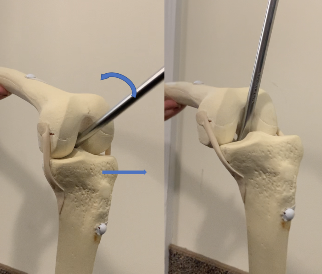
(1) Anterior displacement of the tibia
This step exposes the tibial surface so that the tibial cut can be performed. A retractor is placed on the posterior side of the tibia and the tibia is pushed forward.
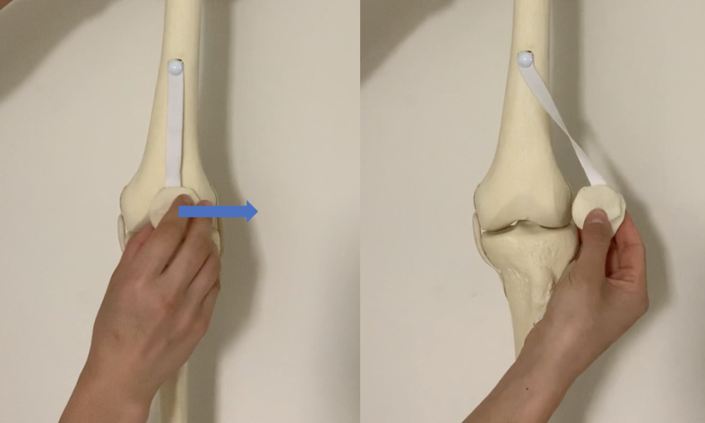
(2) Subluxation of the patella
This step exposes the underside of the patella in order to place the patella implant. The patella also needs to be held out of the way through the rest of the procedure to perform the cuts and place the implants.
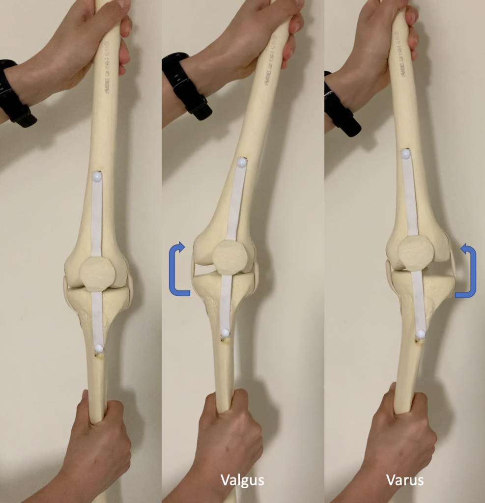
(3) Varus/valgus movement
The tibia is moved medially and laterally after the implants are in place to ensure that the knee is properly balanced on both sides. This is done in flexion and extension to ensure the knee is balanced at all angles.
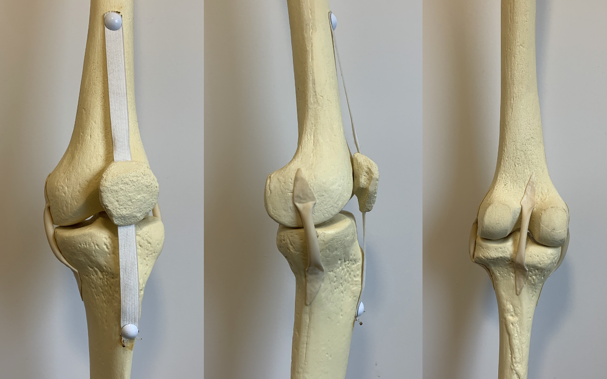
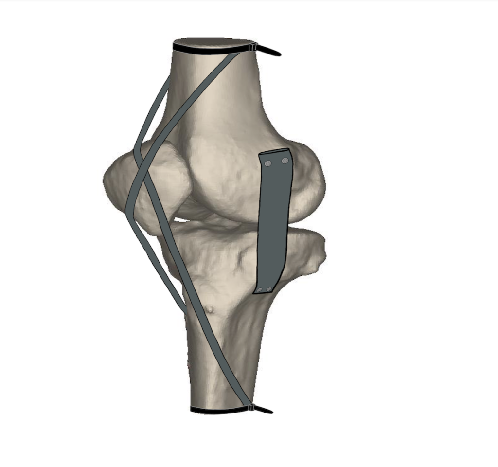
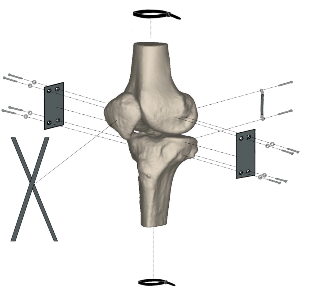
Our prototype
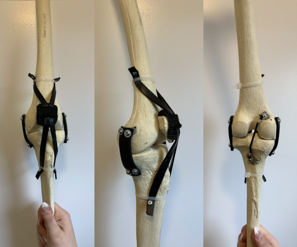
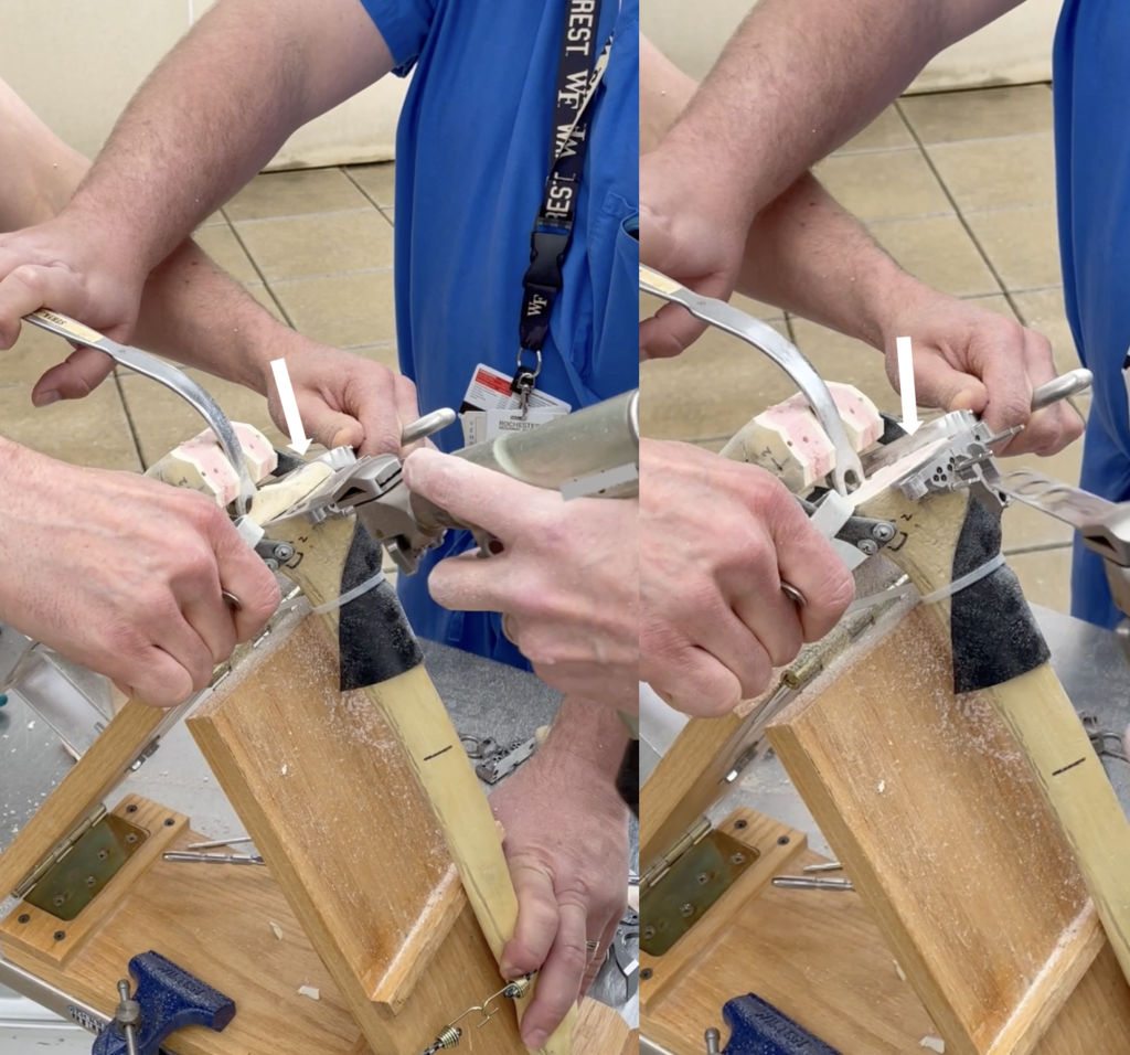
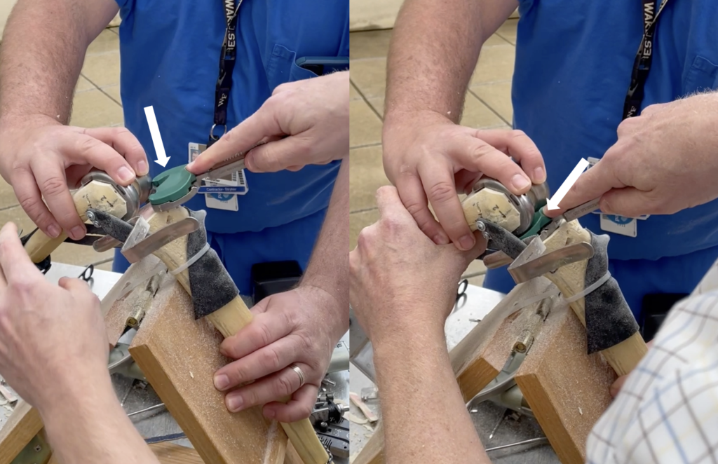
Our design contains a tibia, femur, patella, LCL, MCL, PCL, and extensor mechanism. The main subsystems include the ligament-attachment-bone interactions, where the ligament materials are attached to the sawbones. We have strived to create a model with as many homogenous materials as possible, such that all of our ligaments are made of 60A and 70A EPDM. The main attachment mechanisms are machine screws and washers to secure the ligaments to the bones, and zipties are used to hold the extensor mechanism in place.
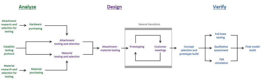
Design process and project workflow
Shown below is the overall approach we took to designing our prototype. We started with conducting mechanical testing on the individual components, such as the ligaments and attachments. Using this knowledge we built full prototypes and conducted full knee testing and qualitative assessments.
Mechanical testing and prototype assessment
Our design process began with mechanical testing of attachment and ligament materials to select secure attachment mechanisms, and determine which materials had mechanical properties most reflective of native tissues in the knee. After testing several materials and methods, we were able to finalize material selection and create more prototypes with the aim of reflecting a realistic feel of the knee model overall. Through multiple in-person and virtual meetings with our customers, we were able to evaluate our prototype and receive helpful feedback.
To quantify whether our knee behavior was realistic in the key movements we focused on, we performed full knee testing to assess varus/valgus stiffness and range of motion. To validate the final iterations of our prototypes, we had the opportunity to meet with a few orthopaedic surgeons for qualitative assessment and Dr. Myers also performed a TKR simulation on our prototype.
Attachment and ligament material testing
Attachment testing
The team used stacked cinder blocks, two large C-clamps, wooden blocks, foam cushioning, rope, and interchangeable dumbbell weights to test the attachment mechanism.
The team tested a total of six attachment mechanisms in both uniaxial and shear tension by hanging a 30 lb weight from a rope attached to the attachment mechanism for 5 minutes to ensure that it would not deform over time.
The determination was made that our attachments should withstand 30 lbs because we assessed that orthopaedic surgeons are applying about 10 lbs of force to the leg at the middle of the tibial diaphysis to test varus/valgus alignment which are the conditions in which the surgeon is applying the most force. With that in mind and the goal of testing to a factor of safety (SF) of >3, we decided to test each attachment to 30 lbs.


Attachment testing apparatus for the following methods: rope threaded through bone, screws & washers with drywall anchors, and cyanoacrylate applied to neoprene sheet.
Ligament material testing
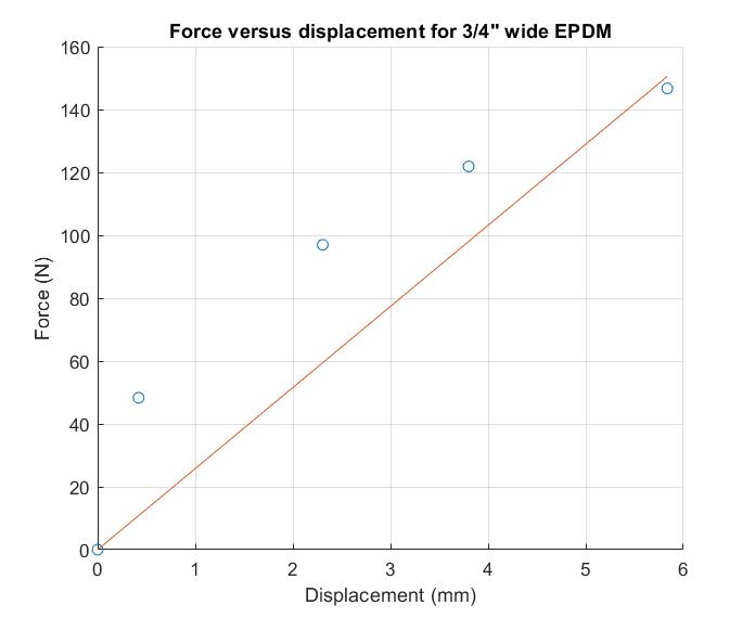
We performed at-home uniaxial tensile testing on 11 materials to determine the stiffnesses of potential ligament materials. We marked fiducials on the central regions of these materials before securing both ends of the specimens between clamps; wooden blocks with sandpaper were placed between the C-clamps for gripping. For each material, 5 different loads were hung from the bottom clamps during successive increments and the distance between fiducials was measured for each increment.


Ligament testing apparatus and measurement of distance between fiducials.
To analyze this data, we created force-displacement curves for each of these materials and used linear regression analysis to determine the stiffness of the materials in the force regions of interest for the purposes of our model. We determined that the EPDM strap material had the highest stiffness out of the materials we tested and had material properties closest to the target values for collateral ligament stiffnesses of 60 – 100 N/mm (Momersteeg, 1995).
Governing equation:
stiffness = force / displacement
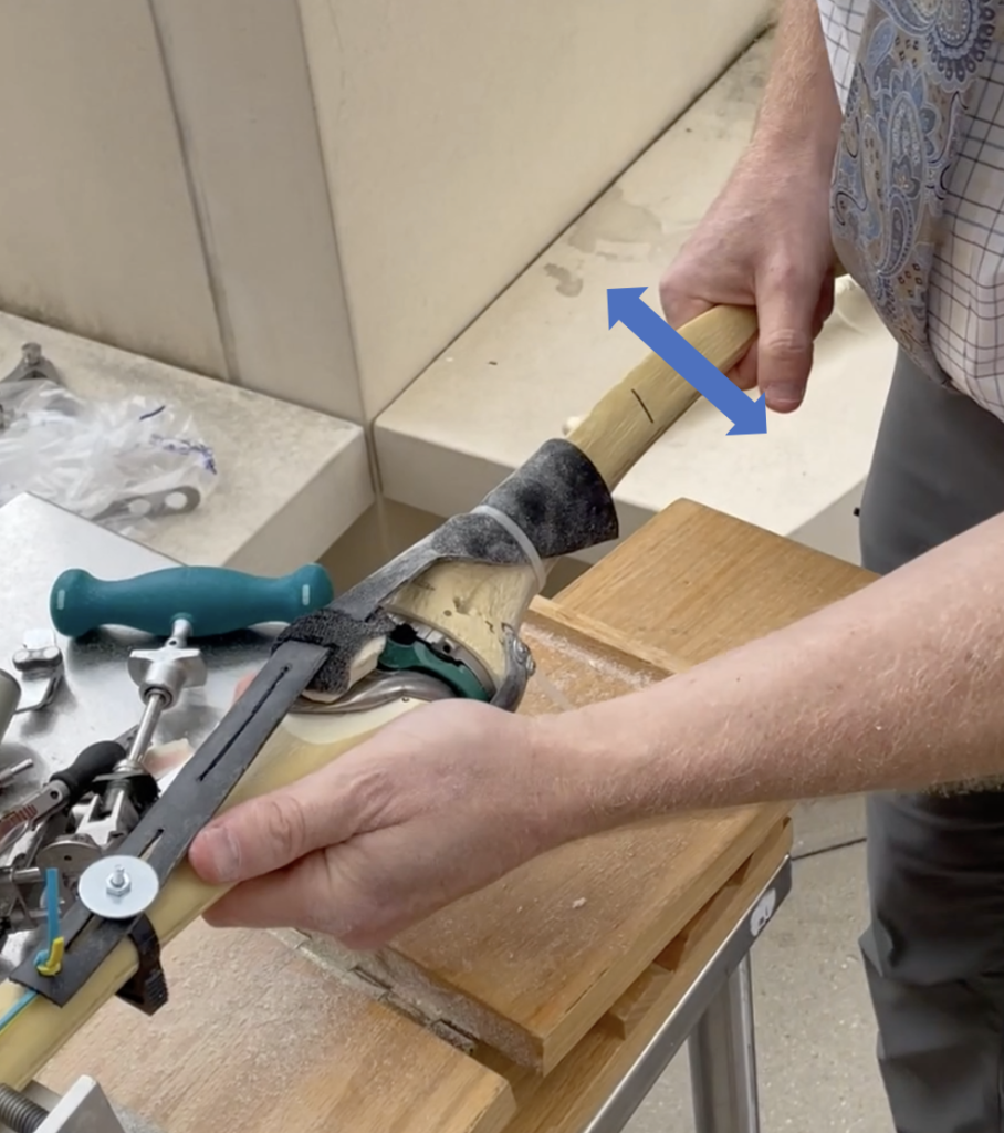
Varus/valgus testing
In order to test the stiffness of our model in varus and valgus we conducted at home testing where we mounted the femur in place and induced a moment on the tibia by attaching a force gauge at a defined distance and applying a force. A video was taken as progressively more force was applied to the tibia. Several frames of the video were then analyzed in ImageJ to measure the displacement angle and force applied at that point. The moment was then calculated, leading to the derivation of the angular stiffness which is derived as the moment per degree of displacement.
Governing equations:
Moment = (Force)*(Distance)
Angular Stiffness = (Moment)/(Angular displacement)
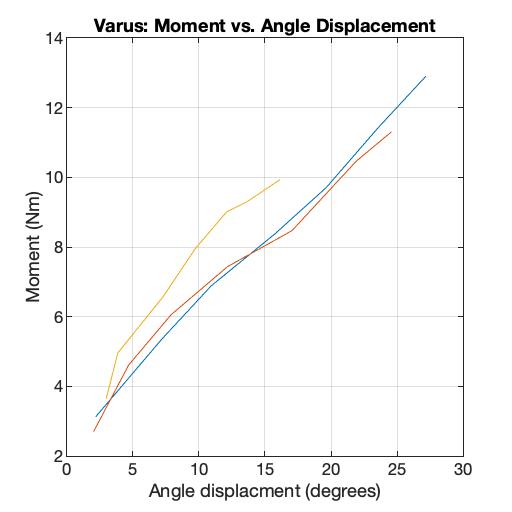
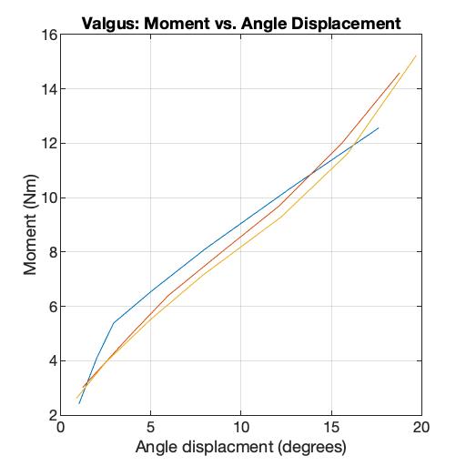
Shown above are the moment versus angle displacement graphs for the varus and valgus motions. The resulting stiffnesses for valgus motion ranged from 0.7-3.03 Nm/º and for varus it ranged from 0.46-1.43 Nm/º. Both of these stiffness ranges are within the range of 0.5-11 Nm/º from the literature (Schmitz, et al., 2008, Markolf, Mensch, Amstutz, 1976, Creaby, et al., 2010)..
Range of motion
The range of motion of our model was tested using a goniometer in flexion and extension. It was determined that our model could achieve the necessary range of motion angles in both flexion and extension (0-110 degrees) (ASTM Standard F2083 – 21).
Qualitative assessment by orthopaedic surgeons
Further evaluation of our model was assessed by Dr. Myers and three orthopedic surgeon colleagues of Strong Memorial Hospital. Each physician took turns feeling the model in the three key TKR motions that we have identified. This provided us with a qualitative assessment of the stiffness of the knee and further understanding of various surgical techniques employed by different providers. Overall, the majority of surgeons thought our model realistically represented the stiffness of the knee in varus/valgus motion, the anterior displacement of the tibia, and the extensor mechanism had the correct uniaxial stiffness, but did not provide realistic lateral resistance during subluxation of the patella. We have since implemented a new extensor mechanism in our model to more accurately represent the movement of the patella.
Surgical simulation assessment
In order to assess our models ability to be used for a total knee replacement simulation we had our customer, Dr. Myers, perform the entire procedure on one of our earlier prototypes. He performed all the steps including the femoral and tibial cuts, fitting the implants and checking the balance of the knee afterwards.
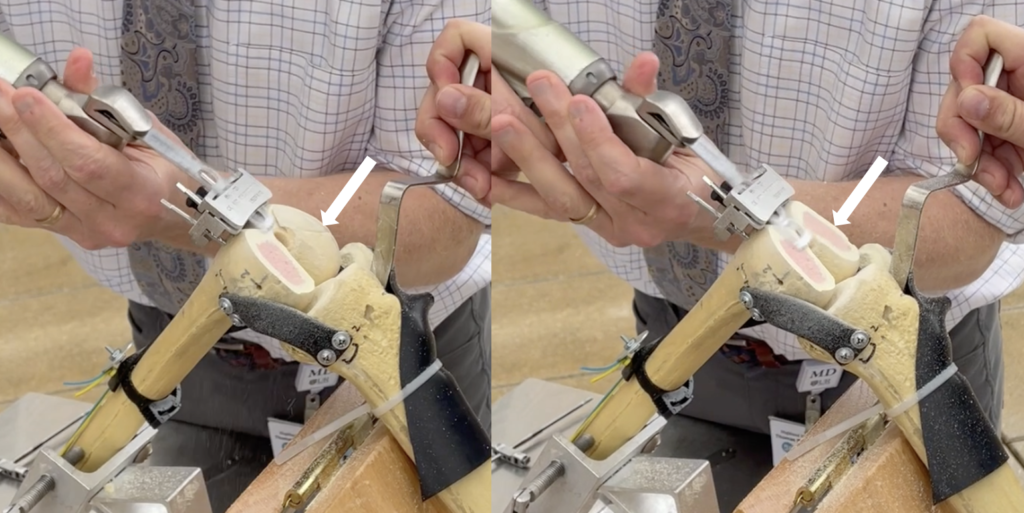
Through this simulation, we were able to assess if there were any interactions between our model and the tools. We found there were two areas of interaction between the drill used to attach the cutting guide to the bone and our attachment mechanism. This was an earlier prototype where the attachment mechanism was longer screws with drywall anchors. We have since changed this mechanism and believe there will no longer be this interaction.
This simulation also gave our customer the chance to assess if this model is sufficient enough to test the resident’s ability to select the right size for the plastic tray insert. Dr. Myers was able to feel a significant difference between different sizes and believes that our model could be used for this purpose.
Next steps
As a result of the feedback from full knee testing and assessment by various orthopaedic surgeons, we developed a new extensor mechanism concept to improve the behavior of the knee during subluxation of the patella. We provided this to Dr. Myers for his assessment and he felt that the behavior was more realistic than the previous iteration, specifically in lateral patella movement. Beyond the scope of this project, however, we recommend that Sawbones conducts further mechanical testing on this new design to ensure this new concept is secure and to better understand the wear behavior of this mechanism.
Manufacturing Considerations
We recommend that Sawbones recruits a group of manufacturing engineers to determine the best ways to manufacture the ligament components and integrate those processes into their current manufacturing lines. This may include processing sourced goods, hiring a third-party manufacturer, or molding the components themselves. This will also be highly dependent on their production volume and the anticipated market growth over the next 5-10 years. Additionally, it will be essential to determine tolerances for each component so that each model performs accurately.
Market Information
The current global medical simulation market size is valued at an estimated 3 to 4 million USD, with full knee surgical simulators like our product being valued at about 10% of this market (James, 2021). According to the American Academy of Orthopaedic Surgeons, there are 150 orthopaedic residency programs in the United States alone, equaling over 3,000 residents (UW Medicine: Orthopaedics and Sports Medicine). Due to the need to train this volume of residents efficiently, effectively, and safely, we believe there is a high demand for using surgical simulators for teaching purposes.
Acknowledgements
We would like to thank our customers John James and Amy Posch for answering our many questions and for sending us materials from Sawbones. We would especially like to thank Dr. Myers for having meetings with us at Highland Hospital to evaluate our model and for providing us with the opportunity to meet with other orthopaedic surgeons to receive their feedback. Thank you to Scott Brugler from Stryker for inviting us to the skills labs to gain an understanding the environment for our product and to see the surgical equipment used during these simulations. We would also like to thank Art Salo for his willingness to assist us and for cutting some of our materials for us. Thank you to Bill Schierwagen for providing the team with tools, equipment, and materials throughout the course of the project as well as your knowledge of mechanical processes. Lastly, we would like to extend our thanks and appreciation to Dr. Lerner, Dr. Seidman, Dr. Vats, and Samantha Ring for meeting with us throughout the past two semesters and providing us with very useful feedback.
References
ASTM International. (2011). ASTM F2083 − 21: Standard Specification for Knee Replacement Prosthesis. In Annual book of ASTM standards 2011 (pp.988-995). West Conshohocken, PA: American Society for Testing and Materials. doi: 10.1520/F2083-11.
Creaby, M. W., Wrigley, T. V., Lim, B. W., Bowles, K. A., Metcalf, B. R., Hinman, R. S., & Bennell, K. L. (2010). Varus–valgus laxity and passive stiffness in medial knee osteoarthritis. Arthritis Care & Research, 62(9), 1237-1243.
How to obtain an orthopaedic residency. (n.d.). UW Medicine: Orthopaedics and Sports Medicine. Retrieved May 1, 2021, from https://orthop.washington. edu/sites/default/files/ossmig/AAOS%20How%20to%20obtain%20Orthoresidency.pdf
James, J. & Posch, A. (2021, April). Personal Communication [email].
Markolf, K. L., Mensch, J. S., & Amstutz, H. C. (1976). Stiffness and laxity of the knee–the contributions of the supporting structures. A quantitative in vitro study. JBJS, 58(5), 583-594.
Momersteeg, T. J. A. et al. (1995). The effect of variable relative insertion orientation of human knee bone-ligament-bone complexes on the tensile stiffness. J. Biomech. 28, 745–752.
Schmitz, R. J., Ficklin, T. K., Shimokochi, Y., Nguyen, A. D., Beynnon, B. D., Perrin, D. H., & Shultz, S. J. (2008). Varus/valgus and internal/external torsional knee joint stiffness differs between sexes. The American journal of sports medicine, 36(7), 1380-1388.
Stewart, C.J. (2019). Demand for knee replacement grows 5 percent worldwide. OrthoSpineNews. https://orthospinenews.com/2019/06/04/demand-for-knee-replacement- grows-5-percentworldwide/#:~:text=ST., knee%20replacement %20surgery%20each%20year.