Team
- Thomas Anderson
- Liying Lin
- Scott Smith
- Yuyao Tang
Mentor


Abstract
Core courses and advanced electives in the University of Rochester undergraduate ECE program require a platform to experiment with and evaluate designing control systems. In order to solve this need, our team designed a two-wheeled robot with a two degree of freedom arm that doubles as a kickstand.
Project Description
Problem Statement
- Undergraduate ECE education requires test platforms for designing control systems.
- It is important to the ECE undergraduate teaching staff to have a balancing robot because 2 wheeled robots are becoming far more common and being able to design these control systems is a great skill to have in the industry.
- Core courses and advanced electives in the University of Rochester undergraduate ECE program require a platform to experiment with and evaluate designing control systems. This team will design, develop, implement and test a self-balancing robot testbed to satisfy these requirements.
Requirements
- Chassis must not undergo permanent deformation when supporting the robot upright
- On board power system should allow the robot to drive for long enough to test the control system sufficiently
- Must use a closed-loop control system rather than a mechanical solution for balancing when powered on
- Data port must be accessible from the outside without any tools
- Wheels must be independently controlled
- Must be able to balance on 2 coaxial wheels
- Robot must be stable when powered off with mechanical support
Specifications
- Robot must be able to drive using on board power for 12 minutes minimum. Measured from start up to battery death.
- Robots must take less than 3 hours to assemble from scratch based on the manual. This will be estimated from the assembly manual.
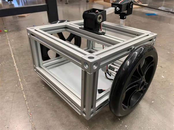
- Chassis must be able to balance on 2 wheels. This is visually obvious.
- Component cost per robot must be less than 800 dollars. This can be computed from a components list and their costs.
- Two wheels of the robot must be on the same axis. This is visually obvious.
- The volume of the robot’s frame must be less than 726 cubic inches. (Fit in an 11’x11’x6’ cube). This will be measured with rulers.
Concepts
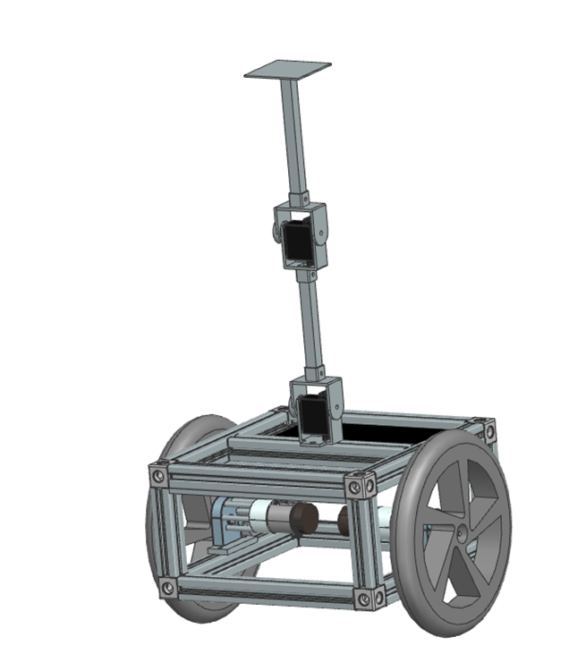
The team started by generating 4 different concepts. The lowest complexity concept contains only a box-like chassis with all electrical components in it and 2 wheels. It has a passive kickstand that is not deployed. The 2 second concept has the exact same design, but instead has an active kickstand that is not used for balancing. The third concept is a little bit complicated than the second one. It has almost the same design as the standard one, but the kickstand is also used for balancing and has two joints. The fourth concept is the most complicated one, with 4 wheels, but with two of the wheels on the end of two arms so it can change between balancing and not balancing. We chose the medium complexity robot with a double-jointed arm to allow for higher complexity of the control system.
| Criteria | Low Complexity | Low-Median Complexity | Median Complexity | High Complexity | Importance |
| Ease of Design | Baseline | – | – | — | 3 |
| Ease of Manufacture | Baseline | – | – | — | 5 |
| Cost | Baseline | – | – | — | 2 |
| Reliability | Baseline | – | – | – | 3 |
| Effectiveness | Baseline | + | ++ | + | 10 |
| Maintenance | Baseline | s | s | – | 2 |
| 0 | -3 | 7 | -15 |
Analysis
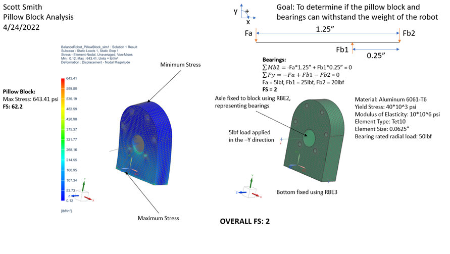
Since such large 8020 stock was used to build the robot, the chassis strength was not analyzed as it would be far stronger than required. Instead, the drivetrain was analyzed to ensure that the correct parts were ordered, and the pillow block would not fail. Results can be found below. The overall drivetrain has a Factor of Safety of 2, which is allowed given the relatively low uncertainty associated with the analysis.
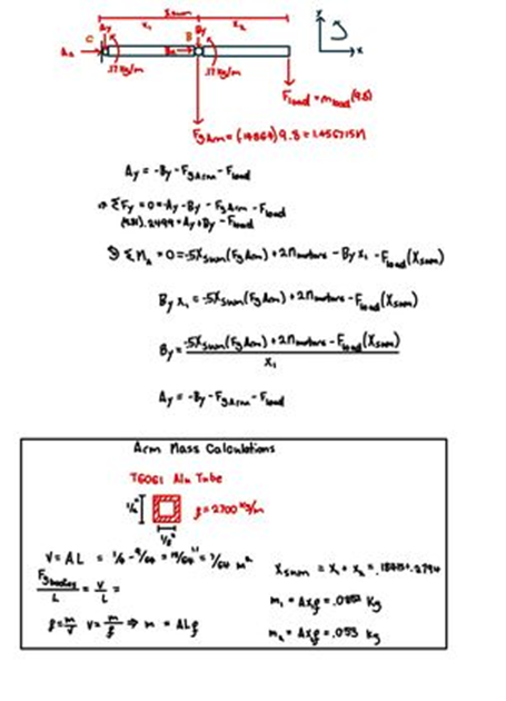
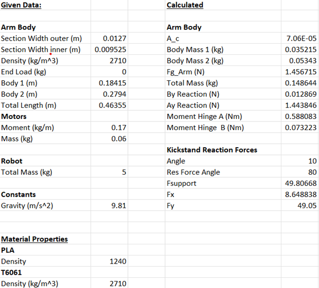
Static analysis was carried out on the arm to make sure that the servos would be able to manipulate the arm at any given point in their travel. This analysis can be seen below. The servos used are within the torques needed.
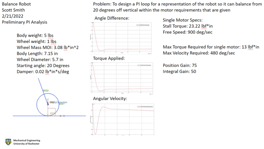
Dynamic Analysis was run on a simplified version of the robot to choose the correct gear ratio for the selected motors. After this analysis was run, A Pololu 37D 24v motor with 70:1 reduction was selected. Results can be seen below.
Manufacturing
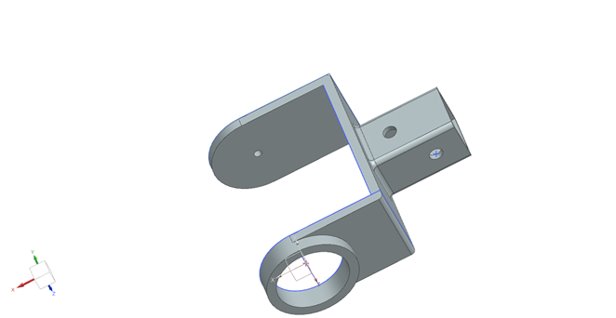
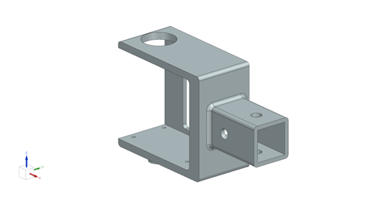
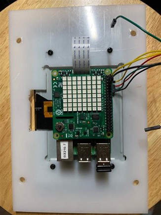
Since this robot is supposed to serve as a testbed for ECE students to learn about control systems with, many of the manufacturing decisions that were made were done to make the robot as simple and as quick as possible to manufacture. 3D printing was used extensively for fabricating parts like the arm hinges and wheel guards mainly because it’s cheap and requires little manual labor to do, which is important given that people who aren’t necessarily experienced with working in a machine shop would be tasked with building these in the future. The pillow blocks that mount the motors to the 8020 frame were chosen to be CNC machined for a similar reason, and because simulations showed that they endured much higher forces than what a 3D printed part could necessarily handle. We chose to make the chassis out of cut pieces of 8020 and compatible corner connectors because it was quick and easy compared to fabricating an entire frame from scratch using another method. If we were to scale this robot to be made in a higher volume such as 1000 parts, we could cut down build-time and cost by doing several things. Firstly, we could make the 3d printed parts such as the hinges and wheel guards with injection molding, while molds can cost several thousands of dollars, this would save us a lot of time since injection molding is a much faster process to do than if you were to print the same part on an FDM machine. We could also save time and money on building the frames by programming a CNC to cut the holes needed in each piece of 8020 as part of a batch rather than drilling them out using the manual mill.
Test and Results
In order to check if the robot met the specifications, we tested each in turn to see if they passed. The results can be seen below in Table 3.
| Specifications | Test | Result |
| Robot must be able to drive using on board power for 12 minutes minimum. Measured from start up to battery death | Drive the robot with full batteries continuously until it dies or until it exceeds 12 minutes of runtime | Unknown |
| Robots must take less than 3 hours to assemble from scratch based on the manual. This will be estimated from the assembly manual | Time a person who has not built the robot before with assembling one | Unknown |
| Component cost per robot must be less than 800 dollars. This can be computed from a components list and their costs. | Check to see if the sum of material and labor costs is less than $800 | Passed |
| Two wheels of the robot must be on the same axis. This is visually obvious. | Look and see if they are on the same axis. To be even more exact, measure how far both wheels are from the same end. | Passed |
| The volume of the robot frame must be less than 726 cubic inches. (Fit in an 11’x11’x6’ cube). This will be measured with rulers | Measure the frame with rulers | Passed |
| Chassis must be able to balance on 2 wheels. This is visually obvious. | Have the robot balance itself on only its wheels with code | Possible, yet to be successfully tested |
Future Step
Currently the arm at the top only works as a kickstand when the robot is not in used. When testing the robot, the arm will be locked at the top and does nothing. Future work will focus on how the arm would help in self-balancing. The goal is to make the arm adjust its position to keep the chassis in balance.
Besides, we will design a “gripper” for pick up stuff at the end of the arm, and therefore more analysis when holding objects are needed.
Societal and Environmental Implications
As a learning aid for students to test their code, the biggest impact this robot will have is on the next generation of Electrical engineering students to come out of the from the University of Rochester. Having a physical robot to test code on will give students the opportunity to apply the control theory they’ve learned into balancing and driving a two-wheeled robot. In terms of environmental impact, the extensive use of 3D printed parts creates a lot of plastic waste from the plastic supports that must be printed with the parts. Along with this, there is also a fair bit of metal wasted in making the pillow blocks since they’re made with the subtractive process of CNC. If we were to reduce the amount of wasted material, we could do so by creating low-volume injection molds of the plastic parts as well as by casting things like the pillow blocks and then doing a small amount of machining for the different holes.