Team
- Anis Idrizovic (Team Leader and Project Coordinator)
- Yuchen Wu (Primary Lens Designer)
- Hangyue Zou (Secondary Lens Designer and Researcher)
- Steven Scheidt (Meeting Scribe and Document Management)
Mentors From Circle Optics
Andy Kurtz
John Bowron
Robert Metzger
Vision
This year Circle Optics wanted to explore the fully reflective optical design space, particularly how it can be applied to their current signature design form. Our task was to perform an optical design study in the fully reflective space, using different numbers of mirrors and different surface types to achieve a parallax controlled wide FOV fully reflective hyperspectral system design that could be bundled with copies to form a full ring of vison. The end goal of our project was to create one or more designs that could be used as a starting point for expanding Circle’s manufacturable arsenal of parallax controlled designs into the fully reflective space. We’d also include documentation detailing what things to aim for or avoid while they pursue further designs in this space based off of our explorations.
Background And Parallax
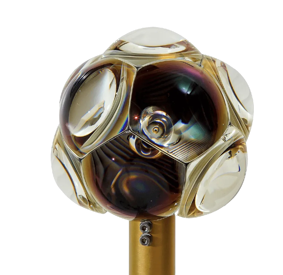
Circle Optics is know for their Hydra Alpha design, and is in the process of producing their Hydra Beta. Circle Optics uses parallax controlled optical channels to construct a system that requires greatly reduced processing time to produce a stitched image over as many as 11 different sensors.
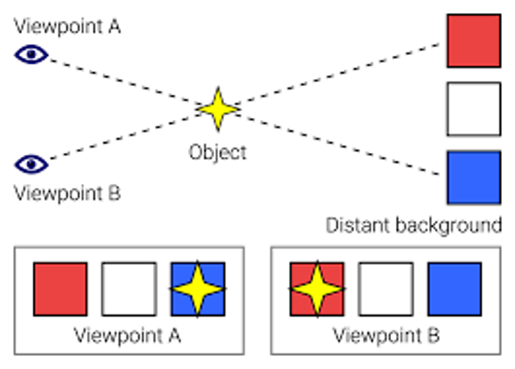
Parallax is caused when 2 different optical systems look at the same object from different angles, which causes artifacts when digitally stitching images together, like “pinched” or “stretched” seams in the image. Circle attempts to correct for this by making the angle of the FOV at the edge of each channel is the same as it’s neighbor, effectively eliminating parallax. Here’s how they do it.
Circle was curious about producing a system that was free of chromatic aberration, both for the sake of controlling performance and achieving a hyperspectral system with extreme field of view through their tiling approach. The only systems absent from color contain only reflective design elements, something Circle is not fully versed in, so we were tasked with investigating it, and all the design hardships that come with it.
End Goal Specifications
| Spec | Goal | Achieved | Pass / Fail | |
| First order | Wavelength | Visible OR Visible & SWIR | Hyperspectral | Pass |
| Core FOV | >20 deg | 32×24 deg | Pass | |
| Extended FOV | 0.5 deg | 0.5 deg | Pass | |
| EFL | 27.04 mm | 27.04 mm | Pass | |
| F/# | > 2.5 | 2.5 | Pass | |
| Performance | MTF | > 30% as built | 40% | Pass |
| Distortion | ≤ 1.5 % | N/A | Pass* | |
| Obscuration ratio | < 10% | 0 | Pass | |
| Relative Illumination | ≥ 0.65 | > 0.99 | Pass | |
| Mechanical | First element Shape | Hex or Pent | Hex or Pent possible | Pass |
| First Element Dimensions | < 500 mm | 160 mm | Pass | |
| # of Reflective Folds | 2 or 3 | 3 | Pass | |
| Elements | Refractive Elements | x | Pass | |
| Reflective Elements | x | x | Pass | |
| Freeform Elements | x | x | Pass | |
| Aspheres / GRIN / DOEs | x | x | Pass |
Starting Design
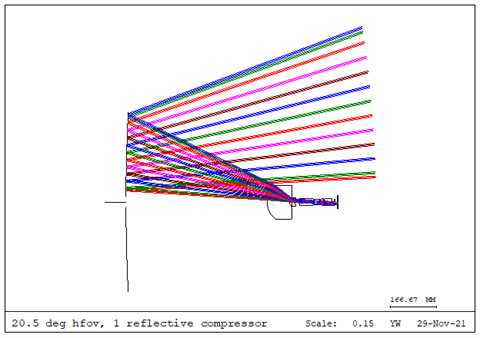
To get this project rolling, Circle provided us with a fully refractive system that is similar in design to the system they already use. We then took that system and converted the front two lenses into a single mirror and optimized it from there, producing this system above. Using this system we then began to replace more and more of the lenses with refractive elements, along with bending the system off axis to unobscure it.
Intermediary Steps
One of the most important decisions we had to make in our design choice was the sign of the power of each of our mirrors. We needed a specific type of entrance pupil while attaining telecentricity and minimal Petzval curvature, so we went with a negative, negative, positive power design. We also realized that with a 3 mirror design we would need one or more freeform surfaces to control both distortion and the overall performance of the lens. Here is an intermediary design, using 2 freeform surfaces and one asphere.
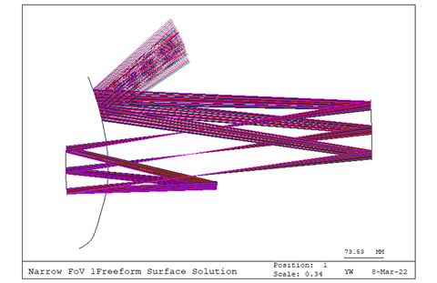
When it comes to positioning the aperture stop and each of the mirrors, we tried to steer the design into a form that would be more easily mountable within a chamber, making sure that the sensor was free enough that it had room to not obscure the system while also allowing for cable management.
Final Design
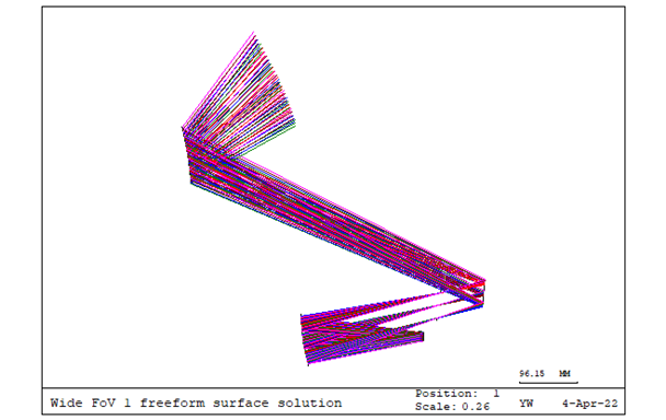
This is the final design we arrived upon given the design path we chose and the initial specifications. This system is fully unobscured, covering over 24 degrees in X and 32 degrees in Y FOV. This design has around 10% distortion while also being diffraction limited, parallax corrected, and hyperspectral. This system makes use of 2 aspheric surfaces and 1 freeform surface. The system also caters to other constraints, such as the placement of the sensor, and it’s able to be tiled together with another identical system. We have been able to tolerance this system (including the freeform) and found that the system is surprisingly manufacturable with as build performance being acceptable given reasonable tolerances.
Future Works
This while this design is not in a state that is ready to be manufactured and sold, it is in a condition where this could be a reasonable starting point for when Circle finds a suitable application for it, being able to start from a working fully reflective parallax corrected telescope. Some future applications could include mounting the camera to a satellite, with the sensor hand picked to capture certain desired wavelengths without heavy redesign. It could be used on drones should the refined design be light enough for flight, or mounted to the roof to a vehicle for a complete view in every direction.