1. Introduction
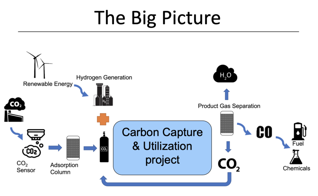
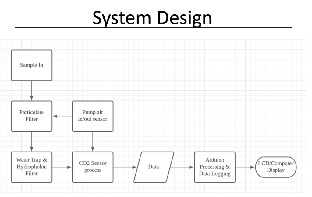
Fig #2: General system design
2. Final Prototype overview
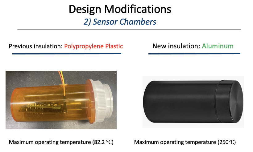
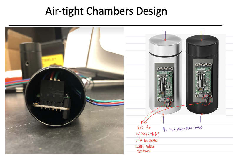
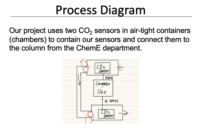
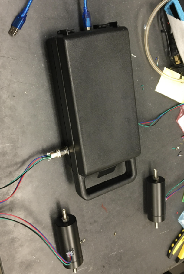
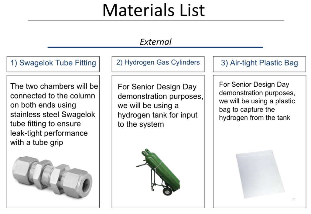
We placed our two sensors into two airtight aluminum chambers connected to the project box
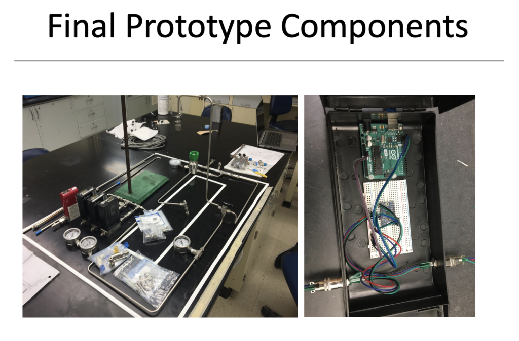
Our project is designed to be integrated with the Carbon Capture Chemical Engineering team’s design (Fig6-Left). Our project box (Fig6-Right) fits most of the equipment of the project (Arduino, I2C multiplexer, and Breadboard) in order to contain loose items and put together the project for easy connection to the two chambers and the computer.
The back of the box connects the Arduino to the computer via a USP connector in order to output the data which includes temperature, CO2, and humidity.
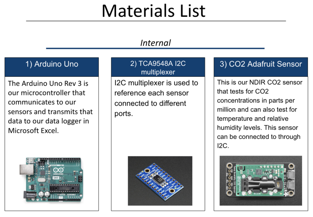
Because both of our sensors use the same address, and we are unable to change the I2C addresses, we decided to use an I2C multiplexer to reference each sensor connected to different ports. This allows us to avoid the conflict of addresses and communicate to each sensor separately.
For this project we had to keep in mind the requirements of the carbon capture system that was being designed by the ChemE senior design team Team Crypto. We acquired the necessary information from the team and mentor Professor Porosoff.
To work more efficiently we divided our team into two parts and worked in parallel. While one group worked on the software of the sensors, the other team worked on the hardware of the setup for the project. This enabled us to complete tasks independent of the other group and there wasn’t a time delay while we waited for the other team to hand off their deliverables.
3. Results and Discussion
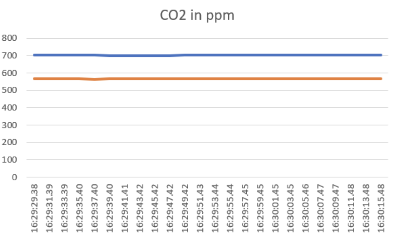
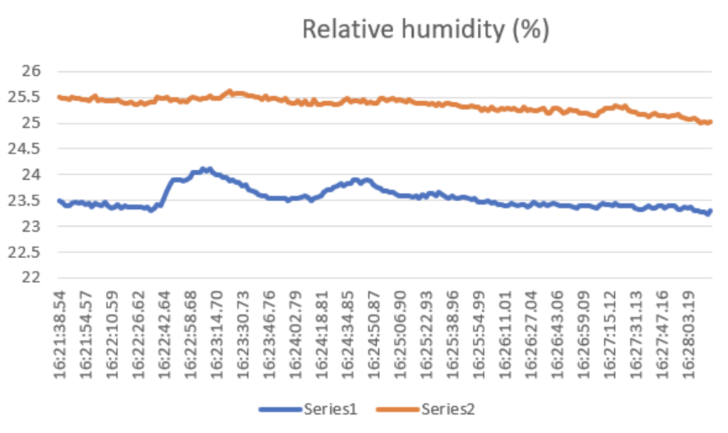
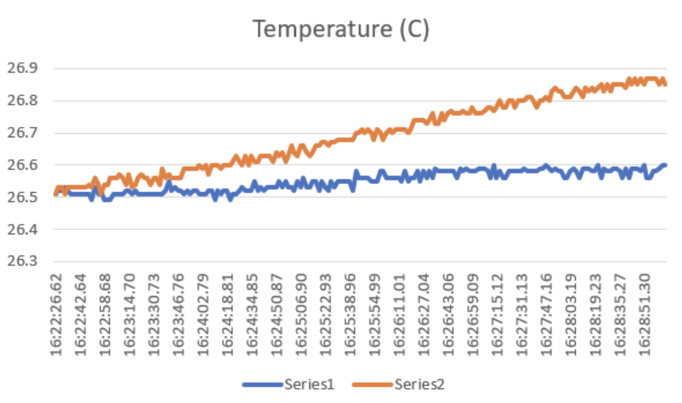

We calibrated our sensors at the Lab led by Professor Porosoff, where we calibrated our sensors to Carbon Dioxide concentration of 375ppm. However, due to the limitation that we are unable to calibrate the sensor to a concentration to lower than 400ppm, we set that concentration (375ppm) to read 400 ppm from our sensor. After which, we still noticed a discrepancy between the two sensor readings of about 40 ppm. Because the main goal of our senior design is to measure the difference between the two sensors, we calibrated one sensor to the other so that they would have the same reading at the same concentration level.
4. Lessons Learned & System Limitations
1) Accounting for project setbacks
I. Late equipment arrival
By finalizing our measurements late as well as finalizing our testing closer to design day, we found that our multiplexer was no longer working after soldering to a protoboard, and we needed to reorder the multiplexer on a short notice.
II. Multiplexer not working
We first noticed that Vin and GND were soldered together and our multiplexer stopped working. However, we found that even after correcting that problem, it was still not working. After a second multiplexer also failed, we think that it could be caused by the heat of the soldering iron that caused our multiplexer to fail. We decided that we would use a breadboard as part of our final product.
2) Prioritizing problems/Working in parallel
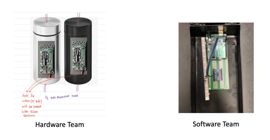
Fig #8: The work to fix problems was divided between members
5. Final Thank You