Team Members

Customer
Dr. David DiStefano, M.D., Year 5 Orthopedic Surgery Resident, University of Rochester Medical Center
Supervisor
Dr. Greg Gdowski, Ph.D., Executive Director, Center for Medical Technology & Innovation
Project Manager Liaison
Ben Hulbert, CMTI, University of Rochester
Project Background
Orthopedic surgery may be required to diagnose or treat joints, bones, or muscles affected by injuries or medical conditions. Bones are often repaired surgically by placing them back into proper position and securing them with plates, screws, or pins, either temporarily until it heals or permanently. Currently, during this type of procedure, orthopedic surgeons use two tools. Initially, plates and screws are secured with a powered device, which provides additional force to initiate the process of inserting the screws. As they progress deeper into the bone and approach the plate, surgeons switch to a manual screwdriver to tighten the screw by hand, providing better control to complete the process. When numerous screws need to be placed, the process of switching back and forth between two types of tools is reported to be a hassle and results in a significant amount of time being spent. From an engineering perspective, this process also introduces variability during surgery and increases the possibility of error.
Problem Statement
Current internal bone plate fixation methods waste time alternating between automatic and manual driving and cause surgeon frustration when relocating the head of the screw. We aim to create a combined automatic/manual device for safe, efficient screw driving in all stages of the fixation process.
Device Design Concept
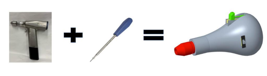
The device aims to combine the capabilities of an electric powered drill and manual screwdriver to create a surgical tool that can operate in both automatic and manual modes.
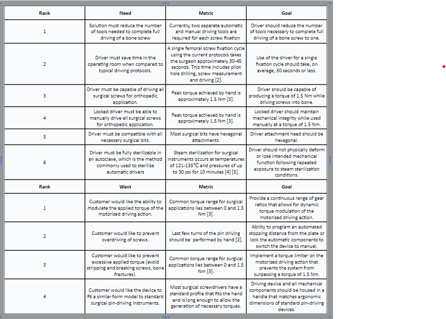
Design Needs and Wants
The below list describes our device needs and wants, along with our corresponding design goals. These needs and wants were developed from research regarding internal fixation surgeries and customer interviews.
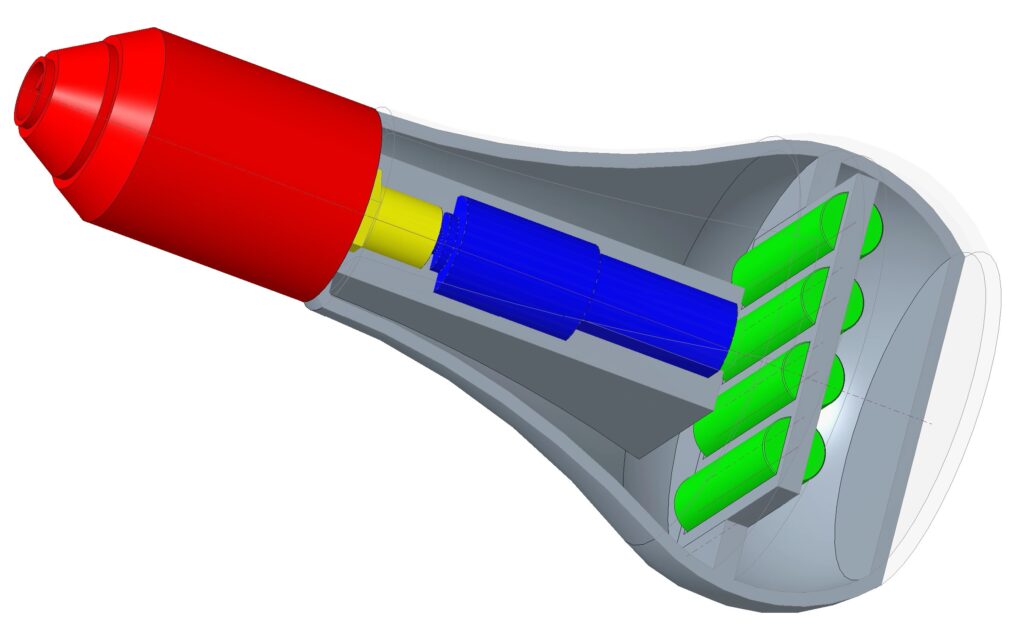
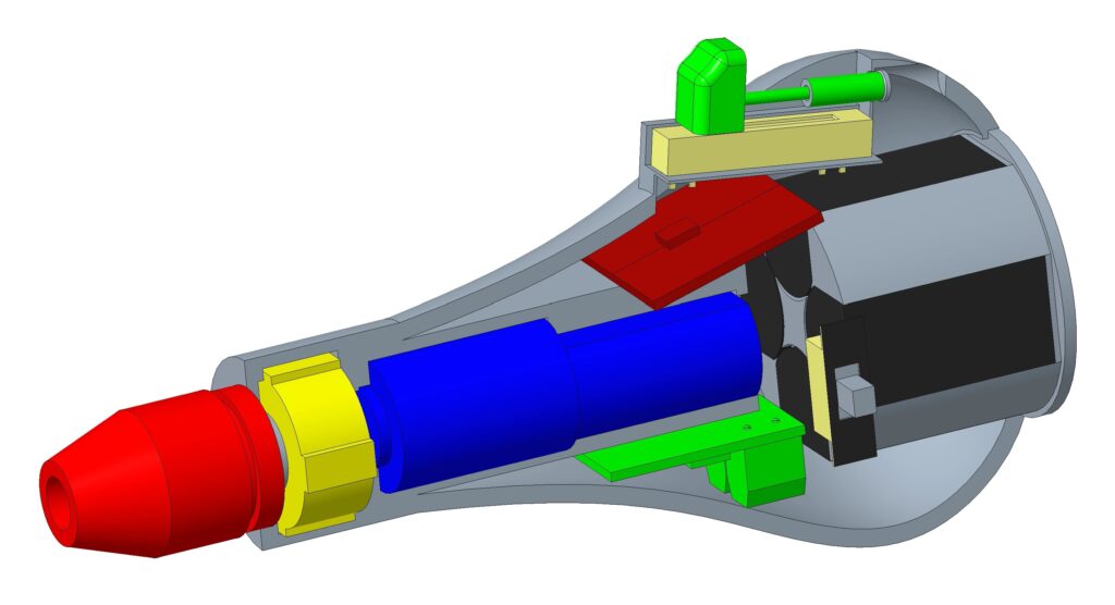
Systems Level Design
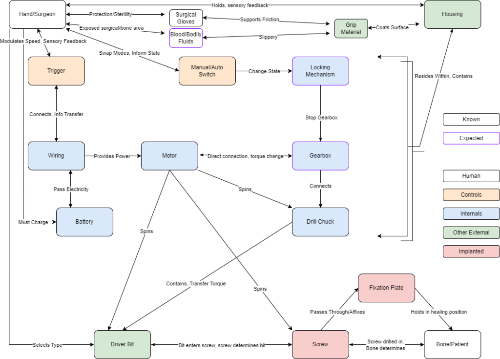
Above is our device’s systems level schematic which details the pathways by which our device allows the surgeon to drive screws into the patient’s bones. This schematic is divided into five categories: Human denoted either the patient or the surgeon, Controls denotes components for the user to make choices, Internals denotes components within the housing that cause rotation, Other External denotes device parts exposed to sterilization, and Implanted denotes anything left semi-permanently in the patient. This design was updated to include concerns that a surgeon may have with gripping the device in the surgical setting. Gloves and blood/bodily fluids were included to take into consideration some of the specific factors affecting the surgeon’s grip on the device.
Prototyping Process
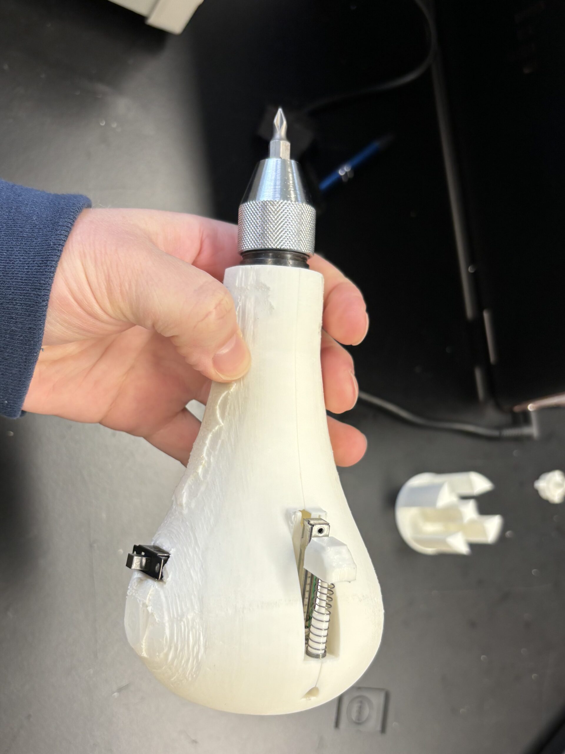
Phase 1: External Housing
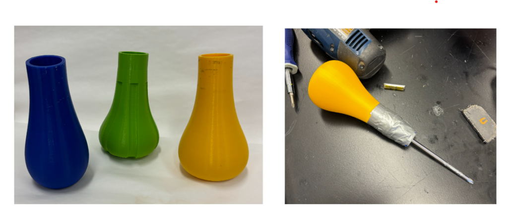
The original design was based off of a pear-shaped screwdriver. The length, width, and radius of curvature were altered based off of the hand feel of the device, while also trying to optimize the amount of space on the inside for internal components.
Phase 2: Basic Internal Components
The first components were the motor, batteries, chuck, and arbor. These were determined to be the basic building blocks for the device. The motor specifications were determined by tearing down a Ryobi power drill and Kobalt electric screwdriver and comparing the different parts. Once specifications were determined and the motor was finalized, an arbor was modeled and designed to fit the motor and chuck together. While doing this, the housing was expanded to make space for a battery pack in the handle.
Phase 3: Specific Internal Components
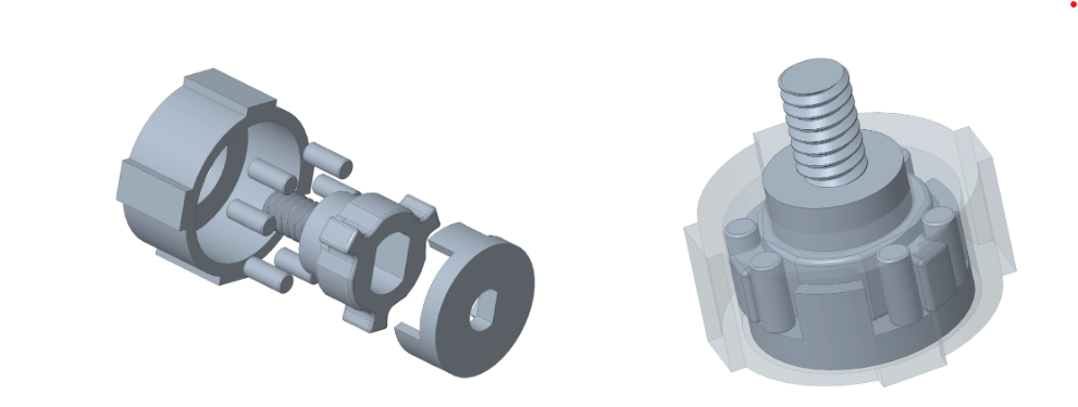
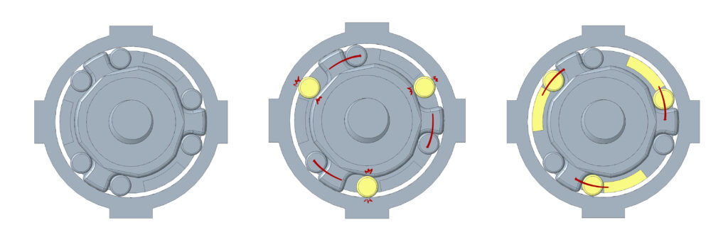
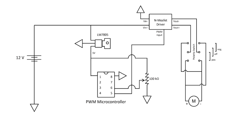
After phase 2, the device worked only as an automatic driver. While attempting to use it manually, the motor would free spin which caused the whole chuck to spin independently of the handle. To prevent this free spinning from occurring, a gearbox was designed to create a locking mechanism. The locking mechanisms worked to lock the motor in place so it will not spin while the driver is being manually used. Control switches were also added: a three-way toggle switch on the side of the housing as a forward, off, and reverse switch, and a sliding potentiometer trigger. This was connected to a pulse width modulation circuit that converted potentiometer position to motor speed using a N-MOSFET driver. Below is a diagram of the circuit:
Phase 4: Putting it together
After phase 3, the device was working, but some of the materials were not withstanding the applied torques, or holding up after continual use. Most of the failures were occurring in the gearbox, with components either stripping down, breaking off, or slipping. This led to a new gearbox design with a metal bolt to screw into the chuck, and metal pins instead of polylactic acid (PLA) plastic ones. The new gearbox was more durable and had fewer slip issues. The battery pack was adjusted to optimize the internal space, and allow easy removal and replacement. A new external housing was printed to account for all of these changes.
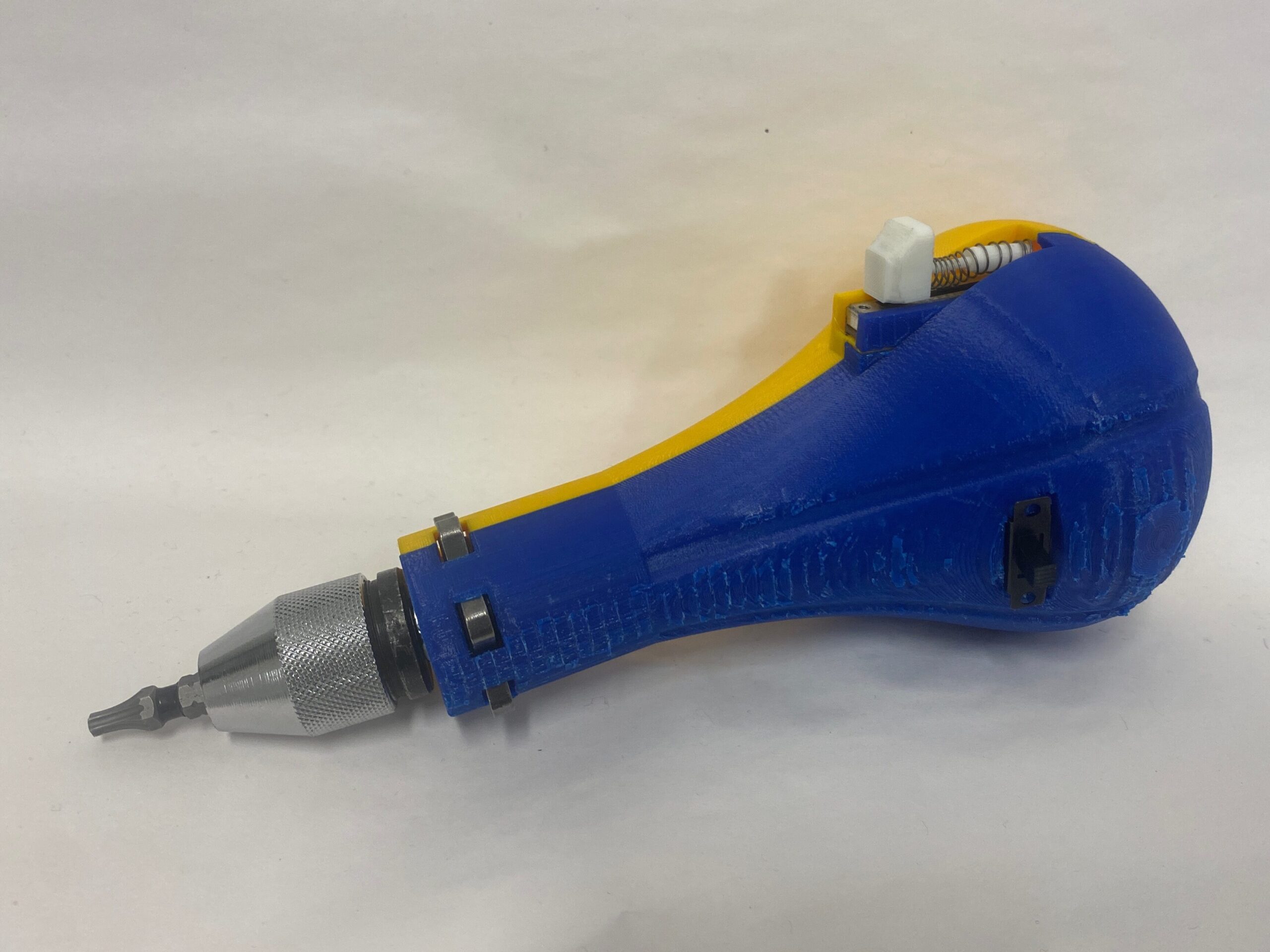
Pictured above is our current final prototype.
Testing
Screw fixation cycle testing was done to see how our device performs compared to the current process of using to separate tools.
Testing Protocols (summarized):
- 8 individuals were tested driving 10 screws into 2 different types of wood (pine and oak) to simulate bone material properties at different ages
- Pilot holes were drilled for each iteration of testing, as they are in orthopedic surgery
- Screws were driven with a baseline automatic driver up to a marked depth, where the user then switched to a manual driver to finish tightening the screw
- Our prototype was tested in the same process, only there was no need to switch tools
- Videos were taken so that the total cycle time could be broken down into individual phases
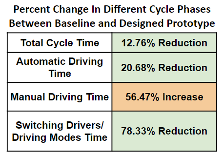
The results of the testing can be seen in the graph and table below:
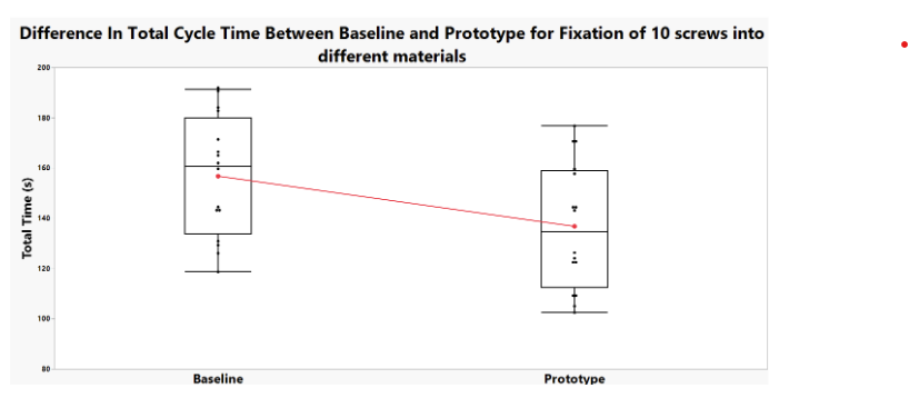
Potential Sources of Error:
- There was some variability in the quality and depth of pilot hole drilling, which had a significant impact on the length of the screw that could be driven into the wood in automatic mode before the torque became too high
- There was significant variability in cycle time between users, as we tested individuals both inside and outside of our group, which may have accounted for comfortability with the testing process and protocols
- The wood samples used had varying material properties in different regions
Future Directions
For future development of this device it would ideally be manufactured using more durable and sterilizable materials than the current prototype. The device’s housing shell would likely transition away from the current 3D printing methods and made via metal injection molding. This part would be made using surgical-grade stainless steel to ensure that the device is able to withstand sterilization procedures. Other components of the device, such as the trigger, would be made from polypropylene or similar plastic to be both durable and autoclave safe.
Future assembly of the device would be different than the current processes used now. Precise soldering would be necessary to ensure that internal components are wired efficiently. Welding would be necessary to permanently close the shell of the device so that surface treatments for surgical-grade quality can be applied. The device would then go through various final quality control processes to ensure no defects before being packaged and given to customers.
The device would also need to undergo more testing in the future. This includes larger samples for the current screw fixation cycle testing completed, as well as further tests to ensure the device does not fail. FDA regulatory processes and preclinical testing would also be required before the device could be put on the market and be cleared for use with patients.
Lastly, future design changes could be made to better accommodate both left and right handed users. Based off the location of the trigger and switches of the current prototype, it is better suited for a right handed surgeon. It may be useful to have two different versions of the device with the triggers and switches flipped, or to redesign the controls to be more ambidextrous.
Acknowledgements
Along with our faculty supervisor, PML, and customer, we would also like to acknowledge and thank Martin (‘Marty’) Gira, Senior Laboratory Engineer, and Dr. Scott Seidman, BME senior design course instructor, for their help and contributions to our project.
References
[1] DiStefano, David., Zoom Meeting, 8 Nov. 2023
[2] DiStefano D.; Auto/Manual combined pin driver for orthopedic surgery pitch video, September 2023, Accessed November 5, 2023.
[3] Ioannou C, Knight M, Daniele L, Flueckiger L, Tan ESL., Effectiveness of the surgical torque limiter: A model comparing drill- and hand-based screw insertion into locking plates, Journal of Orthopaedic Surgery and research., BioMed Central, October 17, 2016, Accessed November 5, 2023. https://josr-online.biomedcentral.com/articles/10.1186/s13018-016-0458-y.
[4] Steam sterilization, Centers for Disease Control and Prevention, September 18, 2016, Accessed November 5, 2023. https://www.cdc.gov/infectioncontrol/guidelines/disinfection/sterilization/steam.html.
[5] Temperature and time requirements in autoclave sterilization. Temperature & Time Requirements For Autoclave | Nev’s Ink | Nev’s Ink. Accessed November 5, 2023.
[6] Orthopaedic Surgery, Cleveland Clinic, Health Library: Treatments & Procedures, February 17, 2023, Accessed December 15, 2023. https://my.clevelandclinic.org/health/treatments/24801-orthopaedic-surgery
[7] “Driver, Surgical, Pin”, Product Classification Database, US Food and Drug Administration, Updated: 29 January 2024. https://www.accessdata.fda.gov/scripts/cdrh/cfdocs/cfPCD/classification.cfm?ID=GFC
[8] “Screwdriver”, Product Classification Database, US Food and Drug Administration, Updated: 29 January 2024. https://www.accessdata.fda.gov/scripts/cdrh/cfdocs/cfpcd/classification.cfm?id=HXX
[9] “Design Control Guidance For Medical Device Manufacturers,” US Food and Drug Administration: Center for Devices and Radiological Health, March 11, 1997.
[10] “ISO standards for Medical Devices: Ultimate List & Overview”, Greenlight Guru, https://www.greenlight.guru/blog/iso-standards
[11] “Evaluation of handle shapes for screwdriving”, Kong Y-K, Lowe BD, Lee S-J, Krieg EF, Applied Ergonomics. 2008;(2):191-198. doi:10.1016/j.apergo.2007.05.003
[12] “Quality System Regulation Labeling Requirements,” US Food and Drug Administration, 31 August 2018. https://www.fda.gov/medical-devices/device-labeling/quality-system-regulation-labeling-requirements
[13] “Code of Federal Regulations: Title 21,” US Food and Drug Administration, Title 21, Volume 8, 17 October 2023. https://www.accessdata.fda.gov/scripts/cdrh/cfdocs/cfcfr/CFRSearch.cfm?fr=820.130#:~:text=820.130%20Device%20packaging.,storage%2C%20handling%2C%20and%20distribution.
[14] “Design Control Guidance For Medical Device Manufacturers,” US Food and Drug Administration: Center for Devices and Radiological Health, March 11, 1997.
[15] Seidman, S. (2024). “FDA Regulations: Using the Waterfall Design Process to Prepare and Organize” [PowerPoint Slides], University of Rochester BME Design Project Blackboard.
[16] Varkey B. (2021). Principles of Clinical Ethics and Their Application to Practice. Medical principles and practice : international journal of the Kuwait University, Health Science Centre, 30(1), 17–28. https://doi.org/10.1159/000509119
[17] StepperOnline. (2022). “DC Gearbox Motor PA22-201213500-G64”. https://www.omc-stepperonline.com/brushed-12v-dc-gear-motor-0-7kg-cm-164rpm-w-64-1-planetary-gearbox-pa22-201213500-g64