Team-Axolotl
- Team Member: Alex Yoo, Charlotte Xu, Cat Milas, Maya Hewitt
- Sponsor: Dr. Brian Cleary
- Mentor: Mark Juba
Overview
The purpose of this project was to identify and optimize factors for a continuous reactor that can be used to prepare aryl amines from nitro arenes using an acid/proton donor system and a heterogeneous palladium catalyst. Running this reaction under continuous conditions is necessary to improve the efficiency of the reaction, as well as cut down on operating costs associated with changing out the current batches at the Eastman Kodak Company. In addition, the scope of this project included running the reaction under a nitrogen purge, which offers a safer alternative than hydrogen gas to produce aryl amines at Kodak. Building a preliminary reactor and running the reaction as a batch process was necessary to first obtain kinetic parameters that carry over to the design of the continuous reactor. Learnings from building and running batch reactions have provided a thorough understanding of the reaction and points of conflict throughout the process. This will allow for the continuation of the project onto the optimization of a continuous reactor in years to come from the solid kinetic foundation established this year.
Background
The production of arylamines from nitroarenes is one of the many fundamental reactions occurring in the Speciality Chemicals Inks and Dispersion division of Kodak. This reaction is used at Kodak to produce couplers, which are photographic materials that when exposed to a developing agent, form a color. In this mechanism, nitroarenes are typically reduced to form arylamines. During a redox reaction, a proton donor system is required to be a source of hydrogen. As a result, efforts toward the development of oxidative procedures for the synthesis of nitroarenes have advanced, leading to the usage of arylamines as reducing agents. Catalytic transfer hydrogenation using ammonium formate as the hydrogen source is shown to be a simple approach for the synthesis of arylamines. Through this mechanism, as shown in Figure 1, it’s hypothesized that the intermediate between the nitroarene compound and palladium hydride, 4-methylformanilide, is formed. Ultimately, ammonium is split from this compound and the new intermediate can participate in the reaction again to form the desired arylamine.
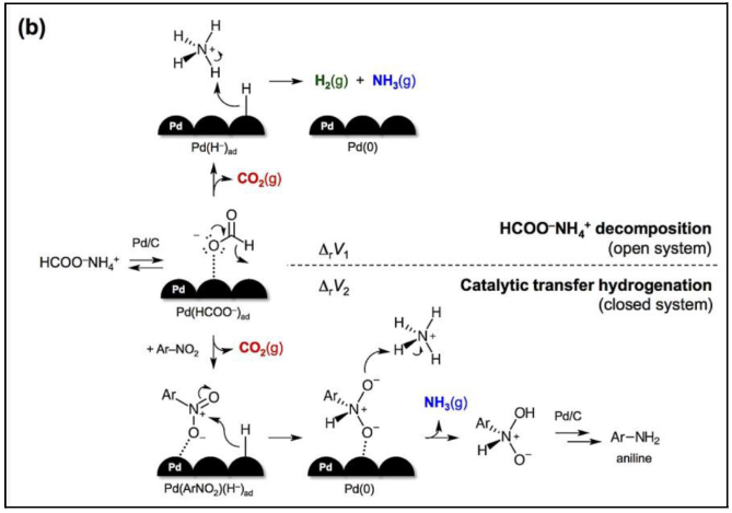
It is important to note that p-nitrotoluene isn’t used at Kodak, as the actual chemicals used to produce arylamines are too expensive to be evaluated in this project. The reduction of p-nitrotoluene to p-toluene mimics the type of reactions (displayed above in Figure 1) currently being employed at Kodak in their production of couplers. As a result, it was provided for the project as a cheaper alternative. Ultimately, the production of p-toluidine in a continuous reactor will be optimized by varying reactor conditions and reagent compositions. The specific reaction utilized in this project is seen in Figure 2 below. At the base level, it involves p-nitrotoluene and 2 moles of ammonium formate acting as reagents. The reaction is run in excess formic acid (HCOOH) and isopropyl alcohol with a palladium on carbon catalyst, yielding the target product, p-toluidine, as well as 2 moles of carbon dioxide and ammonia, and 1 mole of water.

Batch Reactor Design
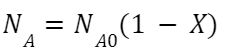
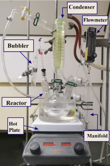
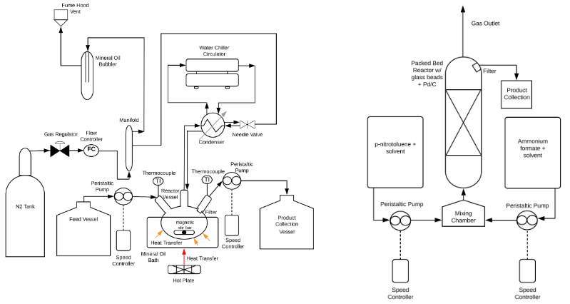
The setup of the batch reactor was shown below in Figure 2. The design and parameters of reaction were optimized. A manifold was added to stabilizing nitrogen flow; The condenser liquid was changed so it can reach lower circulation temperature. All the glassware and tubing connections are secured by hose clamps to prevent gas leaking. The reaction condition is determined by comparing the conversion of the reaction under different conditions. The conversion can be calculated by the equation:
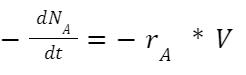
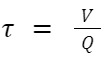
Other parameters including the rate constant, residence time, and the volume of flow reactor, can be calculated by following equations:
The optimized final batch reactor design is shown below in figure 3:
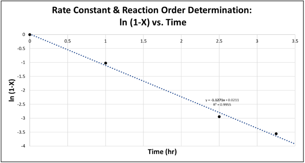
Because the reaction mostly proceeded to the intermediate, 4-methylformanilide, not the product, the conversion was calculated for the amount of intermediate in the product mixture. The conversion from samples collected from the highest-conversion trial was plotted to find the rate of the reaction. The linear relationship of ln(1-X) vs. t shown in Figure 3 below proved the reaction to be pseudo first order as expected in the original hypothesis.
HPLC Analysis
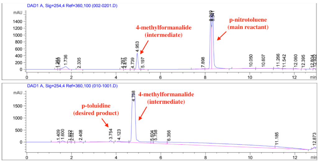
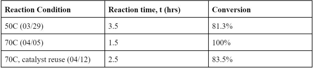
Temperature had a significant effect on the reaction. 70C achieved 100% conversion of p-nitrotoluene at 1.5hr. For 50C, the conversion at 1.5 hr was 80.9% and the reaction didn’t show much progress beyond that. For the 70C trials, the reaction consistently achieved 100% conversion, albeit the difference in reaction time due to issues with temperature maintenance. The catalyst reuse reaction that recycled the catalyst used in the 4/12 trial achieved a conversion of 83.5% at 2.5hrs when the reaction was stopped, meeting the sponsor’s requirement of it being able to achieve conversion above 80%. However, in all cases, most of the p-nitrotoluene was converted into an intermediate, 4-methylformanilide, with less than 5% yield into the desired product, p-toluidine. This is believed to be due to the tripled formate ion concentration from changing the solvent ratios. The formate ion is competing with the intermediate in occupying active sites on the catalyst, hindering the conversion of 4-methylformanilide into p-toluidine.
Troubleshooting
Problem: Maintaining a Single Phase
Initially during the batch reactions, challenges were observed in keeping the reaction in a single phase, which is a critical assumption made in using Equation 2. Even though Kodak runs a similar reaction in batch form and provided molar amounts to use at a 1/10 ratio, this did not account for the differences in reaction conditions that may have caused some materials to fall out of reaction.
Solution:
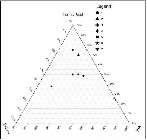
Performed a solvent ratio DoE to ensure optimal molar ratios to keep reaction chemistry constant while maintaining a single liquid phase for the duration of the reaction.
- Lowered temperature of the condenser from 18oC to 7oC in order to reduce the amount of solvent leaving
- Added a manifold to the reaction design to allow a stable Nitrogen blanket to purge the reaction, while allowing minimal solvent evaporation
HPLC Maintenance
- Maintaining constant pressure: Making sure there are no air bubbles in the system; make sure the pump is off when switching solvents. Make sure the pumps are completely submerged in solvent, never run out. Leave HPLC overnight for air to leave the system.
- Leaks: Open 2nd compartment of HPLC (from the top) to see if there is any solvent build-up at the tray. Use the special wrench in the flat desk drawer to tighten any loose connections. Wait to see if pressure stabilizes.
- Consistent solvent composition: Record original amount of ammonium formate used when making solution. 1.8412g per L to make 0.04M aq. Ammonium formate.
Result / Future Work
Future Work
For the continuation of this project, it will be important to push the reaction past the 4-methylformanilide intermediate that the reaction is stalling at. Some suggestions include the following:
- Further explore the ratios of the three solvents—EtOAc, iPA, Formic Acid—while keeping the amount of formic acid constant as it might be responsible for occupying catalyst sites, preventing the nitro reduction.
- Designing a CSTR or PFR as the continuous reactor created in tandem with the project.
- Design a LabVIEW system to automatically calibrate reaction temperature
Initial distinctions between utilizing a CSTR versus a PFR are shown in Table 1; this will be useful for future groups to refer to as a starting point.
Flow Reactor Design
Continuously-Stirred Tank Reactor (CSTR)
Plug Flow Reactor (PFR)
With the rate constant and order of the reaction known, Equation 4 below was used to obtain the rate of the reaction, and Equation 5 was subsequently used to find flow rate and volume parameters to apply to a CSTR.
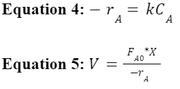
It is recommended for future years to aim for a conversion of at least 60%, which would require a flow rate of 3.77 mL/min for the 300 mL 3 pronged round bottom flask
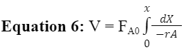
With the rate constant and order of the reaction known, Equation 6 below is being used to find flow rate and volume parameters to apply to a PBR.
Acknowledgement
Team Axolotl would like to thank our sponsor, Dr. Brian Cleary from Kodak, our internal advisor, Professor Mark Juba, and our teaching assistant Thien Hung Nguyen, for their unwavering support and guidance throughout this project and our laboratory advisor Clair Cunningham, for their HPLC mentorship. Additionally, we would like to extend our gratitude to Professor Melodie Lawton, Professor Douglas Kelley, and Jeffrey Lefler for their input and recommendations, and Team Scented Candles (2022) for precise documentation of their reactor design project last year.