Team
- Christopher Harriott
- Nugzari Khalvashi-Sutter
- Nabeel Mukhtar
- Jack Rollman
Mentors
- Dennis Briggs, Danbury Mission Technologies
- Professor Chris Muir
- Mike Pomerantz
- Jim Alkins
- Bill Mildenberger
- Chris Pratt
Abstract
Precision optics need more efficient, smaller machinery for polishing purposes. To achieve this, the team worked with Danbury Mission Technologies to create an optical polisher spindle with a fixed offset and a fixed gear ratio using two shafts with a planetary gear system to generate the desired motion. This was built with a series of requirements and specifications to make sure the customer and producers are in lockstep. The design process included each member creating an independent design and simulation for said design to test its validity. These designs were then compared through a Pugh Matrix, with the highest grade selected. A full set of designs and drawings were created, and the final design was converted into a full-scale CAD model using NX. Mechanical analysis was done to see if the design meets the previously mentioned requirements and specifications – those being: motion analysis, fundamental analysis, fatigue analysis, material selection, bearing analysis, fastener torque analysis, tolerance analysis, contact stress analysis, and housing optimization. The CAD model was then machined to create a functional physical prototype along with a technical report and a theory of operation manual, per the customer’s requested deliverables. The estimation of cost, which included the parts, shop time, and team manufacturing time, was $9,593 and the estimated development time was 582 hours, making labor costs $58,200. The total cost then comes to $67,793.
Problem Definition
Precision optical components often require specialty polishing procedures to achieve desired optical properties. One of the cutting-edge business areas of Danbury Mission Technologies involves manufacturing high-precision optical components for aerospace and defense purposes. Specialty polishing procedures developed at Danbury often require specialized tools that are not readily available on the market.
The goal of this project is to design an interchangeable, fixed offset, fixed gear-ratio eccentric tool spindle for gravity-loaded optical polishing procedures. This spindle will be used to create a specified local motion pattern on an optic and will be attached to a Computer Controlled Optical Surfacing machine to guide global motion along the optic. A successful spindle design will implement a small, lightweight mechanical assembly that can be rapidly exchanged, minimizing manufacturing downtime on the machining floor at Danbury. This will, in effect, improve the production rate and quality of their precision optics.
Requirements, Specifications, and Deliverables
Table 1
Requirements
| Requirement | Description |
|---|---|
| 1 | Lightweight, small, and few components |
| 2 | Compatibility with Danbury Optics Spindle Tools |
| 3 | Ability to attach and detach to the motor output shaft |
The requirements for the system are to be lightweight, small, and have few components, to ensure compatibility with existing Danbury optical spindle tools, and for the spindle to attach and detach to the motor output shaft. To save space on the machining floor at Danbury, the goal is to create a lightweight and small machine. Requirement 2 is included to ensure usability between this system and existing Danbury technologies. Likewise, requirement 3 is added to accommodate for different spindles on the machine’s motor.
Table 2
Specifications
| Specification | Description |
|---|---|
| 1 | Must fit within 16″ height x 6″ diameter space envelope |
| 2 | Must be functional at rotational speeds up to 500 rpm |
| 3 | Must be functional at torques up to 5 Nm |
| 4 | Must be able to change out spindles within 30 minutes |
| 5 | The tool interface must incorporate a size of 3/8″-16 thread to a 1/4″-20 thread |
| 6 | A minimum factor of safety of 5 |
| 7 | Must be usable in a corrosive environment (<3 or >11 pH) |
| 8 | Must withstand up to 10 lbf of downward pressure from gravity-based forces |
| 9 | Fixed offset radius of (0.5 +/- 0.01”) |
| 10 | A fixed gear ratio of eccentric to on-axis rotation (motor output shaft) (40 +/- 5%) |
| 11 | Total system weight of less than 200 lbf |
| 12 | Less than 200 components |
The specifications for the project are for the system to fit within a space envelope, remain functional under varying speeds and forces, not corrode, have a fixed gear ratio and offset, have a specific weight and number of components, specific change-out time, and a singular tool interface. Each of these specifications is measurable and can be tested with a Computer-Aided Design (CAD) inspection, Finite Element Analysis (FEA), or a physical test.
Table 3
Deliverables
| Deliverable | Description |
|---|---|
| 1 | CAD model |
| 2 | Prototype Optical Polisher |
| 3 | Technical Report |
| 4 | Theory of Operation Manual |
Concepts
For the project, each team member generated a concept of one potential design. These concepts included a sketch and a motion analysis, which were used, among other factors, to determine the feasibility of each design.
Concept #1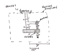
The first concept, shown in Figure 1, uses a shaft attached to the motor, which runs at the lower offset rotational speed. The shaft connects to an offset through a fixed constraint. The offset has a bearing that the secondary shaft revolves around, creating the on-axis rotation. A gearing system drives the main shaft through the offset shaft, the intent of which is to create the desired motion pattern.
When performing a kinematic motion analysis of this design, the desired motion is not created. The analysis uses a revolute joint with a rotation driver at 300 rpm to test the maximum rotational speed case for 500 rpm after the gear, which translates to the shaft through two revolute joints that are coupled as a gear, and a joint that is modeled with a bearing. However, this model creates a single rotational motion, instead of a dual rotation body. The path of movement of a point on the tooltip is shown in Figure 2, compared to the ideal case of motion, shown in Figure 3. No dynamic analysis was performed because the model failed in kinematic analysis. Therefore, this concept is not a contender to dictate motion, although other aspects of the frame and housing proposals are to be considered for the final design.
Concept #2
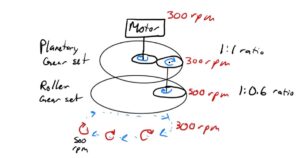
The second concept, shown in Figure 4, consists of a planetary gear set at a 1:1 ratio and a gear roller set at a 0.6:1 ratio. It functions by having a 300-rpm motor spin on the sun gear in the planetary gear set, causing the planetary gear to spin in opposite direction. This gear would have a shaft attached using a bearing to allow free movement. This shaft connects to a smaller gear that would be at a 0.6:1 ratio, causing the gear to move in the opposite direction at the desired 500 rpm. This would allow the entire assembly to spin at 300 rpm clockwise, while the tip spins at 500 rpm counterclockwise.
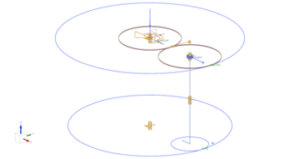
To make the simulation, shown in Figure 5, work as it would in the real world, friction is required on the second (lower) internal ring. Practically, friction will exist in the environment, allowing the roller in the second internal ring gear to rotate at the desired 500 rpm using a bearing that would be in the center of the upper planetary gear. This concept fits all requirements set by the customer and has a positive value in the criteria for the Pugh Matrix table.
Concept #3
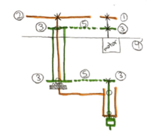
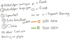
The third concept, shown in Figure 6, incorporates two gears, four sprockets, and two chains to generate and position two different transmissions for the test fixture. This concept uses a motor operating at 500 rpm and one shaft which connects the motor to a sprocket and a gear. The sprocket transfers power to another sprocket through a chain and on a 1:1 ratio. The second sprocket is connected to a third sprocket through a driveshaft which transfers power again through a chain to a fourth sprocket. The fourth sprocket acts as the fixed offset and connects to the tooltip through a shaft. This is highlighted in green as the 500-rpm rotational speed. The gear, either helical or spur, turns a larger gear which reduces the rotation speed of that section at a 1:0.6 ratio. The larger gear is connected to a shaft that extends through the driveshaft and extends out at an “L-shape” with an additional extrusion at the end and converts into housing around the tooltip and fourth sprocket. This is highlighted in orange as the 300-rpm rotational speed by which the tooltip follows.
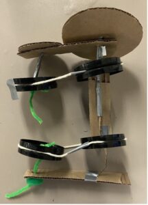
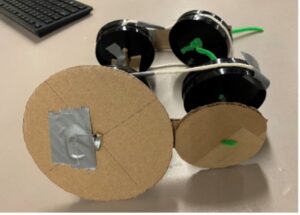
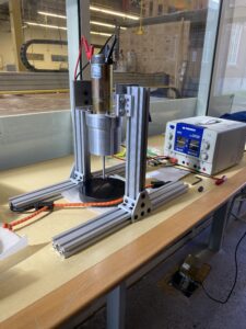
This concept was evaluated as a physical model, shown in Figure 7, which worked to show the two different transmissions generated at the same time. The proof of concept is shown with the existence of the physical model. It is unknown if the rotational speeds can reach 300- and 500 rpm but there are two different transmissions that match the directions of the required product as laid out by Danbury. Due to this, this design is positive in the design matrix and stands as a reasonable option to be the final design.
Concept #4
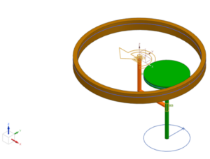
The fourth concept, shown in Figure 8, incorporates a planetary gear set design with one planet. An “L-shaped” arm attached to the motor output shaft rotates in a counterclockwise direction with angular velocity. A planet gear is attached to a second shaft, going through the hole on the “L-shaped” arm. The hole on the “L-shaped” arm is located at some radial distance away from the motor shaft, defining the offset. The position of the hole on the “L-shaped” arm generates a circular pass with an offset from the motor axis during the operation. Planet gear stays in contact with the spindle housing that has an internal gear and therefore rotates in a clockwise direction. The angular velocity of the planet gear is determined based on the difference in pitch diameters of the planet and internal gears.
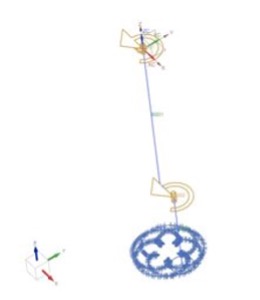
As proof of concept, kinematic analysis has been performed on a simplified CAD model. Figure 8 displays three motion bodies: (1) an “L-shaped” arm, (2) planet gear, and (3) an internal gear, colored in orange, green, and brown, respectively. Body (1) is constrained with a revolute joint and only allows rotation about the Z axis and is modeled with a driver set to 300 rpm. Another revolute joint is placed between (2) and (1) to allow the shaft to rotate freely inside the hole. (3) is fixed in six degrees of freedom. The curve on curve constraint with Lock Slip has been placed between (2) and (3).
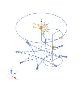
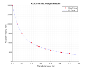
The results of the simulation confirmed the desired motion of the spindle. A trace of the arbitrary point placed on the simulated tooltip is displayed in Figure 11 of Appendix E. Iterations of the design were computed using different diameters of the planet gear to find the corresponding rotation of the tooltip and the relationship between planet diameter and the rotation of the tooltip was calculated to find the desired gear size. This trend is shown in Figure 10.
Concept Selection:
To select the concepts, a Pugh Matrix – shown in Table 1 – was created to evaluate how well the concepts solve the problem. The first category for the Pugh Matrix is the number of major components, evaluating the relative complexity of the design, and aiming to fulfill Requirement 1. Next is the performance in the preliminary analysis, used to determine the ability of these designs to demonstrate success. After, a general reflection on the ability of these designs to meet requirements and specifications in their preliminary form, with or without minor modifications, is considered. Lastly, the ability to machine or acquire parts that will be used in the physical prototype is factored in to evaluate how feasible the machine is to make.
For the Pugh Matrix, the designs are compared to the existing technology at Danbury. From the estimations provided, these machines have a footprint of roughly 30 inches tall by 16 inches in diameter, a payload of approximately 500 lbm, and hundreds more components than the specifications of this project.
Table 4
Pugh Matrix for Concepts
|
|
Baseline |
1 |
2 |
3 |
4 |
|
Number of Major Components |
0 |
+ |
+ |
– |
+ |
|
Preliminary Analysis Performance |
0 |
— |
– |
0 |
+ |
|
Meets Requirements and Specifications |
0 |
0 |
+ |
+ |
+ |
|
Ability to Machine and Acquire Parts |
0 |
+ |
+ |
+ |
+ |
|
Total: |
0 |
0 |
+2 |
+1 |
+4 |
Based on the Pugh Matrix in Table 4, design concept 4 is the best case. This design passes basic kinematic analysis and creates the desired motion patterns while meeting requirements and specifications. Similarly, this design allows room for improvement to improve the function, while still exceeding the baseline design in each category of the Pugh Matrix. While concepts 2 and 3 have positive scores, concept 4 meets and exceeds the goals for the concept stage of the project.
However, aspects of each design have been incorporated into the final model. For instance, the offset plate with the bearing on the eccentric shaft, as described in concept 1, is used to control the rotation mechanism adopted from the final concept 4.
Final Concept
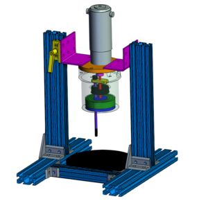
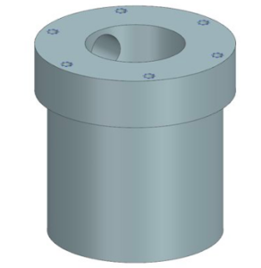
The final concept is based on concept 4, as that best matches the criteria set by the Pugh matrix. A picture of the concept is above. Parts required for this concept are a motor to spin the main shaft, two shafts, features to control the fixed offset, and a planetary gear system used to create a 40% gear reduction.
The internal components are housed inside of an aluminum cylinder, bored with different cross sectional areas to allow for a bearing and a ring gear to fit inside it. The housing is supported by a plate on top which holds the product together with screw inserts and has a groove to locate and support the motor. Beneath the housing, a plate on the bottom is designed to protect the internals from the slurry used when polishing along with glass that would break off the surface. The bottom plate allows for a bearing to be press fit between the plate and the housing. The bottom plate also has a hole for the main shaft, which extends from the motor, through the gear, out the bottom plate, and has a threaded end that is bolted onto the bottom plate. Additionally, the bottom plate has another bearing in it to allow for the rotation of the offset shaft.
To control the fixed offset, a plate will be developed that has have two holes, one for each shaft, milled into it. The main shaft is press fit into it, while the eccentric shaft will be fit into a bearing. This will allow the secondary shaft to move in a different direction than the motor input, enabling the eccentric rotation of the offset shaft for the tool. The second shaft will also hold the planetary gear that will create the specified gear reduction. The bottom bearing’s purpose is to allow free movement of the bottom plate so that it can move with the tool tip.
Mechanical Analysis
Motion Analysis
Specification 10 of the system asks to create a 40% gear reduction from eccentric to on axis rotation. Likewise, Specification 2 indicates that the system must be stable at a maximum rotational speed of 500 rpm. Merging these two specifications, the offset shaft must be spinning at 500 rpm, so the motor shaft should be spinning at a 40% reduction, or 300 rpm. To determine whether the mechanism used in this system could create a motion that meets these specifications, a motion analysis must be conducted. Likewise, the performance of the motion analysis was used to determine the appropriate size of the gears in the system. Due to the size constraints given by Danbury, the size of the gears had to be appropriate to get the desired gear reduction. In the simulations, the gear sizes were varied to test different relationships and different gear ratios, as shown in Fig 10. Once the gear size necessary to create the desired ratio was discovered, the housing was shaped in a manner to allow the gears to be inserted and press fit in. Another set of motion analysis was performed to check if the gear ratio would remain true in the full product’s simulation.
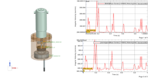
This simulation was conducted using the NX motion analysis package, where a driver was placed on the motor shaft at 300 rpm which has the motion transferred to the shaft coupler, main shaft, offset plate, secondary shaft, and planetary gear. The setup of the analysis is shown in the video below. Additionally, the plots created in NX from the simulation – also shown in Fig. 12 –shows that those motions were possible within the design and fulfils Specification 10, proving the gear ratio.
Fundamental Analysis
One fundamental mechanical issue relates to the torsional stress in the rotating main shaft. The maximum shear stress occurs at the outer radius of the tube, as that is the farthest distance and thus has the most deflection. To calculate the maximum shear stress in a rotating solid tube, find the polar moment of inertia, J, equal to![]()
where c is the outer radius of the cylinder. In this case, c is equal to 1/8”. Solving Eqn. (AA),
![]()
The torsional stress is equal to
![]()
where T is the applied torque. Using specification 3, the maximum torque case is 5 N*m, or 44.25 lbf*in using imperial units. Solving for this use case,![]()
the torsional stress is equal to 14.4 ksi.
Fatigue Analysis
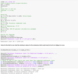
This product will be used for long periods of time in a constant, repetitive motion to spin a tool tip along the surface of an optic for polishing. Therefore, fatigue analysis is conducted to compute the endurance limit of the main steel shaft. The MATLAB code used to perform the fatigue analysis is attached in Figure 13.
The fatigue analysis of a ferrous material is performed using surface modification factors to an initial estimate. The initial estimate, Se’, can be approximated as half of the ultimate stress for ultimate stresses less than 200 ksi. In this case, the ultimate stress of the shaft – made up of 18-8 Stainless Steel – is 70 ksi, so Se’ can be approximated as 35 ksi. The endurance limit, Se, is modified from this initial estimate using
![]()
where each k term is a different modification factor.
The surface condition modification factor, ka, depends on the surface finish by the relationship,
![]() For cold-drawn steel, a is equal to 2.70 ksi, and the exponent b is equal to -0.265, so in this case, ka equates to 0.8758.
For cold-drawn steel, a is equal to 2.70 ksi, and the exponent b is equal to -0.265, so in this case, ka equates to 0.8758.
The size factor, kb, depends on the loading case and the diameter of the shaft. In this case, the shaft is acting in torsion and has a circular diameter of 0.25”, so the corresponding size factor is
![]()
where d is the diameter of the shaft, leading to an interesting result, as the diameter of the shaft is less than 0.3 inches, so the size modification factor is greater than 1, and in this case, computes to 1.0197.
The loading factor, kc, evaluates how the sample is loaded, and is equal to 0.59 because the shaft experiences torsion from the motor. The temperature factor, kd, accounts for how the sample behaves depending on surrounding temperature and is equal to 1 because the system will operate around room temperature (~70 °F). The reliability modification factor, kd, accounts for data scatter. This analysis assumes a 99.99% reliability, to provide additional safety in the calculations and a very conservative estimate for fatigue limits. The last factor, kf, accounts for miscellaneous effects that may lower the fatigue of the system and is set equal to 1.
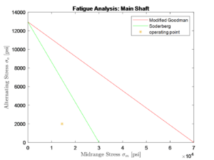
The results of the fatigue analysis are plotted in Figure 14. When observing both failure criteria – Soderberg and Modified Goodman – the fatigue analysis shows that the shaft has an infinite life. For a midrange stress of 14,400 psi – calculated from the fundamental analysis – and an alternating stress of 2000 psi, the operating point is far below the fatigue limit. The loads on the shaft are minimal, as the shaft supports little weight at a relatively slow rotational speed, and fatigue analysis indeed confirms that the shaft would be able to withstand the constant motion applied to it.
Material Selection
In the optical grinding process, a slurry is used as the abrasive. The slurry can range from 3 to 11 in pH but will most often be in an acidic environment. To avoid any liquids getting inside the drivetrain system and affecting the performance of the product, needed to be watertight to avoid liquid getting inside the machinery, economical, and resistant to corrosion and rust. A material that fits these needs is aluminum, so the outer housing is all made of an aluminum cylinder that was machined down to match the design produced in CAD. The gearing in the product was 3D printed using ABS plastic due to its quick production time and accuracy being better than what could be produced at the university out of aluminum or steel. There is discussion that the customer may remove the 3D printed gears and replace them with machined steel gears. Another goal with the material selection was to keep the weight low, as the currently used polishing end is over 200 pounds. The customer recommended aiming for a final weight below 20 lbf. The final product has a weight far below both the 200 lbf specification and the 20 lbf recommendation, where the final product weighs 9.5 lbf.
Bearing Analysis
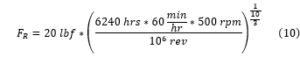
This design incorporates two bearings, a needle bearing and a roller bearing, both of which are aligned to the offset shaft to allow for eccentric rotation. For a bearing, the cataloged load limit will cause failure at 106 revolutions. However, this must be recomputed for the desired lifespan of the shaft. The rating load modification is computed by equating,![]() where FR is the rated load, FD is the desired load, LR is the rated number of revolutions, LD is the desired number of revolutions, and a is an exponential factor, equal to 3 for ball bearings and 10/3 for roller bearings. The computation for the roller bearing on the offset shaft is shown in Figure 14.
where FR is the rated load, FD is the desired load, LR is the rated number of revolutions, LD is the desired number of revolutions, and a is an exponential factor, equal to 3 for ball bearings and 10/3 for roller bearings. The computation for the roller bearing on the offset shaft is shown in Figure 14.
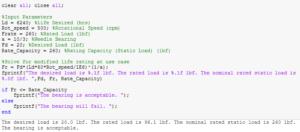
In this case, the rated load correction is to be solved for, the desired load that the shaft will support is 20 lbf, the desired life is 6,240 hours – three 8-hour shifts daily for five days a week over the course of a year – with the rating life of 106 revolutions, at a rotational speed of 500 rpm, Eqn. 9 modifies to,![]() plugging in the actual values for this case, the rating load equates to,
plugging in the actual values for this case, the rating load equates to,
which is equal to 96.1 lbf. The rating load for the bearing in static loading is 260 lbf and in dynamic loading is 360 lbf. Therefore, the adjusted load is less than the cataloged rating, indicating that the bearing will not fail.
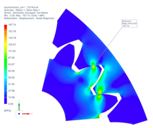
Contact Stress Analysis
In this system, the rotation of the eccentric shaft is achieved with the use of a gear set, consisting of internal and planetary gear. According to the specifications, the spindle must be able to operate at torques up to N-m at the tooltip, with a minimum factor of safety of 5. Contact stress analysis is essential for determining the safety and reliability of the gear system for this application.
To predict failure of gears due to excessive stress, we completed a contact stress analysis on gear teeth, with two material options: Acrylonitrile Butadiene Styrene (ABS) plastic, and AISI 4140 Steel. Manufacturing gears using AISI 4140 Steel for the prototype was not possible at the University of Rochester machine shops, and sourcing a custom set of gears from a third party is costly and time consuming. Due to this, with approval from the project sponsor, we manufactured both gears for the initial prototype using ABS plastic on 3-D printers available on campus. The setup of the Finite Element Model (FEM) used to complete the analysis is displayed in Figure 15, and includes information about gear geometries, meshing, and boundary conditions used to simulate loading and constraints.
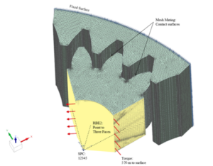
The contact stress analysis on gear teeth was done using Siemens NX CAD software. To simplify the analysis, and reduce computation time, only a portion of both planet and internal gears were used during the analysis. Based on the maximum torque value required to be delivered at the tool, a N-m torque was applied to the inner face of the planet gear in FEM setup. Since planet gear is pressed onto eccentric shaft, and only a portion of the gear is used during the analysis, a Rigid Body Element Type 2 (RBE2) was created to simulate load transfer from the eccentric shaft to the gear without deformations. RBE2 connects 3 faces of the planet gear to the point coincidental with the arc center of the gear. The point was constrained in 5 degrees of freedom allowing revolute motion about the axis of the shaft. The outside surface of the internal gear is fixed in all six degrees of freedom. To improve the accuracy of analysis results, a convergent study was done with incrementally refined mesh size. This was done to confirm that the results of the simulation are not dependent on the mesh size. For smaller mesh sizes (<0.005 in ) however computation time was still significant, and it was decided that it would be impractical to continue the iteration process given the time constraint of this project. In this report, the maximum reported stress values were obtained from a convergence study with 30% or less between iterations. Percent difference values reported in consequent tables are calculated based on:

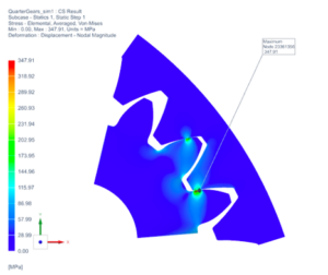
For the set of gears made from AISI 4140 Steel, with a modulus of elasticity of GPa, yield strength of MPa, and ultimate tensile strength of MPa [2], small displacements and linear deformations are assumed. NX Nastran Solution 101: Linear Statics has been used to analyze contact stress on gear teeth. The results of the simulation do not account for dynamic effects that may occur during the operation. Table 5 displays the maximum Von Mises stress values obtained from the simulation. As can be seen in Figure 17, the maximum stress value appears at a point on the planet gear along the sharp contact edge between two gears. It is interesting to note that the stress distribution at other locations is significantly lower. Points of high-stress concentration can lead to increased wear and premature surface damage along the area of contact over time. Furthermore, in the case of premature wear, the deformation of the gear teeth can lead to increased vibrations in the system, which in the case of this application would not be acceptable. In addition, as can be seen from Table 5, maximum stress values fail to converge with reduces mesh size elements. Due to this, the geometry of the gear set was altered in an attempt to eliminate high-stress concentrations.
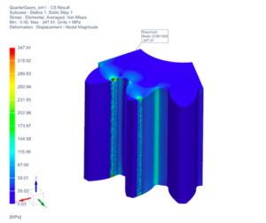
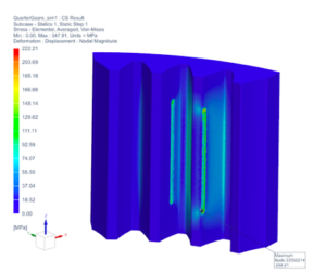
Table 5
Stress Results of AISI 4140 Steel
|
SOL 101: Linear Statics |
|||
|
AISI 4140 Steel |
|||
|
Element Size [in]: |
Max Stress [MPa] |
% Change |
FS |
|
0.050 |
143.50 |
– |
7.11 |
|
0.040 |
170.26 |
17.06% |
5.99 |
|
0.030 |
207.75 |
19.84% |
4.91 |
|
0.020 |
198.27 |
4.67% |
5.14 |
|
0.010 |
273.69 |
31.96% |
3.73 |
|
0.005 |
347.91 |
23.88% |
2.93 |
Taking initial results into consideration, the model setup has been changed and contact stress analysis was repeated. In the revised setup, internal gear geometry was modified to match the height of the planet gear, to eliminate high-stress concentration points along a sharp contact edge between two gears. Model setup can be seen in Figure 19. Table 6 displays the maximum Von Mises stress values obtained from the updated simulation.
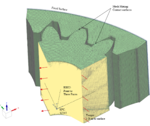
Table 6
Stress Results of AISI 4140 Steel (Updated Geometry)
|
SOL 101: Linear Statics |
|||
|
AISI 4140 Steel |
|||
|
Element Size [in]: |
Max Stress [MPa] |
% Change |
FS |
|
0.060 |
125.99 |
– |
8.10 |
|
0.050 |
124.74 |
1.00% |
8.18 |
|
0.040 |
130.28 |
4.34% |
7.83 |
|
0.030 |
124.89 |
4.22% |
8.17 |
|
0.020 |
134.92 |
7.72% |
7.56 |
|
0.010 |
154.61 |
13.60% |
6.60 |
|
0.009 |
157.32 |
1.74% |
6.48 |
|
0.008 |
166.15 |
5.46% |
6.14 |
|
0.007 |
167.15 |
0.60% |
6.10 |
|
0.006 |
167.74 |
0.35% |
6.08 |
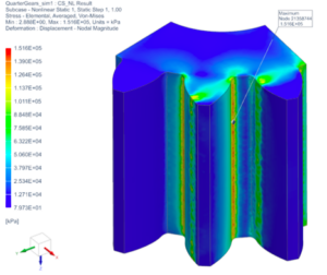
As can be seen from Table 6, for element sizes, the percent difference for maximum stress values between iterations falls below 10%. Upon closer look at the stress distribution, displayed in Figure 6 in Appendix J, it appears that the maximum stress of MPa is reported at a single point along the contact surface on the tooth of the planet gear. The stress distribution in other locations along the tooth appears to be significantly lower and can be estimated to fall in the range between to MPa based on the color scale. Stress concentration points with an updated geometry are not eliminated completely but are reduced noticeably. On the other hand, higher stresses are formed along the fillet radius between gear teeth and the bottom land of the planet gear.
With the assumption of potential failure due to fracture, or tooth breakage, the factor of safety can be computed based on:
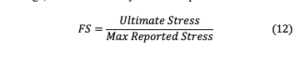
For a final mesh size of 0.006 in and a maximum reported Von Mises stress of 167.74 MPa, the factor of safety of 5 has been calculated and satisfies the minimum requirement of 5. Based on the results of the simulation, it is unlikely that gears prepared from AISI 4140 Steel will fail due to fracture.
A similar contact stress analysis has been completed for the gear set prepared from ABS plastic. Plastics tend to have a low modulus of elasticity and therefore a linear behavior assumption should not be made when performing contact stress analysis. For the set of gears made from ABS plastic, with yield strength of MPa (NX Library), we expect large deformations. NX Nastran Solution 106: Non-Linear Statics has been used to analyze contact stress on gear teeth in this case. Results of the simulation are displayed in Table 7, where maximum Von Mises stress values are reported based on the mesh element size.
Table 7
Stress Results of ABS Plastic
|
SOL 106: Non-Linear Statics |
|||
|
ABS Plastic |
|||
|
Element Size [in]: |
Max Stress [MPa] |
% Change |
FS |
|
0.050 |
125.1 |
– |
0.32 |
|
0.040 |
127.8 |
2.14% |
0.31 |
|
0.030 |
134.3 |
4.96% |
0.30 |
|
0.020 |
141.5 |
5.22% |
0.28 |
|
0.010 |
151.6 |
6.89% |
0.26 |
As can be noticed from the table, maximum stress values exceed the yield strength significantly and continue to grow as mesh element size decreases. Stress distribution of gear teeth can be seen from Figures 21 and 22 in Appendix J. Stress levels along the fillet radius between gear teeth and bottom land of the planet gear are near twice the yield strength, indicating a very high chance of significant plastic deformations and eventually fracture. Since ABS plastic gears are only used in the initial prototype, conducting a convergent contact stress study is not necessary and would be an inefficient allocation of resources.
In conclusion, ABS plastic gear will not be suitable and would not meet the specification requirements of this application. However, due to the low cost and simplicity of manufacturing, ABS plastic gears can be used for the prototype display model. Gears made of AISI 4140 Steel, on the other hand, satisfy and exceed the specification requirement of the ability to operate at torques up to N-m with a minimum factor of safety of 5. Manufacturing of steel gears would be more complex and require more time and funding.
Fastener Torque Analysis
There are 2 types of fasteners that are used, one being a non-permanent fastener and one being a permanent fastener. The non-permanent fasteners join the top plate to the housing and are 6, ¼-20 socket head cap screws.
The proof strength ( of the ¼-20 fasteners is 140 ksi and the stress area ( is 0.0318 inches squared. When including the following equation, the resulting force proof is 30.916 lbf.![]()
When considering that the fasteners are non-permanent, the following equation is used:
![]()
Torque is found by multiplying Fi, the k-value of the type of fastener, and the diameter of the screw. The fastener is non-plated with a black finish, which means it has a k-value of 0.30 and a diameter of 0.25 inches. The final torque of one fastener is 250.425 lb-inches or 28.294 Nm, which exceeds the minimum torque required by the specifications.
![]()
For the threads to engage, there is a minimum length required. Using the variables from above, the minimum length is 0.161 inches.
![]()
Since the fastener has 20 threads per inch, a minimum of 3 threads is required for the fastener to engage.
Tolerance Analysis
This design involves a lot of manufactured components that connect with each other in some way. The top plate, which can be viewed in Figure 23, and the housing, which can be viewed in Figure 24, are joined together by six fasteners with washers. The fasteners are ¼-20 standard sized socket head cap screws and are 1.25 inches in length. The holes in the housing are drilled and threaded to fit a ¼-20 screw and the holes in the top plate are slightly larger, at a diameter of 0.281 inches, to accommodate any egregious errors in accuracy when the holes of the housing were created.
The following is the worst-case tolerance stack-up analysis in both height, Table 8, and width, Table 9, of the major manufactured components of the prototype:
Table 8
Tolerance Results — Height
|
Worst Case Tolerance Analysis – Height |
|||
|
Part Name |
Stack Direction |
Nominal |
Tolerance |
|
Top Plate |
+/- |
0.375 |
0.005 |
|
Housing |
+/- |
4.000 |
0.005 |
Upper Limit: 4.385 inches
Lower Limit: 4.365 inches
Table 9
Tolerance Results — Width
|
Worst Case Tolerance Analysis – Width |
|||
|
Part Name |
Stack Direction |
Nominal |
Tolerance |
|
Housing |
+/- |
3.500 |
0.005 |
|
Bottom Plate |
+/- |
2.8 |
0.02 |
Upper Limit: 6.325 inches
Lower Limit: 6.275 inches
Housing Optimization
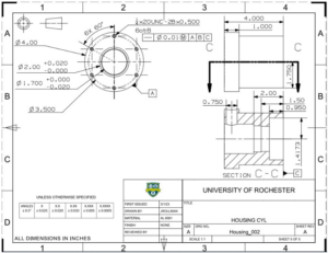
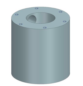
The housing for the product was originally designed to be based on a 4” diameter cylinder which would be hollowed from the center at four different bored diameters. The internal diameter at most is a little more than 2”, meaning the wall’s thickness will be quite large for the purpose. This adds unnecessary weight and will make the product less functional because of it. An image of the pre-optimized housing is in Figure 25. The optimization was done in NX with a 5 lbf torque and a 10 lbf load being applied to the base of the housing. These values are sourced from the specifications given by the customer.
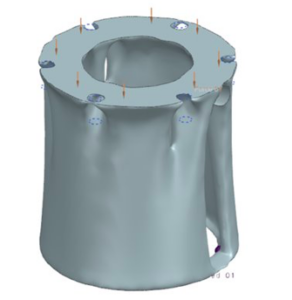
The program then goes through a series of iterations to find at what point the balance between strength and amount material is found. Once the program has run it returns an idealized hollowed out shape that is based on the original housing, as shown in Figure 26 in Appendix L. To make that piece feasible to machine, the diameter for most of the housing was converted to 3.5” in diameter, while the top remained at the original 4” diameter to give enough room to add tapped holes for fasteners. This optimization changed the mass of the housing from 3.424 lbm to 2.56 lbm, saving 0.8654 lbm. The total mass of the product in NX subsequently changed from 10.393 lbm to 9.527 lbm.
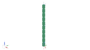
Buckling Analysis
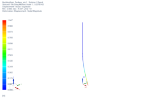
To test specification 8 (must withstand up to 10 lbf of downward pressure from gravity-based forces) a buckling analysis was done to the main shaft. The main shaft is made of AISI SS 304. The set-up, as seen in Figure 28, included two constraints and one force. The first constraint was at the top of the shaft, where X, Y, Z, and RZ were fixed to simulate how the shaft is held by the shaft color to the motor. The second constraint was in the middle to simulate the bearing where X, Y, RX, and RY were fixed. At the bottom, there was a 10 lbf load placed in the -Z direction.
The results., shown in Figure 29, were successful. The shaft had an eigenvalue of 323.7 at a load of 10 lbf, meaning the critical load of the shaft is 3237 lbf, which is far greater than the 10 lbf specification.
Manufacturing
The product has a series of items that require manufacturing using three different materials – aluminum 6061, 18-8 stainless steel and 303 stainless steel, and 3D printed ABS plastic.
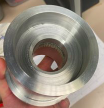
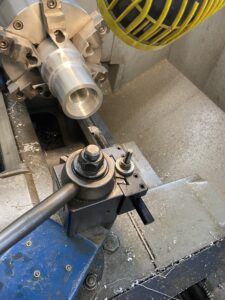
The largest piece to manufacture is the outer housing, shown in Figures 30 and 31 in Appendix M, made from aluminum 6601. A 4.25” diameter cylindrical stock of aluminum was turned on a lathe until the desired shape was produced. The stock had multiple diameters bored out from the center on the inside, along with material removed off the outer diameter to minimize weight of the housing. Aluminum was chosen due to its durability, low cost, low weight, and its ability to resist the acidic environment it will be used in. The housing has a hollow section with multiple regions of different wall thickness to allow for different items to fit in and remain secure, such as the ring gear and the bearing. While the intention was to press fit the ring gear, it would have been risky to press fit the gear inside of the housing, as it would create added complexities to the machining process. Instead, the ring gear was attached to the housing using J-B Weld adhesives. The housing was also taken to a ProtoTRAK to mill six evenly spaced holes, allowing the top plate’s holes to match the top of the housing. These holes were then threaded to allow them to fit socket head cap screws that were attached using helical inserts as fasteners.
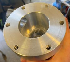
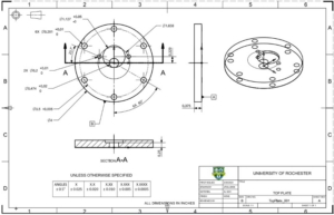
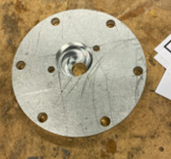
The top plate, shown in Figure 33, was made from a flat plate of aluminum 6061, and the shape along with each of the holes was created using the ProtoTRAK. The ProtoTRAK was used to machine the circular shape of the plate and of the holes. This plate has 6 holes along its outer rim that have fasteners go through them to connect them to the threaded holes in the housing. There is also a larger central hole that the motor shaft goes through and two other holes that screws pass through to fasten the motor to the top plate. Finally, this includes an indent of an offset circle that is used to hold the motor in place by matching the intent on its surface.
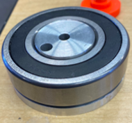
The bottom plate, shown in Figure 34, is made of the same piece of aluminum stock as the rest of the outer housing. This is designed to have a bearing press fit onto the outside of the part and the whole part will rest within the housing. There are three diameters in total, one for the bearing to be press fit on, the second for the bearing to rest on without getting beaten up by the bottom, and the third to allow for the whole product to be waterproof. It contains two through holes, one at the center and one at the 0.5 in offset, to hold both shafts. The main shaft is threaded to support a bolt at the bottom to act as a fastener for the housing. The other shaft is threaded, and a thread adapter is used to secure a female end that a tool can attach to.
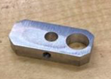
The offset plate is made of a ¼” thick piece of aluminum 6061 that was cut to size using a mill along with making a set of different sized holes. Each hole has a shaft going through it, with the central hole being for the main shaft, and the other hole being for the secondary shaft. The secondary shaft goes through a needle bearing that will be pressed into the plate, so that hole needs to be larger. The offset plate was also given a chamfer on all four corners using a belt sander to make sure it does not interfere with the internals of the housing while in rotation.
The shafts were also faced off on both sides and machined to length. The threaded shaft was given a D-profile to help keep the set screw, from the flexible shaft coupling, in place. They were cut to length using a horizontal bandsaw and the profile was produced using a mill.
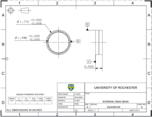
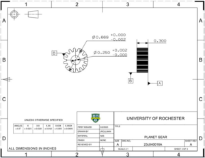
The gears were both 3D printed and their drawings are shown in Figures 38 and 39. Jim Alkins in the Rettner Hall Machine Shop/Fabrication Studio was able to assist with printing the gears. ABS plastic was used as the resolution for the gears was sufficient for smooth contact. The main reason why the gears were 3D printed is because the gears had to be a custom size to obtain the desired gear ratio, so these gears could not be purchased off the shelf. Meanwhile, outsourcing the gears to be machined as a type of steel would have a much longer lead time than the project, as well as siphon away the budget remaining for the project.
Regarding the budget for the project, the team had $1,000 to spend on parts and services. As listed in Table 10, the team spent $893 on parts, and all machining services were performed by team members with some supervision by the surrounding supervisors, so the team stayed under budget for purchases. Accounting for team shop time at a rate of $100 per hour, the time spent manufacturing and assembling the system was 87 hours, which multiplies to a cost of $8,700. The total cost, including purchased parts, is $8,593.
Table 10
Estimation of Cost
|
Item |
Cost |
|
Purchased Parts |
$893 |
|
Purchased Shop Time |
$0 |
|
Team Manufacturing Time ($100/hour) |
$8,700 |
|
Total |
$9,593 |
Table 11
Estimation of Development Time
|
Team Member |
Hours |
Cost |
|
Christopher Harriott |
173 |
$17,300 |
|
Nugzari Khalvashi-Sutter |
121 |
$12,100 |
|
Nabeel Mukhtar |
141 |
$14,100 |
|
Jack Rollman |
147 |
$14,700 |
|
Total: |
582 |
$58,200 |
When this product is passed onto Danbury, their plan is to create many different systems with various fixed offsets and gear ratios. If this product was expanded from 1 system to 1000 systems, it would be hard to scale this without a major simplification of the design of all components and especially the housing. If not, all products would need to be individually made by a machinist, so the lead time and building cost would be large. Likewise, modifying the gear ratio would require new housing shapes and new gear shapes to be made without the ability to easily modify the system. Luckily, this is not a product that currently has the need to be made in that large of quantity and making just a handful more – as intended by Danbury – is still reasonable in terms of time and cost.
Test Plan and Results
|
Specification |
Test |
Result |
|
1 |
CAD Inspection of Dimensions |
Successful |
|
2 |
Finite Element Analysis (First Mode of Vibration) |
Successful |
|
3 |
Finite Element Analysis (Stress, Buckling) |
Successful |
|
4 |
Physical Test: Loading and Unloading System from Stand |
Successful |
|
5 |
Inspection |
Successful |
|
6 |
Incorporated into Design |
Successful |
|
7 |
Choosing materials that can withstand the environment per manufacturer |
Successful |
|
8 |
Finite Element Analysis (Stress, Buckling) |
Successful |
|
9 |
Inspection of CAD and Physical Prototype |
Successful |
|
10 |
Motion Analysis |
Successful |
|
11 |
Weight in CAD, Physical Scale |
Successful |
|
12 |
Count of CAD, Physical Model |
Successful |
Specification 1 passes as the system has roughly a 4” diameter and a height around 10”, as verified by both CAD inspection and measurements of the physical prototype.
As more information on the system became apparent in the design process, specification 11 – specifying a 200 lbf weight limit on the system – was modified to become a 20 lbf limit. This change was initiated by Danbury after the initial list of specifications was finalized and was subsequently approved by the stakeholders of the project. Accounting for usability and ergonomics, minimizing the weight allows for the system to be lifted safely by one person to be installed on the shop floor at Danbury, along with minimizing material costs for the system.
Intellectual Property
For an item to be patentable it needs to be new/novel and not obvious. The designs created for this product are all unique and are not based on previous designs as there are many different methods to grind optics. This is due to every optics company having very different optics they work with and the products they produce, especially when in the precision optics industry. However, since this product is not based on any of the other patented designs due to its wide variety of grinding needs, the product is potentially patentable. The product is also not obvious as it is not simply a different use of an already existing product, instead, it is a new and uniquely created product that was built for a specific purpose.
Societal and Environmental Implications
This product is used for optical polishing internally at Danbury Mission Technologies. The device should increase the efficiency of producing precision optics, minimizing downtime on their service floor, and therefore, increasing the potential output. This could help reduce the costs of precision optics used for space exploration and defense purposes. A benefit of this would be that more technology could be developed with the same level of investment now. These overarching cost reductions show a far-reaching impact of this machine, one more complex than its initial impression.
Regarding ethical concerns, the technology that this product supports will be used in defense systems along with applications in precision optics and aerospace fields. While the goal of this paper is not to take a stance on those fields, it is acknowledged what this technology may be used for. However, much is still unknown about the specifics of how and where this product will be used.
In terms of the product’s environmental impact, the materials used in this are metals – aluminum and steel – along with ABS plastic used in 3D printing. These materials are not harmful for the environment and are recyclable. The material this product produces, glass, is also a recyclable material.
The energy use footprint comes from the motor which drives the spindle. Using more efficient technology to support the inner workings of the spindle mechanism would help improve the environmental impact of the device.
Recommendations For Future Work
The timeframe for this project was roughly four months, spanning from the beginning of January 2023 to the end of April. Had the timeframe allowed for six more months of work, more refinement would allow the system to optimize its performance. A longer project schedule would allow for the completion of tasks that have a longer time frame and the ability to order products with a longer lead time. For instance, the gears on the system needed to be custom designed to allow for the gear ratio to meet specifications. Given the timeframe of the project, the gears were 3D printed out of ABS plastic. However, if a few more months were added to the schedule, that would allow for the gears to be manufactured externally using steel and shipped in time for the conclusion of the product. We recommend that Danbury manufactures gears using a more durable material when applying the prototype.
Another task would be to perform critical analyses of bearings, fatigue, and fasteners before ordering the parts. While these all passed analysis, the ideal way to avoid cost overrun and purchasing redundant parts is to carry out a full analysis of the system before purchasing. However, to account for uncertain lead times and setbacks to the project schedule, purchasing materials began before the final design was completed.
Similarly, the housing could have been made more efficient. The current design incorporates an Aluminum tube with several bored-out holes to house the components that participate in rotation. Even after optimizing the housing shape, there is still potential for improvement to make the housing wall thinner and continue to minimize the weight of the system.
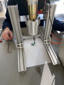
Lastly, another improvement if the project timeline was longer would be to attach the polishing spindle to an existing optical polisher and test on more optics to evaluate the performance of the machine. Currently, the testing setup only tests whether the mechanisms work in a stationary position. If more time was added, it would be useful to test the polished optics for smoothness using optical metrology equipment. While no specification on the quality of the polished optic was given, had the project timeline been longer, that would be a feasible goal for the team. Likewise, it would be ideal to compare this technology to the effectiveness of existing methods to determine how effective this device is.
In-Depth Presentation on Project
Video link to presentation with voice over