Technical Approach
With the process flow diagram (PFD) provided by the Project Sponsor and stakeholder considerations shown on Page 2, the team developed a block flow diagram (BFD) to approach the problem.
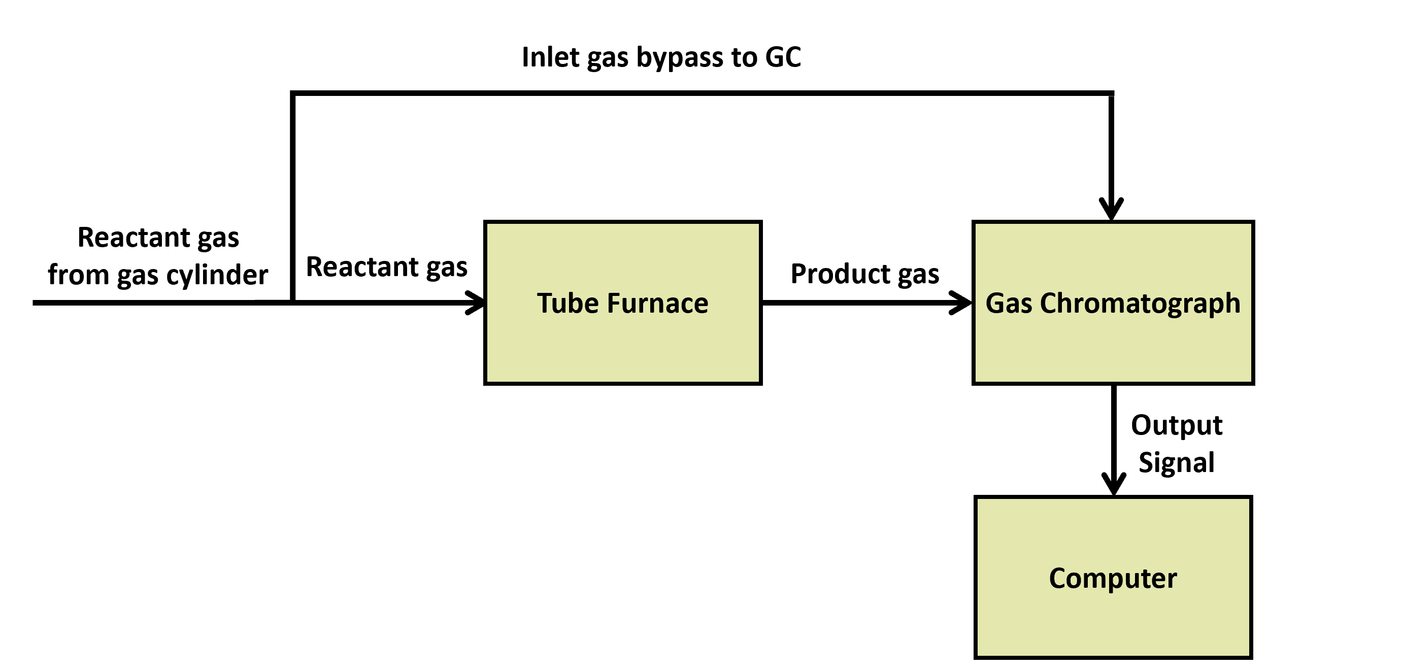
A more detailed version of our approach is shown in Figure 6. Go to Page 4 to see how this drawing ended up in real life!
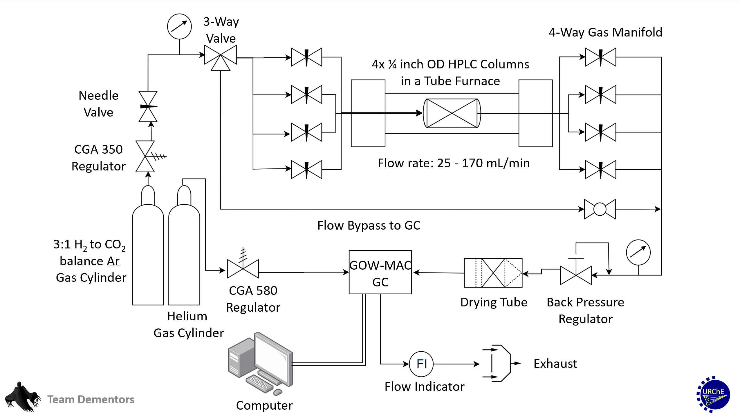
In the following section, some components of the systems will be discussed along with the team’s technical approach to each component.
Gas Chromatograph
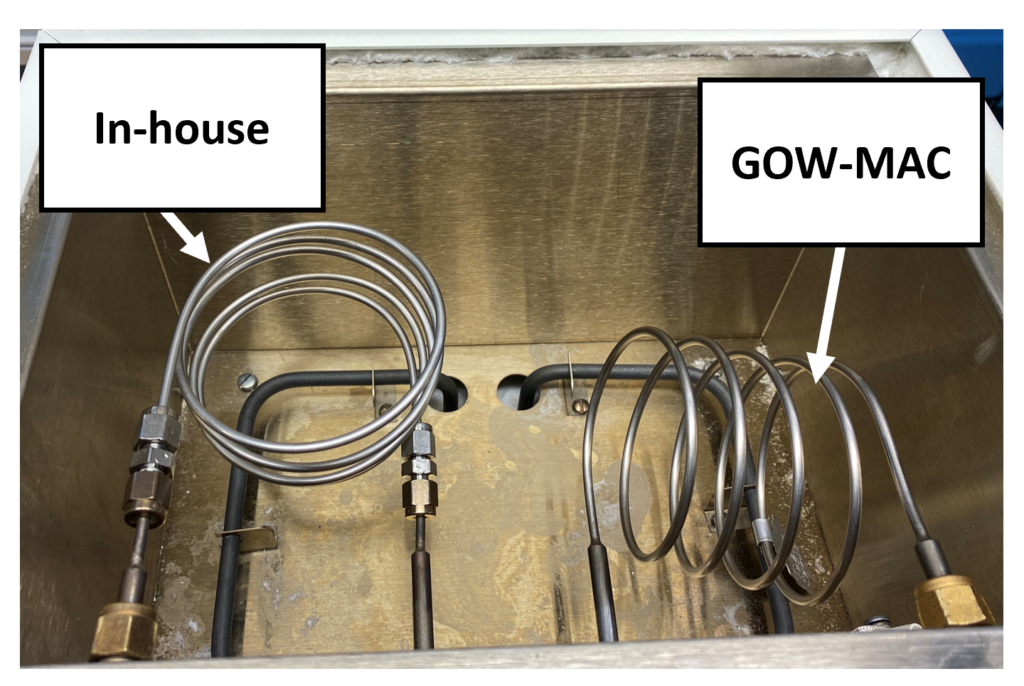
A big task that Team Dementors took on was the repair of an old GOW-MAC gas chromatograph (GC). The major component that was burnt out in the GC was the thermal conductivity detector (TCD) that is essential in the process to identify the reaction products. The following gallery shows some of the steps included in the repair process.
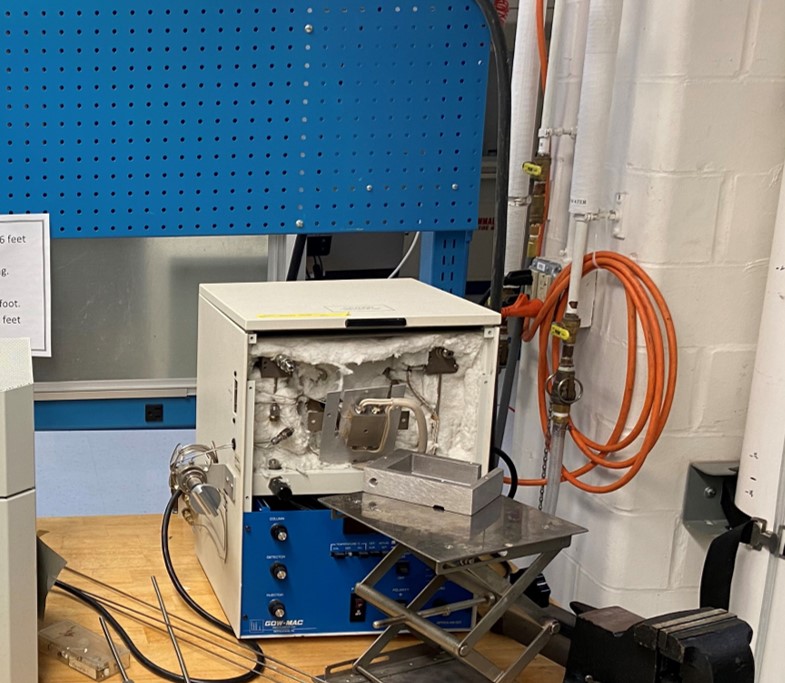
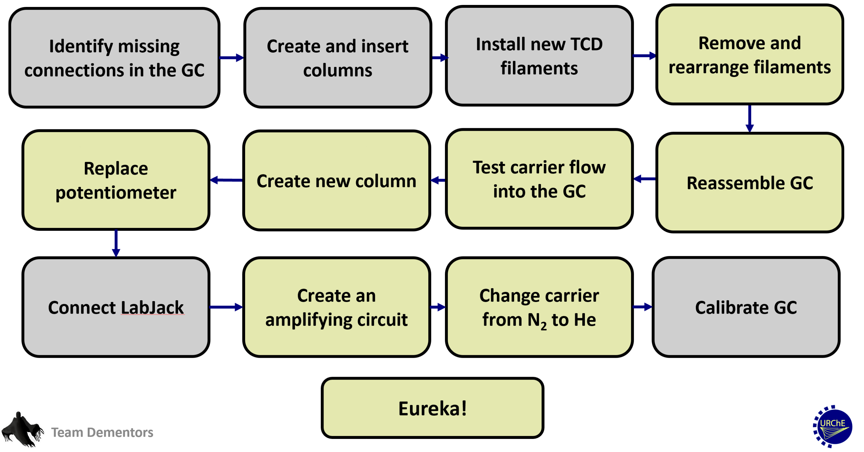
The following flowchart shows the steps taken to repair the GC.
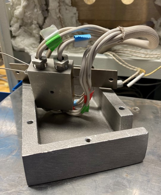
Reactors Scaffold
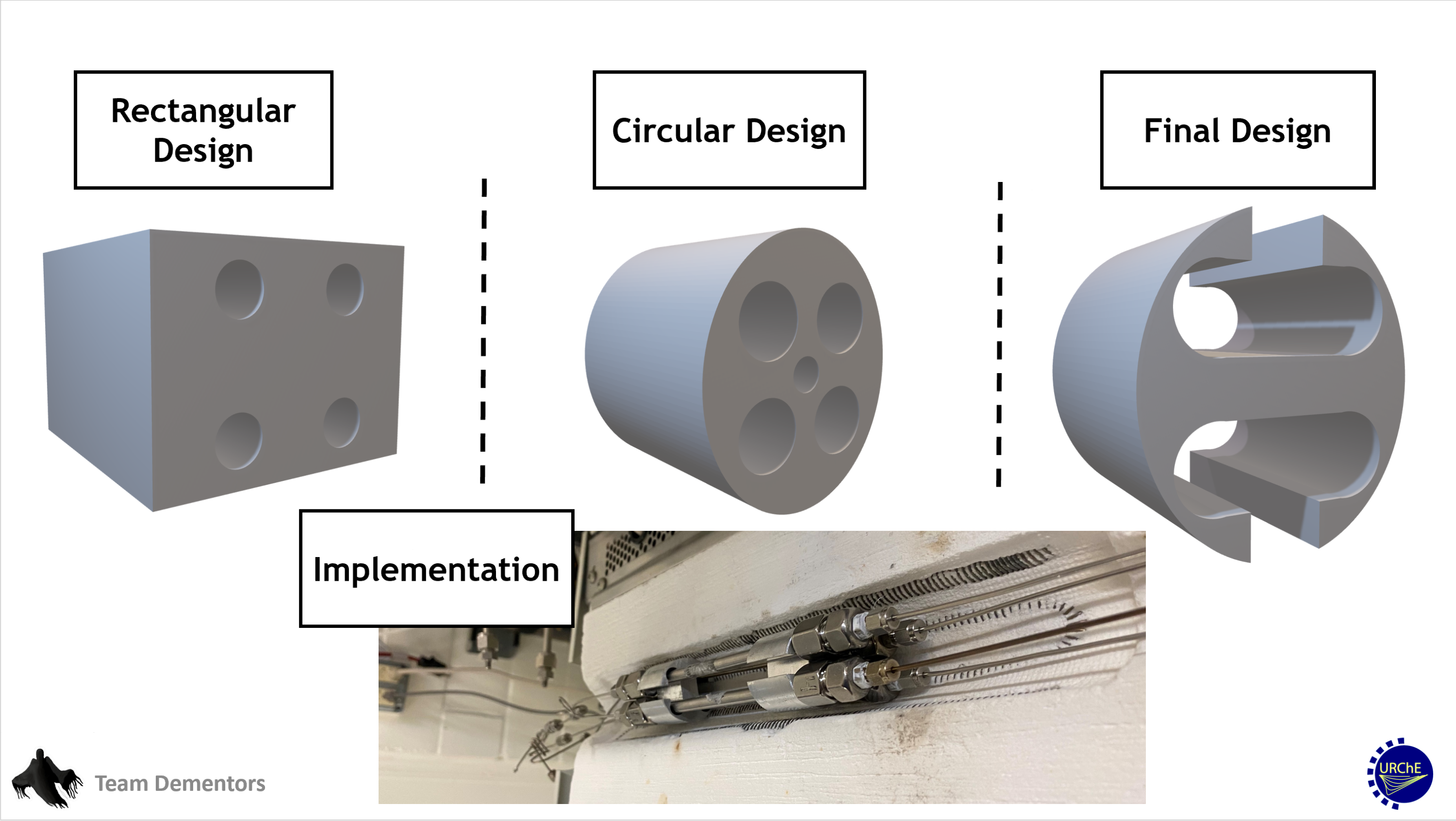
In order to offer rigid support to the reactors inside the tube furnace, the team designed several versions of a reactors scaffold. Figure 11 shows the progression of the scaffold as well as the implementation.
Insulation
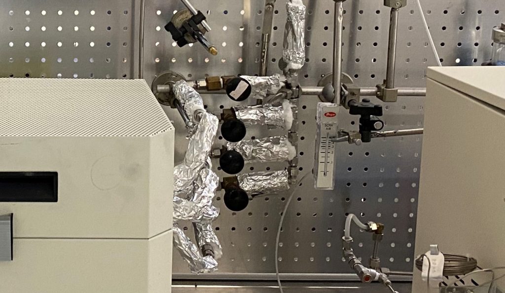
Thermal insulation was added downstream of the reactors. It is composed of mineral wool to reduce heat loss by conduction and aluminum foil to reduce heat loss by convection and radiation. The insulation has two roles:
- Prevent exposed tubing from reaching high temperatures.
- Keep product water in the gaseous phase until it is removed by the drying bed.
Drying Tube
A desiccant bed was included to ensure liquid water does not enter the GC. The bed consists of Drierite (CaSO4), an indicating agent that is blue when unsaturated and pink when at capacity.
The team tested several drying tube options. The final choice shown in Figure 13 was selected for its transparency and high-pressure tolerance.

