Team
- Omolade Fasusi
- Max Fernandez
- Jarrell Aguilar
- Aditi Seshadri
Mentor
Professor Marc Porosoff
Abstract
The concentration of carbon dioxide in the atmosphere continues to rise at an alarming rate. Direct air capture (DAC) is one approach for reducing atmospheric CO2 levels. This project aims to design and build an operational adsorption system to be used in the Porosoff Lab for evaluating DAC sorbents.
Introduction & Background
Problem:
- Increasing carbon dioxide concentrations in the atmosphere has significant implications for climate change.
Solution: Direct Air Capture (DAC) of CO2 from the Atmosphere
- A key requirement for the success of any DAC solution is the design of sorbents that can capture CO2 with high efficiency and release it under controlled conditions, with minimal energy requirements
- Customer Need: A functional lab-scale system that can be used to study the properties of various DAC sorbents
- Project Goal: To design and build a lab-scale adsorption column that can be later used by the Porosoff Lab to study various DAC sorbents.
Temperature-Swing Adsorption (TSA) System
- TSA: sorbents adsorb CO2 at lower temperatures and desorb (release) CO2 at higher temperatures
- TSA Design Implications
- The system needs to be able to reach a wide range of temperatures required to screen temperature-swing DAC sorbents (~25°C – 500°C)
- Reduce the time to heat/cool the column to maximize the number of sorbents that can be screened
- Calcium oxide (CaO) was chosen as a case study for the system
Objectives & Design
Design and build a lab-scale adsorption system for evaluating DAC sorbents
- Design considerations:
- Integrated heating and temperature control
- Control over gas flow rates and pressure
- Ability to monitor the concentration of CO2 leaving the column
- Compact system that fits within approximately one-half of a fume hood (3′ x 3′ x 3′)
- Method to reduce the column cooldown time
- Minimize risk of contact with high-temperature surfaces
- Develop SOPs for operating the system and testing different components
- Key experiments to demonstrate functionality of system
Methods
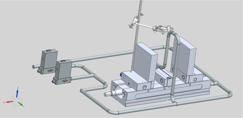
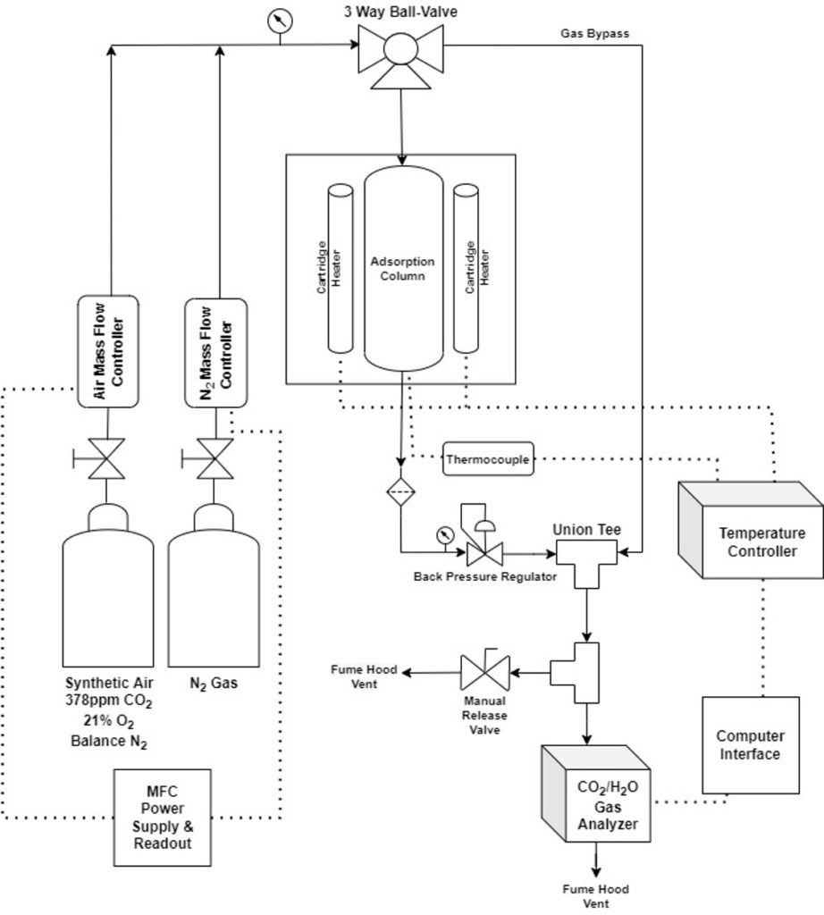
Major Components
- Mass flow controllers allow control of air and N2 flow rates
- Steel plates with insertion heaters for heating the column
- Calcium silicate insulation
- OMEGA Temperature Controller
- Vise with two movable jaws, which allows the insulation panels to be separated from the column for faster cooling
- Adsorption column (4″ long, 0.5″ diameter)
- LI-850 CO2/H2O gas analyzer
Results & Discussion
The lab-scale system was successfully constructed and fit within the allocated space in the Gavett 245 fume hood (Figure 3).
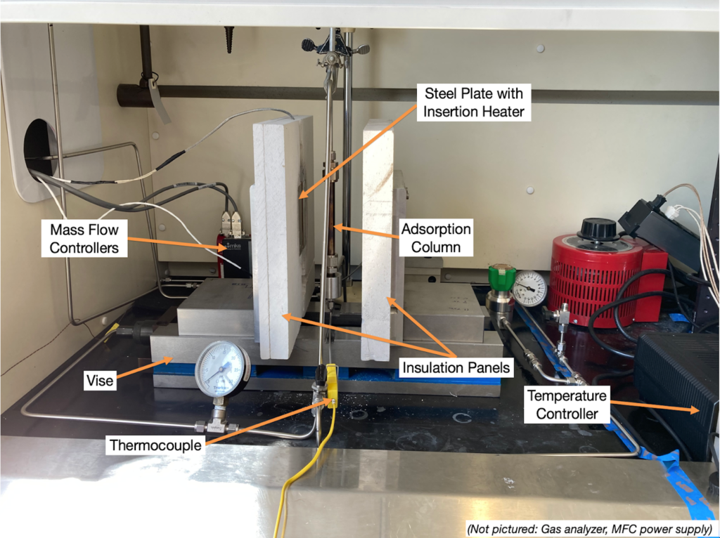
Each component of the system was tested for functionality. Some of the key functionality tests are highlighted below:
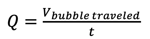
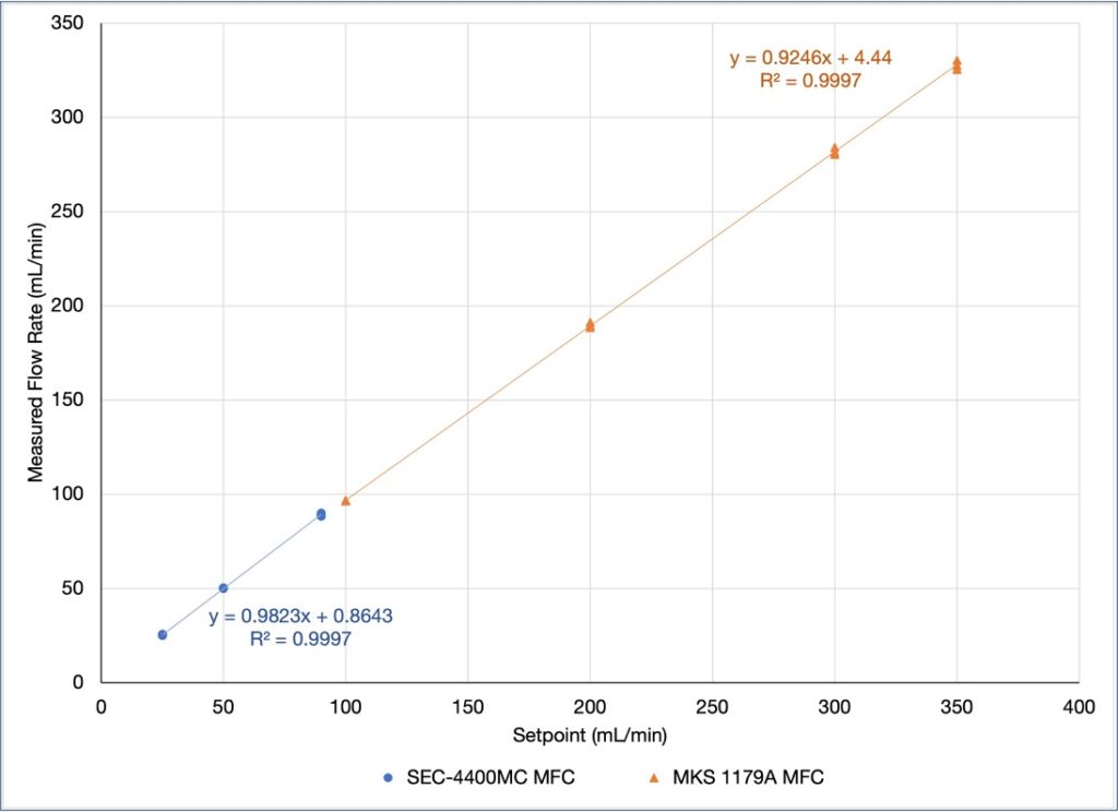
Mass Flow Controllers (MFCs) Functionality
- Used a bubble flow meter to evaluate ability to accurately adjust flow rate with mass flow controllers
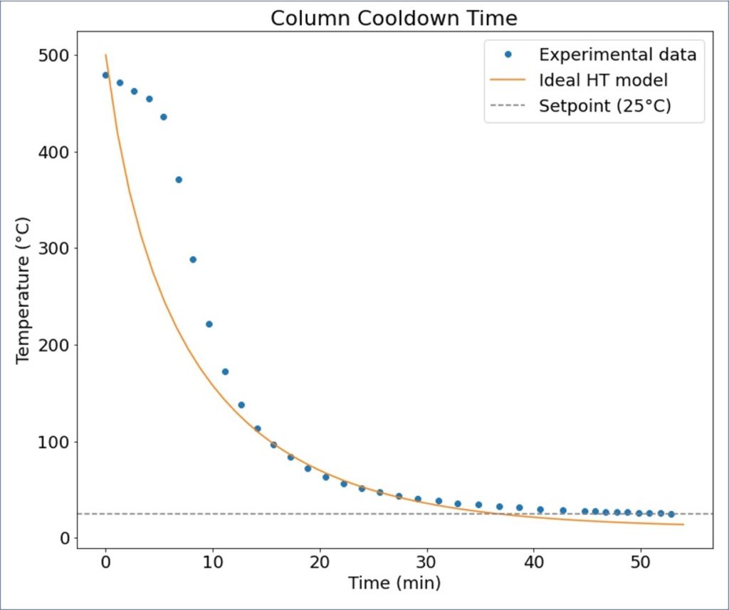
Cooling Capability
- Estimated time required to cool the system down to 25°C (~36 min) was less than that measured (~45 min)
- Possible reason for this difference is that the vise was not opened immediately after the setpoint temperature was changed from 500°C to 25°C.
- When the vise was opened, after ~10 minutes, the rate at which the column was cooling down increased significantly (Figure 5)
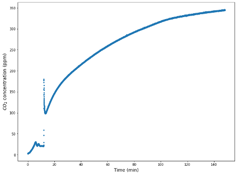
CaO Adsorption
- CaO was chosen due to its availability in lab and the fact that it is a common baseline for CO2 capture sorbents
- CaO reaction:
- CaO (s) + CO2 (g) ⇌ CaCO3 (s)
- An S-shaped breakthrough curve was expected when conducting the CaO adsorption experiment. However, this was not observed and further experimentation is recommended (Figure 6)
Conclusions & Future Work
Conclusions
- Demonstrated the functionality of the system (temperature control, control of gas flow rate, loading sorbent, ability to measure CO2 concentration exiting the column)
- This system can be used to assess the performance of various sorbents for CO2 capture
- Detailed SOPs covering operation of the system as well as testing different components (i.e. gas analyzer, MFCs) were developed
Future Work
- Run additional tests with CaO, varying different parameters (pressure, flow rate, etc.) while keeping the rest of the parameters constant
- In-depth study of different DAC sorbents such as FS-PEI and Zeolite 13X
- Research time delay of system between gas analyzer reading and system changes
- Addition of H2 and CO2 gas lines
- Humidity control
Acknowledgements
Team Crypto would like to give special thanks to our sponsor and advisor, Professor Marc Porosoff, for his guidance and support throughout this project. We would also like to thank Shane Michtavy for his guidance and Jeff Lefler for his help with machining. The team would also like to thank Professor Lawton, Professor Kelley, Professor Juba, Clair Cunningham, Mason Garlatti, and Quinton Dang for their support and technical assistance throughout the semester.