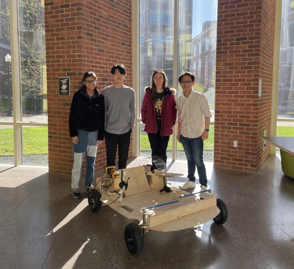
Team Members
- Ryan Choi
- Karla Giron
- Mallorie Plevyak
- Benjamin Smoker
Mentor
Christopher Muir
Abstract
Throughout the semester, a drill powered cart was designed, manufactured, assembled, and tested. This project consisted of multiple subsystems that included drivetrain, steering, ergonomics & braking, and frame. The purpose was to develop a mode of transportation that was not reliant on fossil fuels to be driven. During the development of the cart, there were several components to consider for the project’s success such as identifying the requirements, specifications, and deliverables. For the mechanical analysis of the designs, Siemens NX was used by all subsystems to conduct thorough Finite Element Analysis (FEA) of cart parts. For manufacturing, various tools were used such as the Shop-Bot, mill, lathe, bandsaw, along with many others in the Rettner Machine Shop. After manufacturing, the cart was assembled by integrating all of the different systems into one product. Tests were then performed to determine the success of the initial requirements & specifications that were laid out prior to the start of the project. Although the cart was assembled, through more time, the cart would have been better developed, driving smoother and more efficiently.
Project Description
Requirements
- The cart cannot have two wheels.
- The accelerator, clutch, and brake will all be hand activated
and reachable by the driver. - The clutch will be designed in-house by the team.
- The frame will be made of plywood and cut on the Shop Bot.
- The cart will be operated with a single drill, mounted on the
frame at the rear to transmit power to the wheels. - The cart will have proper safety precautions, such as a
seatbelt, helmet, horn, and guarding, outlined by the sponsor - The cart will be able to complete more than one lapse.
- Each cart team will use the same tires and drill.
- The cart will use Ackerman steering angles.
- The drill will lock and stay on.
Specifications
- The cart cannot have a breaking distance exceeding 15ft.
- The cart must have a turning radius smaller than 10ft.
- The difference in weight of the cart and driver between both teams will not exceed 5lbf.
- The maximum speed of the cart cannot exceed 25 mph.
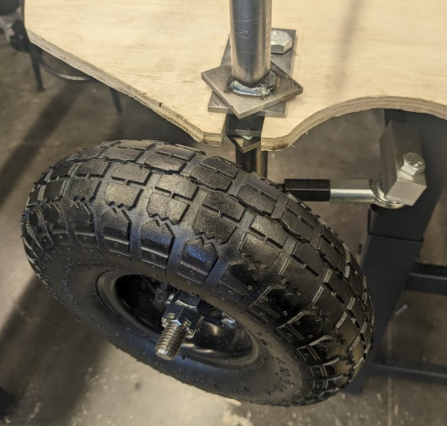
- The diameter of the wheel should be 10 inches.
- The same drill will be used between both teams.
- The thickness of the plywood will be 0.5 inches.
- The driver must be switched every 2 laps during the race.
- The bottom of the frame must be at least 8 in. above the ground.
- The length and width of the cart must be less than 5 ft. and 4 ft. respectively.
Concept Selection
Drivetrain/Clutch: Three different concepts for the drivetrain were considered. Since there was no major improvements on the effectiveness of the other designs, the design chosen was the simplest to implement.
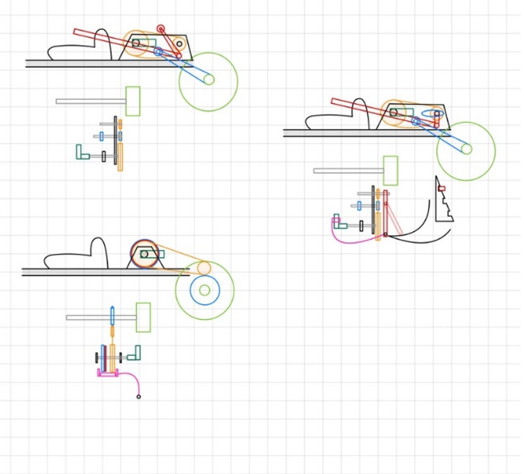
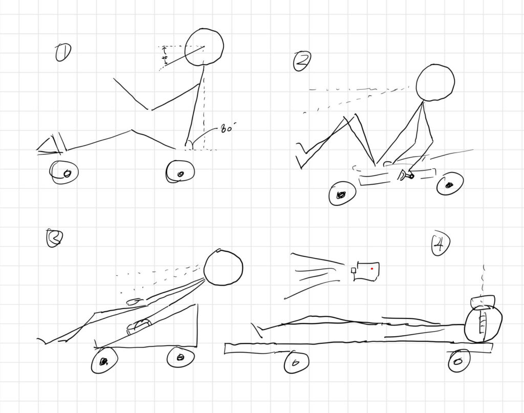
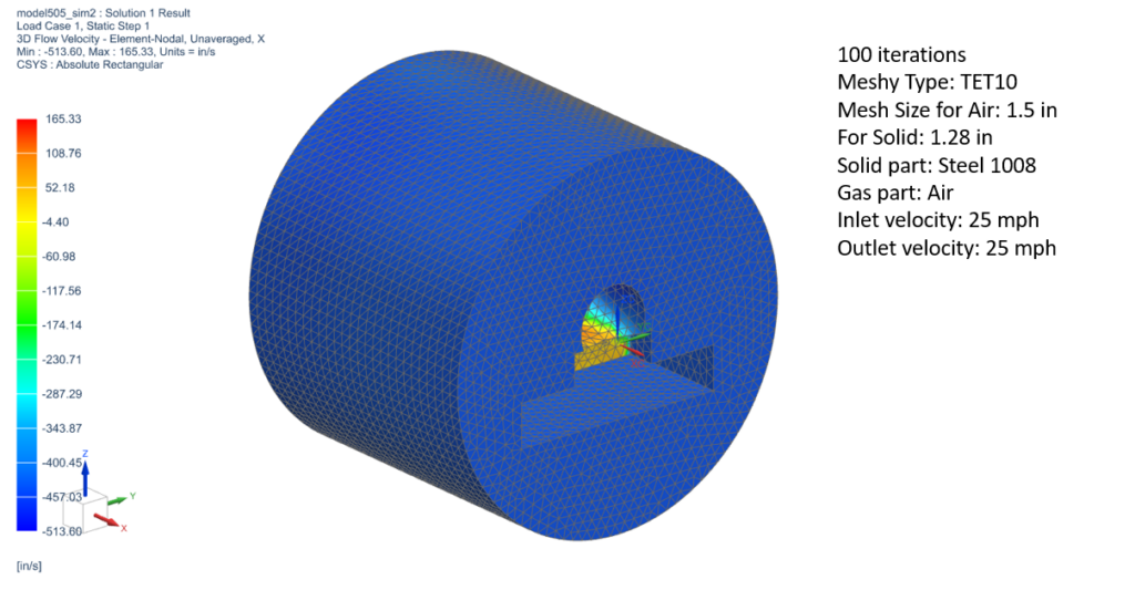
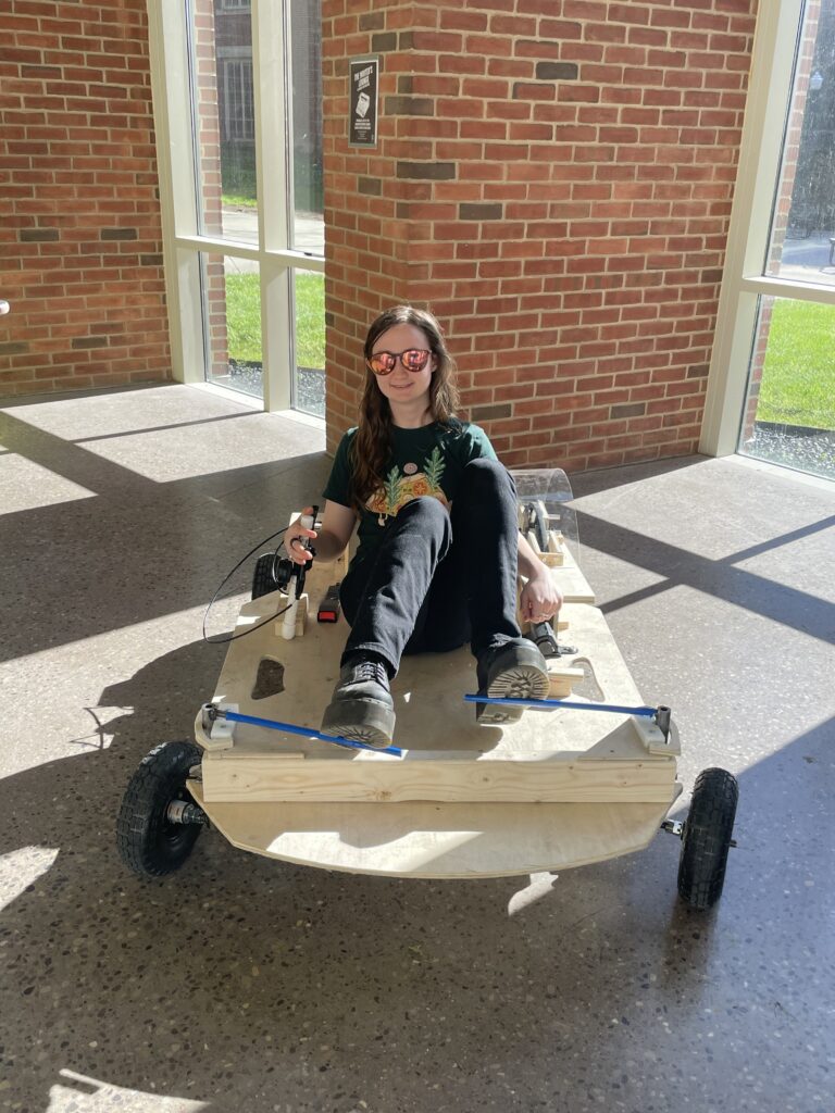
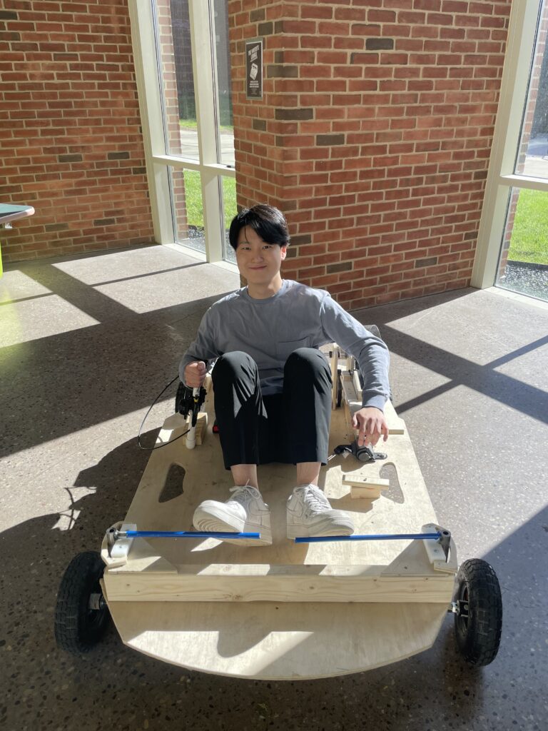
Ergonomics: The flow analysis has been conducted to compare the aerodynamic profiles of different driving positions. The reclined position has shown the highest aerodynamic efficiency according to the result.
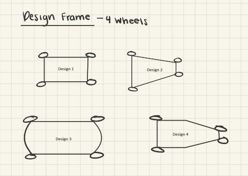
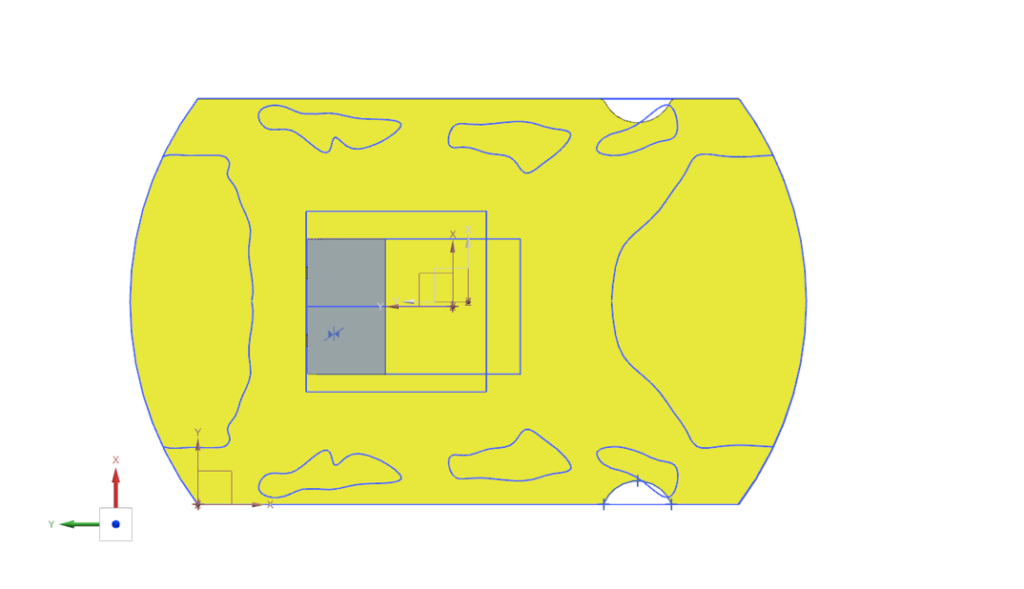
Frame: Four different designes were modeled and analyzed in Siemens NX. Considering that minimizing displacement was cruicial for the fram analysis, the design 3 was chosen to be optimized through topology optimization.
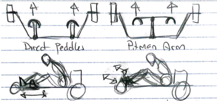
Steering: Direct pedals were easier to produce, easier to attach to frame and had significant improvements in other areas. Due to space considerations, the pedals were moved to the front of the system.
Analysis and Simulation
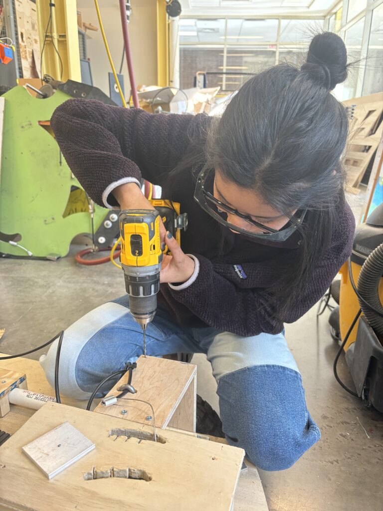
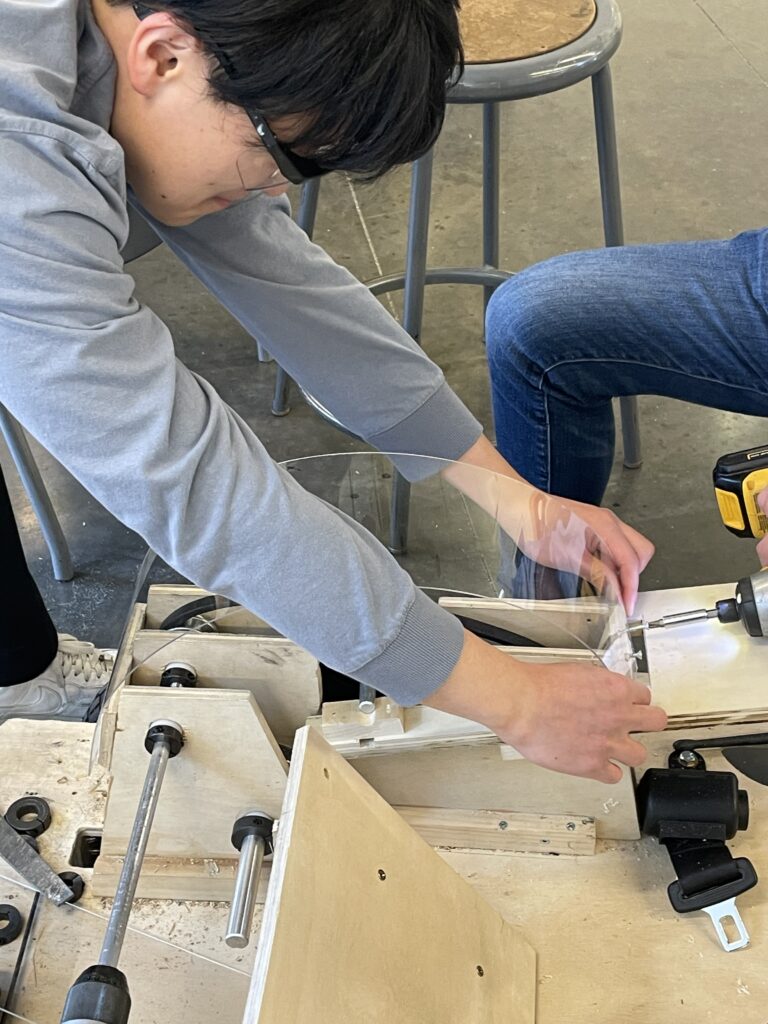
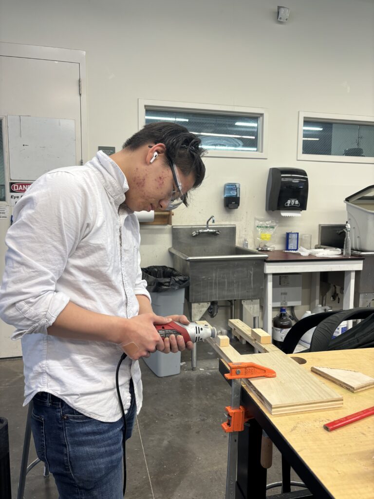
Manufacturing and Testing
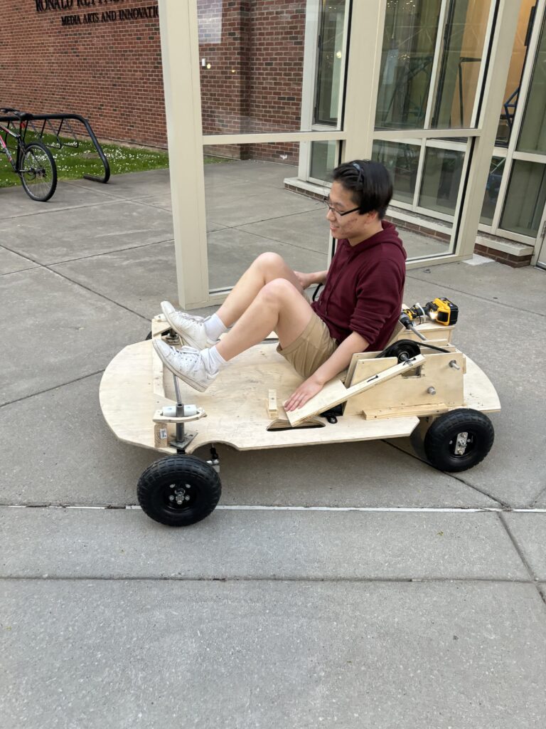
Description
-
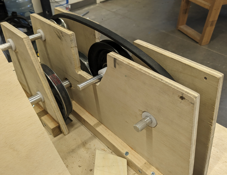
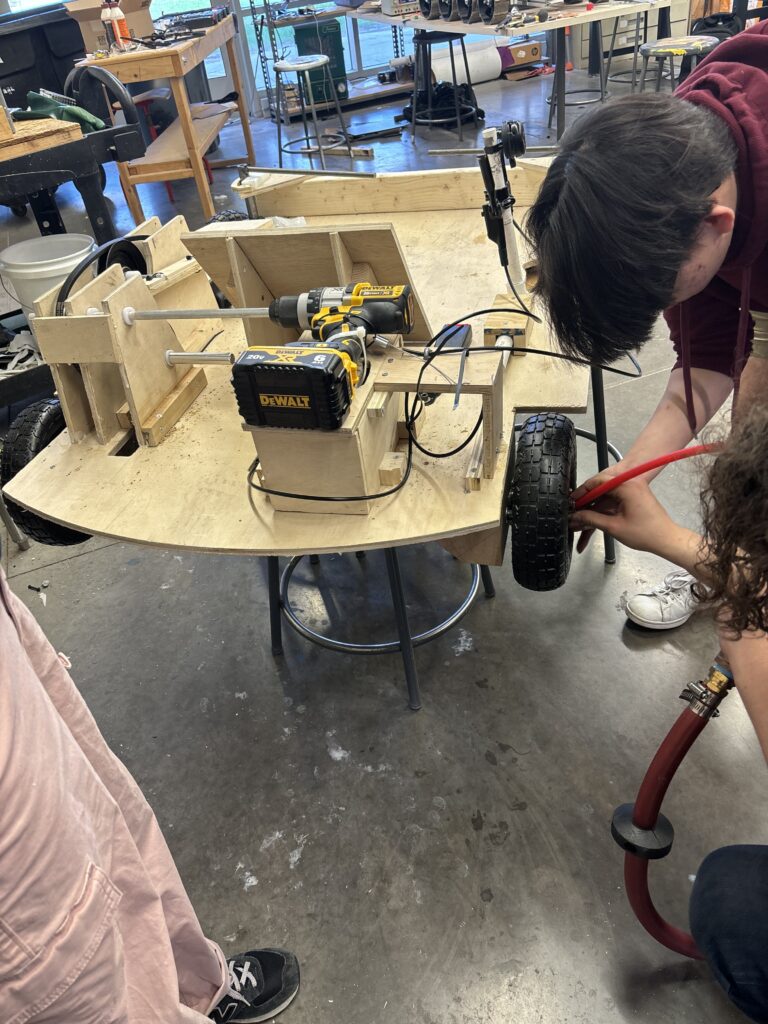
- Drivetrain: The Pulley system is constructed from a set of pulleys connected via a v-belt, connected to milled aluminum rods via keys. This is held together with a wooden frame. The wheels are connected to the rear axle by a second belt and pulley system
-
- Ergonomics: Three key components: Driver Seat, Brake System, Rear Axle Mount. The driver seat was cut out on the shop bot. The rear axle mount was constructed from bearings and wood. The brake system was built using a bike brake mounted on the rear axle shaft
-
- Frame: The manufacturing of the frame was done through NX and the Shop-Bot CNC machine. The CAD of the frame was modeled using NX which consisted of implementing a manufacturing tool for the mill and drill. The STL file was then connected to the Shop-Bot to cut the frame. The weight of the frame was further reduced after performing topology optimization.
-
- Steering: Main steering knuckle constructed out of steel pipe with an outer diameter 1 in and inner diameter ½ inthreaded rod of ½ in for Ackerman and pedal attachment threaded rod of ⅝ in for wheel. They were welded together. Spacers and connective pieces were cut out. Assembly was constructed with bolts and ball joint end caps.
| Specifications Test | Result (Pass/Fail) |
| Turn radius less than 10 ft | Pass |
| Minimizing the weight difference of each team’s driver | Pass |
| The bottom of the frame must be at least 8 in above the ground | Pass |
| Vehicle dimensions | Pass |
| Max speed of 25 mph | Pass |
| Braking distance less than 15 ft | Pass |
| Plywood with 0.5 in thickness | Pass |
| Wheels with 10 in diameter | Pass |
Supplementary Documents