Team Members
Ahmed Abdalla Ihab Youssef Lingyun Huang Samantha Dinhofer
aabdalla@u.rochester.edu iyousse2@u.rochester.edu lhuang21@u.rochester.edu sdinhofe@u.rochester.edu
Mentors
Christopher Muir, Chris Pratt, Mike Pomerantz, Jim Alkins
Problem Description
Normal transportation can be dirty and inefficient. A new form of transportation is wanted for clean, more efficient travel.
Requirement & Specifications
Requirements:
The vehicle will be powered by a single electric drill, each team will use the same drill.
The vehicle body will be made from plywood.
The vehicle can be optimized by each individual team.
The vehicle must have a lap style safety belt and horn for safety.
Pinch points must be guarded and pass inspection by Professor Muir.
Payload will be standardized.
Cart must sustain the weight of the heaviest team member.
The vehicle must utilize a non-traditional steering system.
The vehicle must be able to maneuver the course.
Specifications:
The vehicle cannot exceed 25 mph.
Payloads must be within 5 lbf of each other.
Maximum brake distance of 15 feet at maximum speed.
The vehicle must have more than or less than 4 wheels.
Minimum turn radius of less than 11 ft.
Vehicle dimensions must fit withing 6x4x4 ft envelope.
Nastran Simulation
Concept Selection
Steering System
| Lever one wheel | Lever two wheels | Pedal one wheel | Pedal two wheels | |
| Ease of assembly | + | 0 | + | – |
| Cost | + | 0 | 0 | – |
| Familiarity to user | + | + | – | – |
| Preventing Slippage | + | 0 | + | 0 |
| total | 4 | 1 | 1 | -3 |
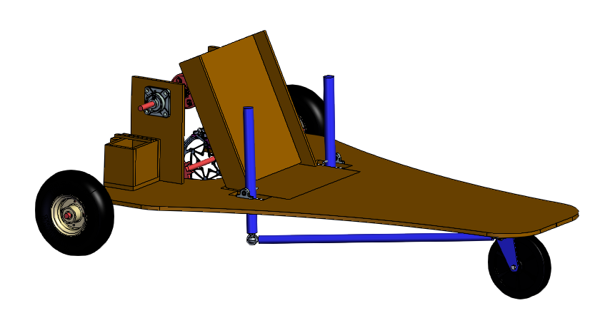
One of the requirements is to steer the cart using an unconventional steering system. This means not using a steering wheel that controls the steering column. Different methods were considered to control steering, including hand levers and pedals. Table 1 shows the Pugh concept selection matrix for possible steering systems. Different options were rated based on manufacturability, cost, and ease of use. Overall, using levers as input is easier to assemble than using pedals. Although steering with 2 wheels could produce tighter turn radius, creating an Ackermann or rack and pinion system is more expensive and harder to manufacture than steering one wheel. Steering using hand levers through one wheel proved to be the most suitable option for steering. As can be seen in Figure 1, The system uses the movement of two levers pushed by the driver’s hands to push and pull two bars that rotate the wheel swivel caster. Steering was decided to be done through the front to separate from the drive train
system applied on the back wheels for ease of assembly and troubleshooting. The cart must have a steering radius of less than 11 ft. The calculation shown in Figure 2 shows the calculation for the steering angle required for the car to clear the course. The steering system was designed using ball joints that can fulfill the required steering angle.
Fig 1
Fig 2
Drivetrain
| Drivetrain Criterion | RWD (Rear Wheel Drive) | FWD (Front Wheel Drive) | AWD (All wheel drive) |
| Practicality | 0 | – | – |
| Ease of Manufacturing | 0 | 0 | – |
| Size | 0 | 0 | – |
| Efficiency | 0 | 0 | + |
| Total | 0 | -1 | -2 |
Table 4 shows the selection matrix for drivetrain mechanism, where RWD, FWD, and AWD were considered. AWD is the most efficient, but the manufacturing and implementation would be complicated in terms of the scope and timeline of project. Rear Wheel Drive (RWD) was selected as it is the most practical and compatible with other systems. Another major deciding factor is that steering is determined to be using the front wheel, so RWD is the best choice overall.
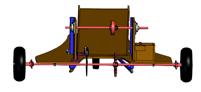
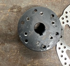
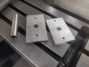
Wheels are to be connected using an aluminum plate fixed to the axle by collars and two connecting threaded rods that connect to the plate in one end and to the wheel on the other.
Body Frame
| Triangle | Rectangle | Others | |
| Ease of cutting | 0 | +1 | -1 |
| Cost | 0 | -1 | 0 |
| Weight | 0 | -1 | -1 |
| Total | Base line | -1 | -2 |
Table 3: Body Frame Selection Matrix
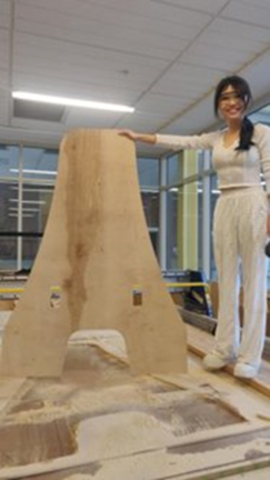
Table 3 refers to the selection matrix of the shape of body frame. To find out the best selection, the cost, ease of cutting, and weight are considered. According to the table, triangle shape is the best choice.
To complete the finite element analysis of body frame, the sitting area of the driver was measured in NX. Specifically, a human body model with driver’s dimensions was placed onto the frame model. Then, draw a rectangle at the human model’s sitting area. To process the FEA of the frame model, a distributed load was assigned to the sitting area. The total load in that area was assumed to be the weight of the driver. Also, the weight of the plywood was embedded into the model analysis.
Braking
Braking:
| Braking Criterion | Conventional/Cable Disk Brake | Hydraulic Disk Brake | Band Brake | Stick in Ground |
| Cost | 0 | + | 0 | – |
| Manufacturability | 0 | 0 | + | + |
| Ease of Assembly | 0 | 0 | – | + |
| Applied Force Required | 0 | + | – | – |
| Total | Baseline | +2 | -1 | 0 |
Table 2 shows the concept selection matrix for the braking system. The criteria considered are cost, manufacturability, ease of assembly, and braking power.
Calculations to determine the braking force needed to stop the cart at its top speed of 25 MPH in 15 feet can be seen in Appendix. This braking force was determined to be 1598.168 N. This is equivalent to 359.281 lbf, thus making the stick in ground concept not feasible. This force can be produced by both the conventional/cable disk brake system and the hydraulic brake system. The main difference between these two systems is reactivity. Ultimately, the hydraulic system was chosen as the pricing is not much different and it is more reactive than the conventional/cable system.
Manufacturing
Results
| Test | Result |
| Maximum Speed < 25mph | 7.5 MPH |
| Braking Distance < 15ft | 11.3 ft |
| Maximum Turning Radius > 11ft | 10 ft |
Recommendations for Future Works
If more time were allotted to work on this project, we would suggest that a more comprehensive NX design and analysis be completed before beginning manufacturing in order to better optimize the design and avoid flaws that might be discovered post-manufacturing without this analysis. Further, a more detailed design would allow the team to know what parts should be ordered early in the design process which could reduce the difficulty caused by shipping delays.
Project Report
Acknowledgements
Drill-Cart Bravo would like to thank our sponsor, Professor Muir, and our TA, Jamie, for their support and guidance over the course of this project. We would also like to thank Chris Pratt, Jim Alkins, Bill Mildenberger, and Peter Miklavcic for providing their expert knowledge and materials. Finally, we would like to thank the other drill-cart teams for pushing us to create the best possible product.