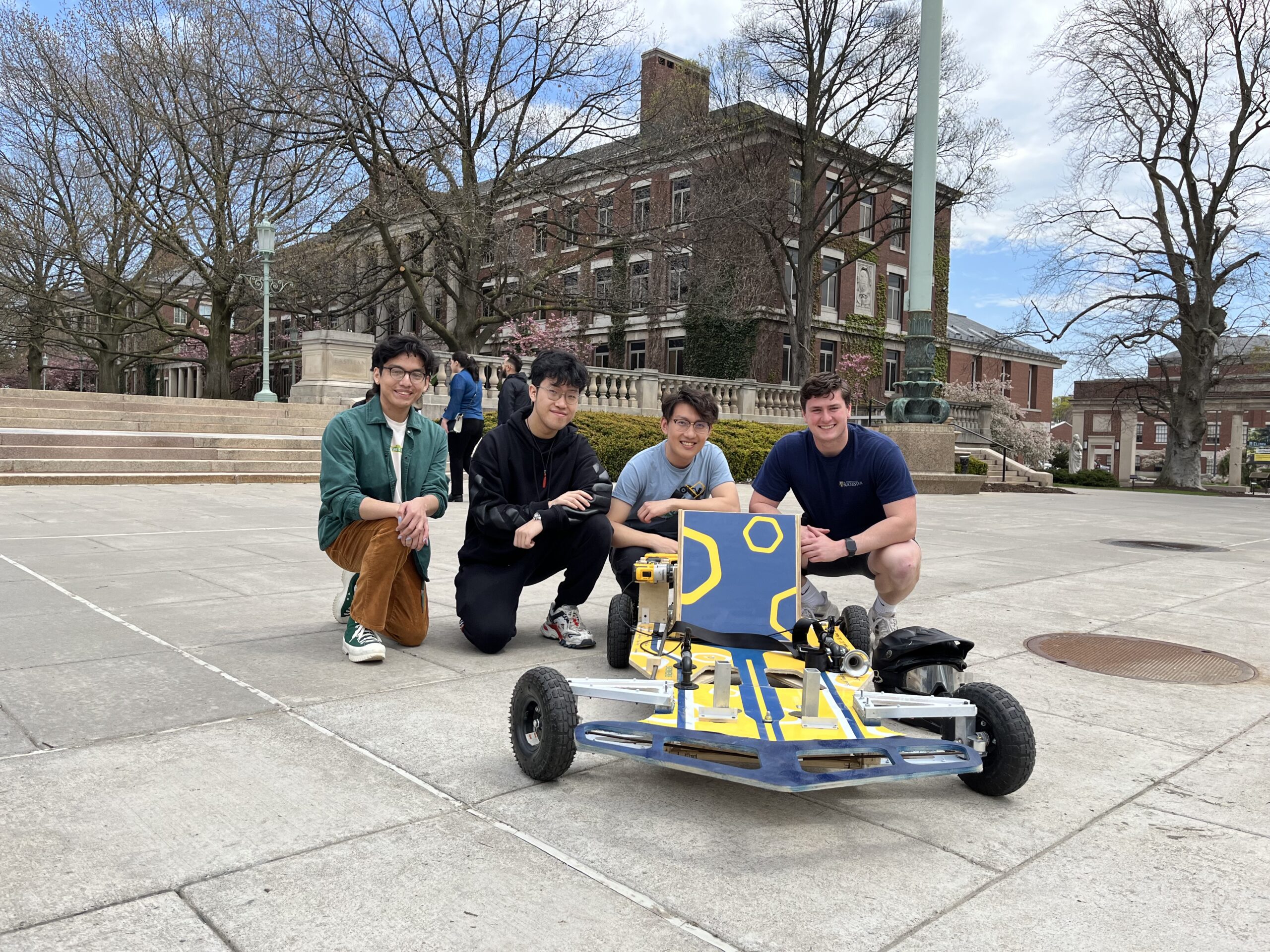
Team Members
- Kevin Contreras
- Nolan Ragland
- Jiatong Sun
- Feiyu Wang
Mentor
Christopher Muir, Chris Pratt, Mike Pomerantz, and Jim Alkins
Project Description
In recent years, there has been a growing trend in alternative and sustainable modes of transportation that are both eco-friendly and cost-effective. Ranging from commercial EVs to green energy public transportation, we see a trend for a more sustainable society with efficient energy consumption. The Drill Powered Cart project aims to explore the feasibility of using standard power drills as the primary propulsion mechanism for small, efficient vehicles to promote sustainable design by repurposing existing tools.
Requirements & Specification
Requirements:
- The vehicle must be steered by feet
- The vehicle must have an in-house designed & manufactured clutch system
- The vehicle’s frame must be plywood and made in-house
- The vehicle must fit any one of the group members
- The vehicle must be powered by a power drill only
- Drill, wheel, and tires must be standardized between both competing teams
- Safety equipment: horn, seatbelt, and guarding
- Race is measured by the distance the carts travel
Specifications:
- The vehicle must complete 1 lap minimum
- Turning radius less than 11 ft
- Maximum brake distance of 15 ft
- Minimum number of 3 wheels
- Maximum speed of 25 mph
- Plywood thickness of 0.5 in
- Weight will be added on to the lighter driver’s car until the driver weight difference is within 5 lbf
- Drivers must switch every 2 laps completed of the race
Concept Design
Frame:
Initial concepts fit the needs of being stiff enough to hold the driver and big enough to fit the other subsystems, while still having a high strength-to-weight ratio to achieve a fast car speed.
Drivetrain:
Different styles of clutch systems & methods include centrifugal, weighted idler pulley, pivoted motor mounting, and axial tension clutching. To deliver the torque a flat belt, v-belt, or roller chain can be used. The concepts that moved forward for our design were the weighted idler pulley and a v-belt.
Steering:
The feet steering mechanism requires a different mounting position than traditional hand steering, hence the design concept started with imitating the normal steering mechanism, converting from rotational to translation motion, but placed close to the driver’s feet.
Analysis & CAE
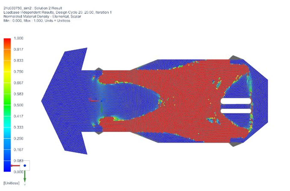
Frame:
To design the frame, NX FEM simulations were used to check the stiffness of the design. Extra frame pieces and beams were added to the design based off these results. A topology optimization simulation was also used to find locations where material could be removed.
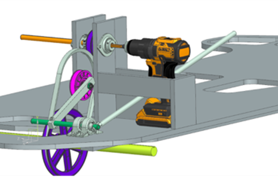
Drivetrain:
Gear ratio, force analysis, and belt sizing calculations were performed using MATLAB to define preliminary material and dimensional constraints. Belt tensioning needed for clutching action was then analyzed through FEA and experimentally refined during manufacturing.
Ergonomics:
The disk braking system was chosen over the regenerative brake and hydraulic brake for greater efficiency and less assembly time. The caliper mount was modeled in CAD to ensure the fitness of the mount to both frame and brake disc. Plywood was cut to match the angle of the mount above the surface and attached to the mount and frame.
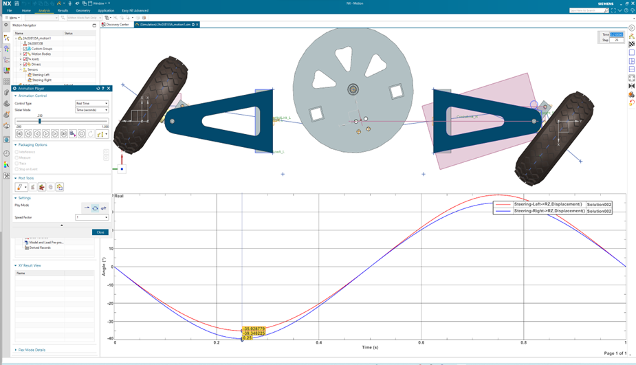
Steering:
Motion analysis and FEM are implemented for steering design. The initial kinematic model is constructed using Siemens NX motion simulation, with point-cloud, allowing for fast results of key steering and dynamic parameters, such as steering angles on both side of the car and turning radius. Load cases inferred from driving speed and weights are further included in NX FEM. Designed parts passed FEA before manufacturing.
Manufacturing
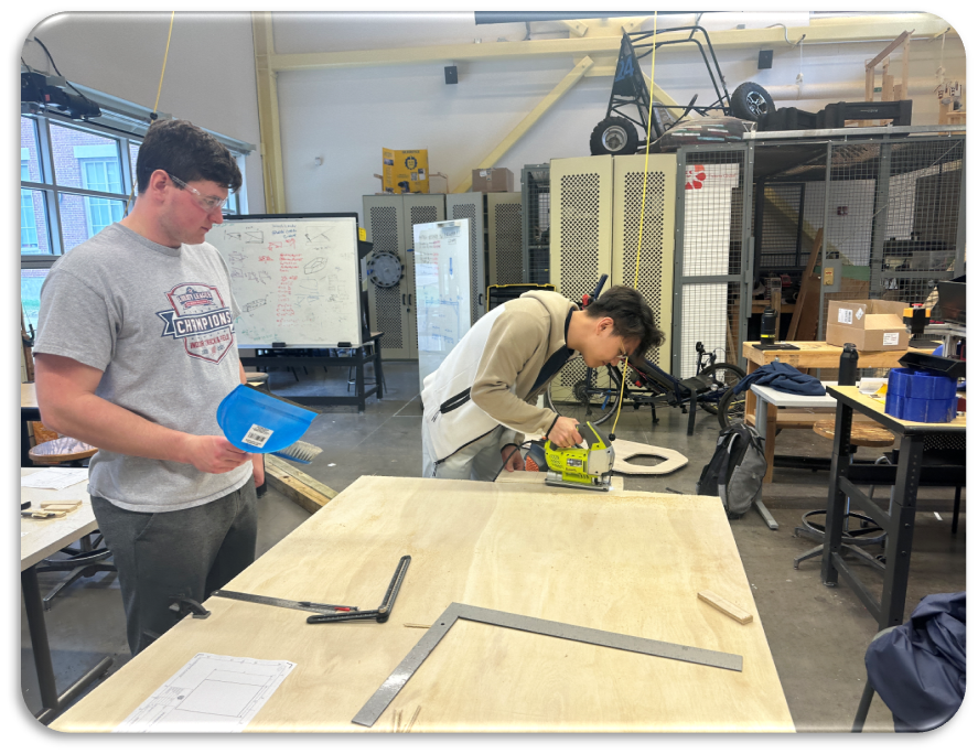
- Wooden parts such as the frame, drivetrain housing, seat, and front chassis arms were cut using the ShopBot, a jigsaw, or the bandsaw.
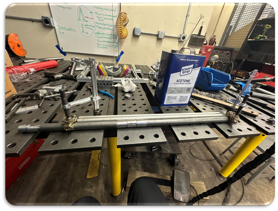
- Aluminum/Steel parts such as steering uprights, keyed-drive shafts, and wheel hubs are machined on traditional milling and lathe machines. Certain parts involved light CNC machining.
- Welding operation has been minimized in the design and is only implemented on the rear driveshaft
Testing & Analysis
Initial Stage:
A stiffness test was conducted on the frame by applying a load to the frame and measuring the displacement.
Secondary Stage:
Partially machined parts including steering uprights, pinion, and frame were test fit and examined before further marching.
Final Stage:
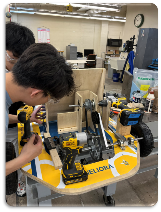
During the final assembly, the drivetrain was tested while stationary and performed as expected. The fully assembled cart completed two laps successfully, though the steering mechanism required tightening. Additional materials were added and more torque to nuts and screws to strengthen the cart.
Each of the requirements and specifications were met and verified through testing. Once the cart was fully assembled, it was seen that the cart was able to drive for the required minimum of laps, maneuvering through turns as required. The cart top speed is below the specified speed limit. The design and assembly follow all requirements and specifications.
Future Works
The next steps for this drill cart would be testing and improving the drivetrain so the drill can operate at high speeds without slipping/stalling and decreasing weight by reconsidering materials and mounting structures.