Team
- Frank Shen
- Ruichen Yang
- Robert Moore
Mentor
Tao Chen (ASML Customer)
Professor Govind Agrawal (Faculty Advisor)
Professor Jaime Cardenas (Advisor)
Vision
The purpose of this project is to create a simulation in MATLAB to model how bending, twisting, and heating a multimode fiber affects the output beam profile and intensity. Understanding how these stresses affect the output of the fiber allows for fine-tuning highly sensitive systems. The simulation will model the output characteristics as light travels through the fiber, giving a rare look at a otherwise inaccessible areas of the fiber.
The deliverable to our customer will be research on the topic on light propagation through fiber and its numerical modeling, the simulation with a user interface, a guide on how to use the simulation, and verification of the simulation.
Background
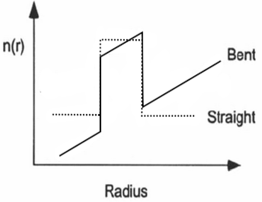
Though the light propagation in optical fibers is assumed to be extremely low loss, many researchers have experimentally demonstrated or simulated that beam profiles in the fiber are sensitive to small changes in the fiber. Therefore, understanding how the geometric distortions and other external perturbations affect the output of a fiber is useful to our customer so that the performance of their highly sensitive system can be improved. Bending, twisting, and external heating are all stresses that create small changes in the refractive index of a fiber, which cause changes in the beam profile and intensity of light propagating through the fiber.
This simulation is particularly useful for highly sensitive systems by predicting how small changes in the fiber geometry affect the output. It also shows a unique view into what is happening to the light as it propagates inside the fiber, which is normally unreachable experimentally.
Method
We used beam propagation method (BPM) to simulate the electric field propagation through the cylindrical waveguide (fiber). The wave equation from Maxwell’s equations to be solved is:
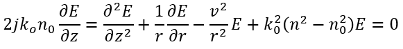
The dimensions in the cylindrical coordinate system can be discretized as r_i=iΔr;z_s=sΔz.
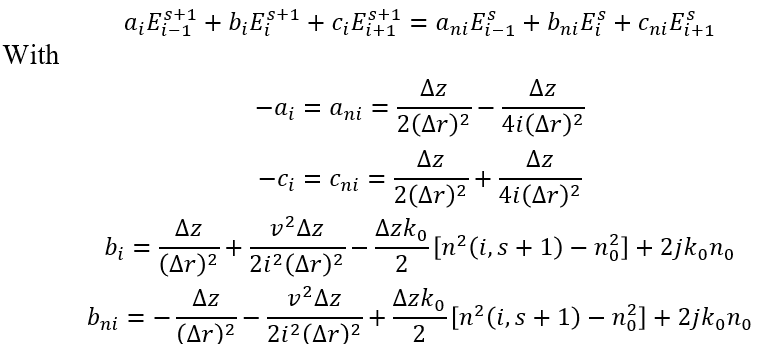
By the Crank-Nicholson scheme, the discretization of the field equations in cylindrical coordinates are in the form of [1]:
Results
Bending:
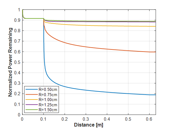
The parameters for this simulation were 0.1 m of straight fiber, 0.5 m of looped fiber of various bending radii, and 0.1 m of straight fiber. The simulation for bending shows that bending the fiber causes an increase in power loss, with smaller bending radii resulting in steeper power drop-offs. We can also see that most of the loss occurs at the beginning of the bending loop.
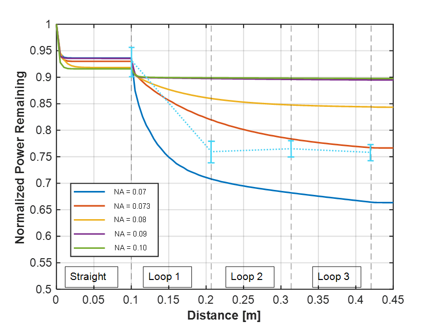
This shows how the fiber numerical aperture, or the difference between the index of the core versus the index of the cladding affect the power loss over multiple loops of the fiber. We can see that the as the index difference decreases, the power loss increases since more light is escaping the core of the fiber.
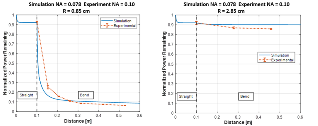
Specific refractive index information is classified by the manufacturer, which makes it difficult to accurately simulate the intensity profile and power. Therefore, we used the experimental data to fit the simulation for one radius (left) and compared the results to the other bending radii (right). As shown in the right figure, the power loss simulation agrees with the experiment.
Twisting:
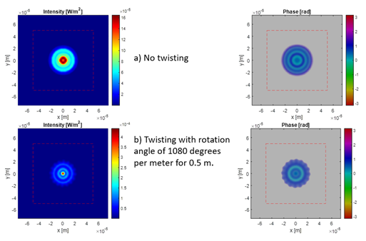
Twisting doesn’t result in much intensity loss, but we do see a change in the beam profile. With extreme twisting, we can see the edges of the beam profile have wavy features.
Thermal:
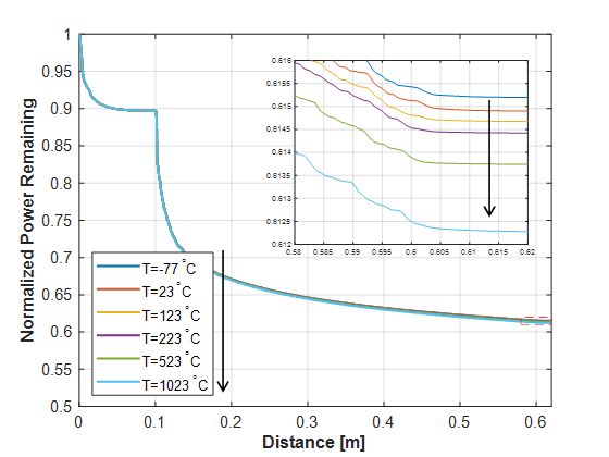
Thermal doesn’t show much difference in the beam profiles, but does show small changes in the output intensity. We can see that as temperature increases, the more power is lost through propagation. The actual loss for temperature ranging from 23°C to 123°C is on the order of 10-4.
Conclusion
The simulation shows that while temperature change and twisting on the fiber do not cause large amounts of change to the output characteristics, the bending radius, index difference between the core and cladding, and core size significantly influence the power loss and near-field output profile. Our simulation program could help our customer to adjust their system to determine the power loss in their fiber system.
Acknowledgements
Thanks to Tao Chen and ASML for all the supports, to Professor Agrawal for technical knowledge, Professor Jaime Cardenas for advice on experiment, and Ed Herger for lab equipment. And thanks to the team who created the open-source MATLAB codes for Douglas-Gunn alternating direction implicit Finite Difference Method.
References
[1] Pollock, Clifford, and Lipson. Integrated Photonics, Springer, 2003.
[2] J. Marcou, Cylindrical 2D Beam Propagation Method for Optical Structures Maintaining a Revolution Symmetry.
[3] Madhu Veettikazhy, “BPM-Matlab: an open-source optical propagation simulation tool in MATLAB,” Opt. Express 29, 11819-11832 (2021).