Team
- Eric Ciocci
- Noah Miller
- Changjie Wu
Mentors
Mark Bocko, Mike Heilemann, Dan Phinney, and Sarah Smith
Design Goals
For the modern guitar player, tone can make or break any performance. Whether playing a live show, recording in a studio, or simply practicing with friends, the amplifier is a key component of music. The gold standard in this area has long been high-end tube amplifiers, providing warm shimmering tone with tons of power. These come with some significant drawbacks however, as many amplifiers are upwards of 60lbs, and can cost more than $1500, far out of the price range of hobby musicians, or those just getting started. Using flat-panel speaker technology, our group seeks to address these problems by designing a low cost and lightweight alternative, that provides the same dynamic tone loved by all, with scalable power to fit all needs.
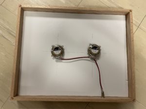
Flat-panel Speakers
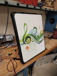
Designed by members of the ECE department, these flat-panel speakers use exciters to vibrate a surface in an extremely specific way, generating very high fidelity sound. Part of the design of the speakers relies on drivers placed in different locations generating different frequency bands, so a crossover is required.
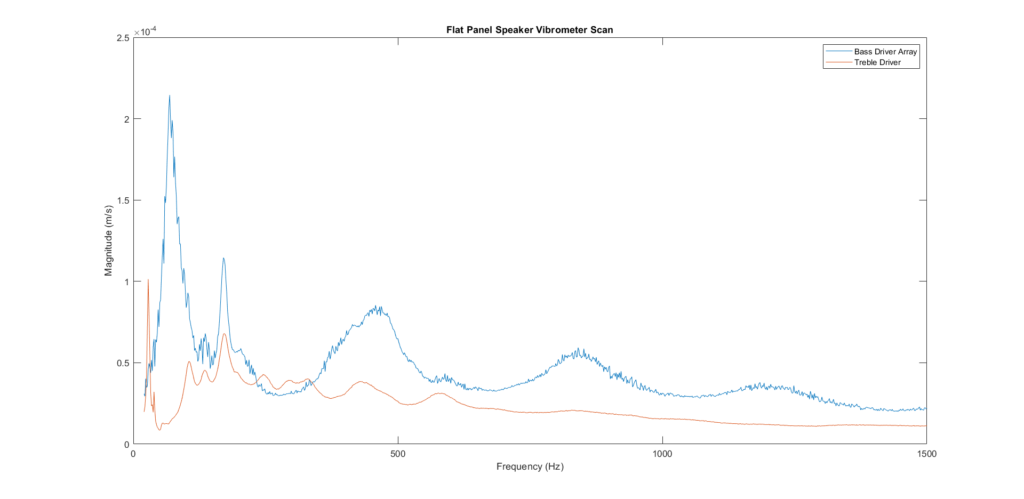
Using a laser vibrometer scan (shown below), the cutoff frequency can be determined for best overall frequency response. We chose 750 Hz for our cutoff, as it presents the most stable response for the treble driver (>750 Hz) and bass driver array (<750 Hz). These speakers are well suited for this project, as they are lightweight, and provide the base for a large amount of power, our specific panel being capable of up to 40W, allowing for scalability in further iterations.
Preamplifier Stage
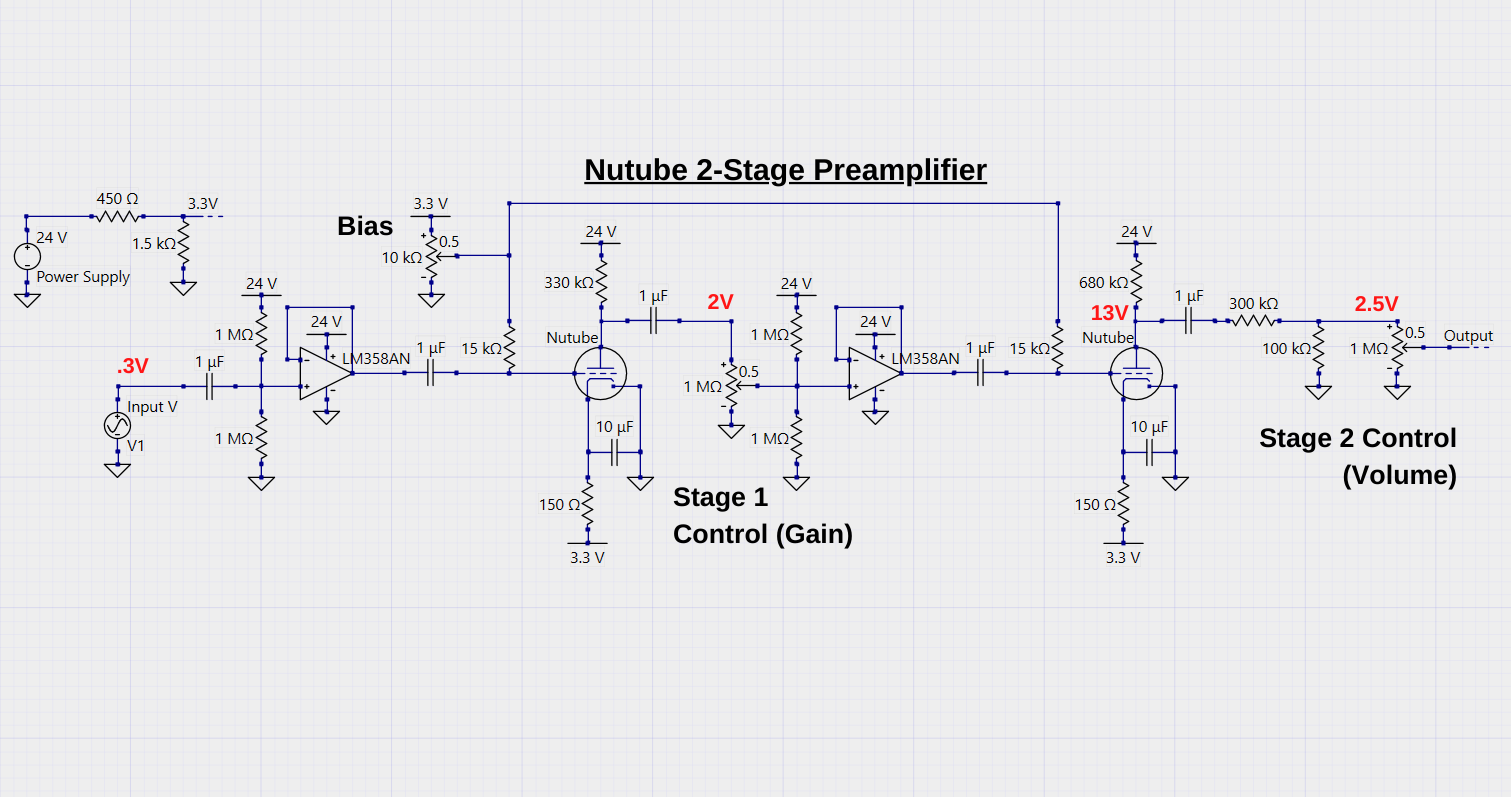
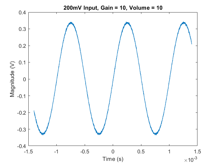
The preamp is the first stage for the input signal of the amplifier. It utilizes two Korg Nutube triodes, which are similar to vacuum tubes – the key component in classic guitar amplifiers. Nutubes offer a unique advantage as they run on much lower voltages than vacuum tubes (often >300V). Here the signal receives amplification and distortion characteristics, essential to the guitar sound. The gain knob controls the output level of the cleaner first stage which drives the more saturated second stage. The volume knob controls the overall preamp output level, which is stepped down at the output. The bias sets the distortion characteristics. The buffers separate each stage as well as the input signal from the amplifier. The values in red above show the signal’s peak-to-peak amplitude across the circuit.
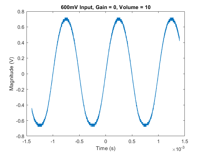
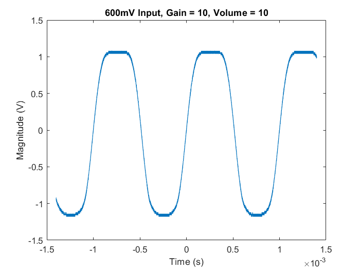
Below, observe the output waveform characteristics at various input voltages and settings. The circuit starts to introduce so-called “overdrive” around an input of 300mV, and by 600mV distortion and clipping are very much present in the output signal.
Tone Control Stage
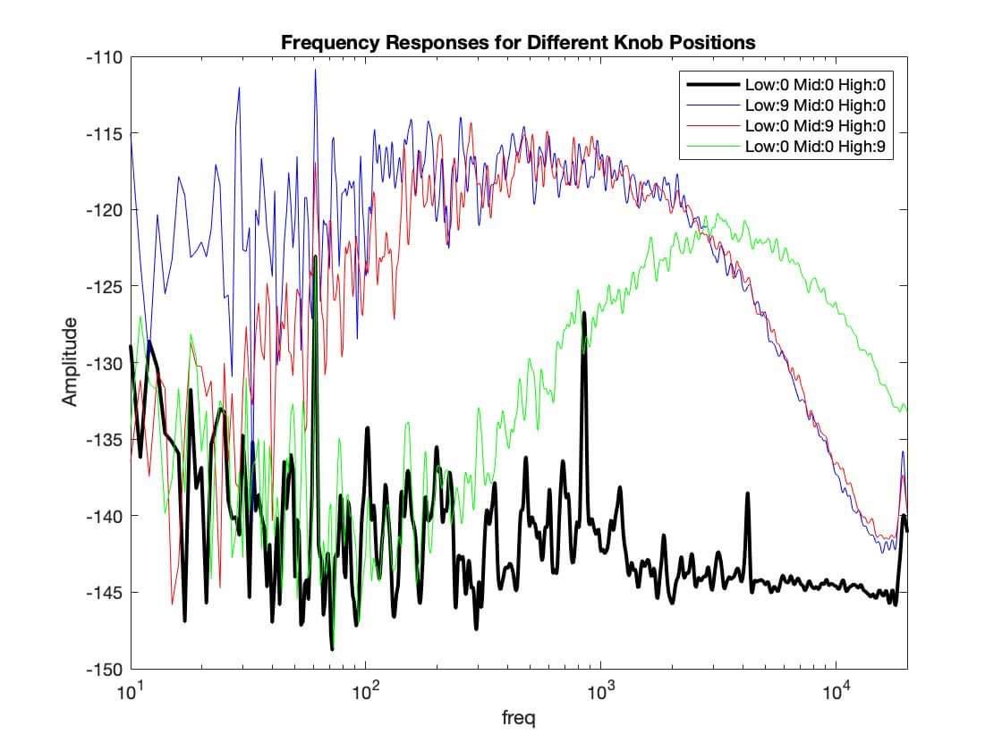
Tone control is one of the essential stage for a typical guitar amplifier, which is usually a two-band/three-band graphic equailizer. In this project, the tone control unit is designed to be a three-band EQ.
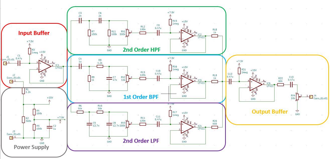
The tone control stage is the second stage with three knobs for bass, mid, treble controls. The output signal from the preamplifier stage goes through an input buffer and splits in three parallel branches.
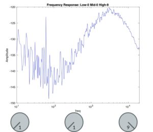
The treble/bass frequency band is then filtered by a 2nd order HPF/LPF to create a sharp drop around the cutoff frequencies; and the mid is filtered by a 1st order BPF.
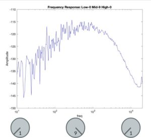
The gain of each frequency band is controlled by three potentiometers. After that, the filtered signals go through three unit gain buffers to prevent interfering with each other and are connected to a common point.
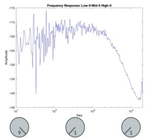
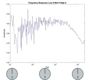
The master volume is controlled by the last potentiometer after the output buffer. This stage is purely subtractive, which means it is attenuating the signal level and could then be amplified by the class-D power amplifier stage.
Power Amplifier Stage
The final stage consists of a Class-D Power Amplifier mixed-signal circuit. A Class-D amplifier operates using an internal oscillator generating a high frequency wave being modulated by the input signal. This signal is then amplified, leaving a large PWM wave which is then filtered using an LC network, leaving an amplified version of the original signal. 
These chips are perfect for our use, as they are capable of a wide range of amplification and power output at a cheap cost, small size, and high efficiency. Texas Instruments manufactures several IC chips that implement these amplifiers, including devices capable of up to 50W of power output. However, due to the ongoing chip shortage, there has been an availability issue with many of these ICs, so tradeoffs had to be made.
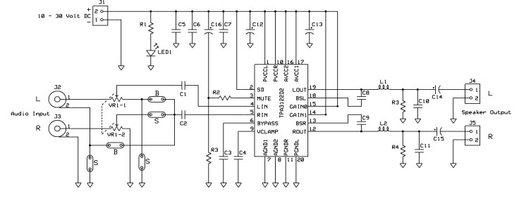
We settled on the TPA3122D2, which would allow us to output 4W through our 4Ω drivers. Although this is a fairly weak output, comparable to smaller practice amplifiers, scaling the output is simple when looking past availability issues.
Discussion
Our final prototype showcases a promising proof of concept. Taken into account the low power output as a result of supply chain issues, the Nutubes provide a warm, dynamic amplification akin to much more expensive amplifiers. With the understanding that further iterations can utilize better ICs to increase output up to 40W, the amplifier achieves our goal of providing a lower cost and lighter alternative for musicians who don’t have the desire or ability to carry around 70lb amplifiers, helping to bring accessible music to all.