Team
- Aayman A Abdellatif
- Samuel B Hauser
- Frederick G Howard
- William T Phillips
Mentors
Professors Jack Mottley and Daniel Phinney
Abstract
The purpose of this project is to design and prototype a semi-autonomous robot that detects a moving target, makes all the necessary calculations, and shoots a small foam ball. This was done by collecting visual target information via an Arduino camera and sending the data as UART commands from a Raspberry Pi 4 to a PIC32MX795F512L. The PIC32 drives DC brushless motors and servos that manipulate mechanisms responsible for yaw/pitch angles, ball feeding, and ball launching. When the right conditions are met and calculations made, the ball is launched at the target.
Construction Design
To achieve the main goal of the project, construction is categorized into three parts – Architectural design, launcher design, and electronics design. Such categorization allows us to focus on each area of the project to ensure the intended operation while also making the testing and debugging process significantly easier/more convenient.
Architecture
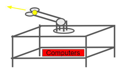
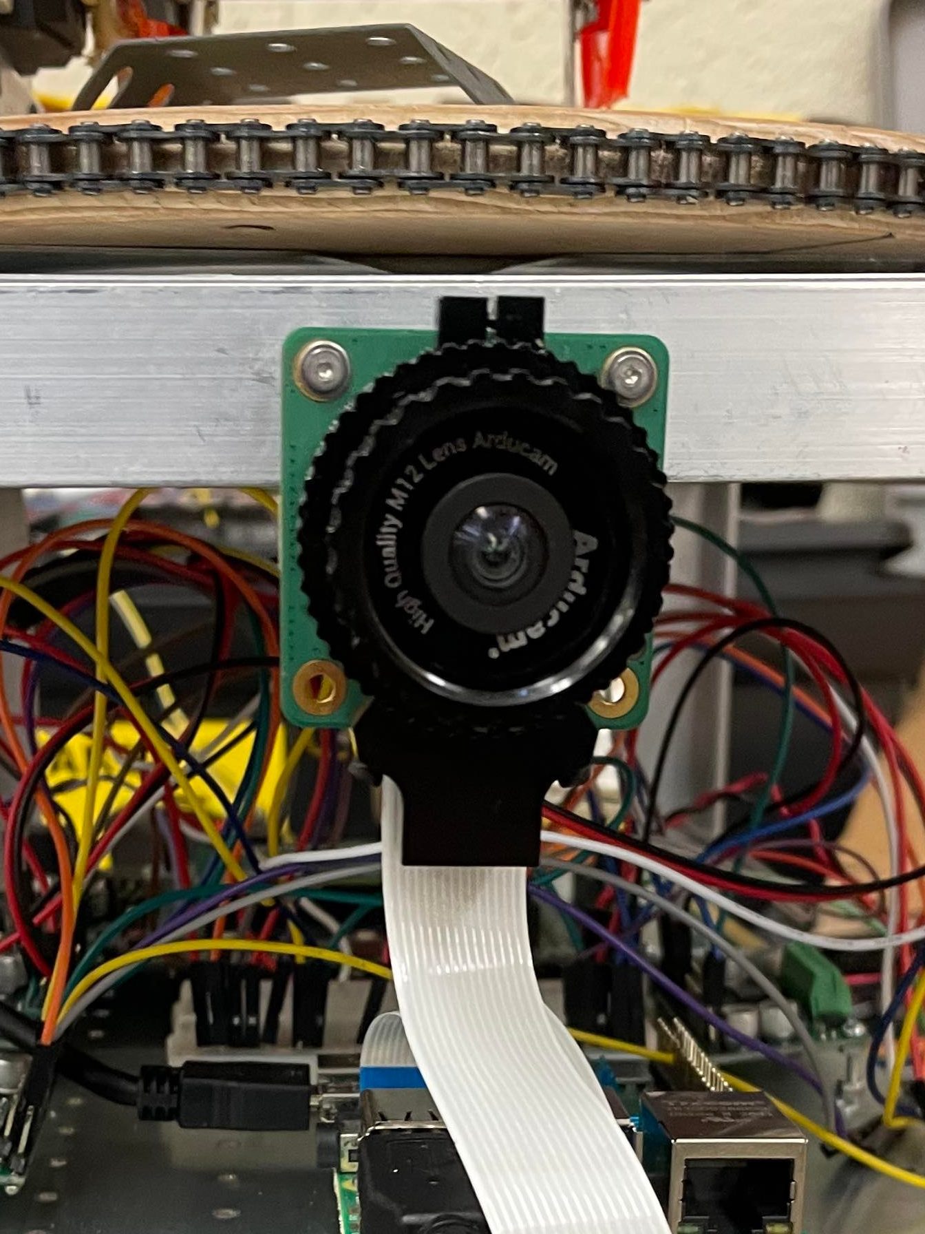
One of the initial concerns when beginning the construction process was how the electrical components would be attached to the physical hardware of the launcher. It was decided that by designating two areas – one for the electrical components and one for the launcher – the electronics would not be compromised by the physical hardware of the launcher while still being close enough to assemble all the necessary wiring. Thus, two platforms – Upper and Lower, each consisting of two steel sheets – are joined together vertically using metal legs. This creates an interior area in between the two platforms where all electrical components – the PIC32 board, Raspberry Pi, and H-bridges – are bolted onto the lower platform with the camera attached to the side of the upper platform.
The upper platform serves as the foundation of the launcher. All components and attachments regarding launcher design are bolted onto the lazy Suzan that sits on this platform.
Launcher
There are two main constraints in the design of the launcher: how to manipulate pivoting/swiveling motion and how to feed in the small foam balls. Due to functional restraints with the ordered camera lens, the Arduino camera is limited to a 90° field of view (45° on either side of each axis). As such, it was not necessary to design a swivel that rotates the entire launcher a full 360°, as it exceeds the working FOV. This allowed for a lot of leniencies when applying the concept of a bike chain pulley as our swivel operation. Using basic nails, a chain is attached to the circumference of a wooden disc of 22 cm diameter and 2 cm thickness. The nails are strategically placed so that when the chain is driven by a motor, there is no interference in the first 90° range motion. This contraption is bolted down onto a lazy Suzan and sits on the top platform.
Regarding the angle pivoting, the initial goal was to align the capabilities of the launcher to that of the Arduino camera’s 45° vertical FOV (+y-axis). However, initial testing revealed that the physical size of the construction materials and device interfered with its launching operation. Even after altering the physical size of the materials, the imposition of a pivot of 20° up and down was adopted into the design. This motion is driven by a low-power servo attached to the base of the launcher.

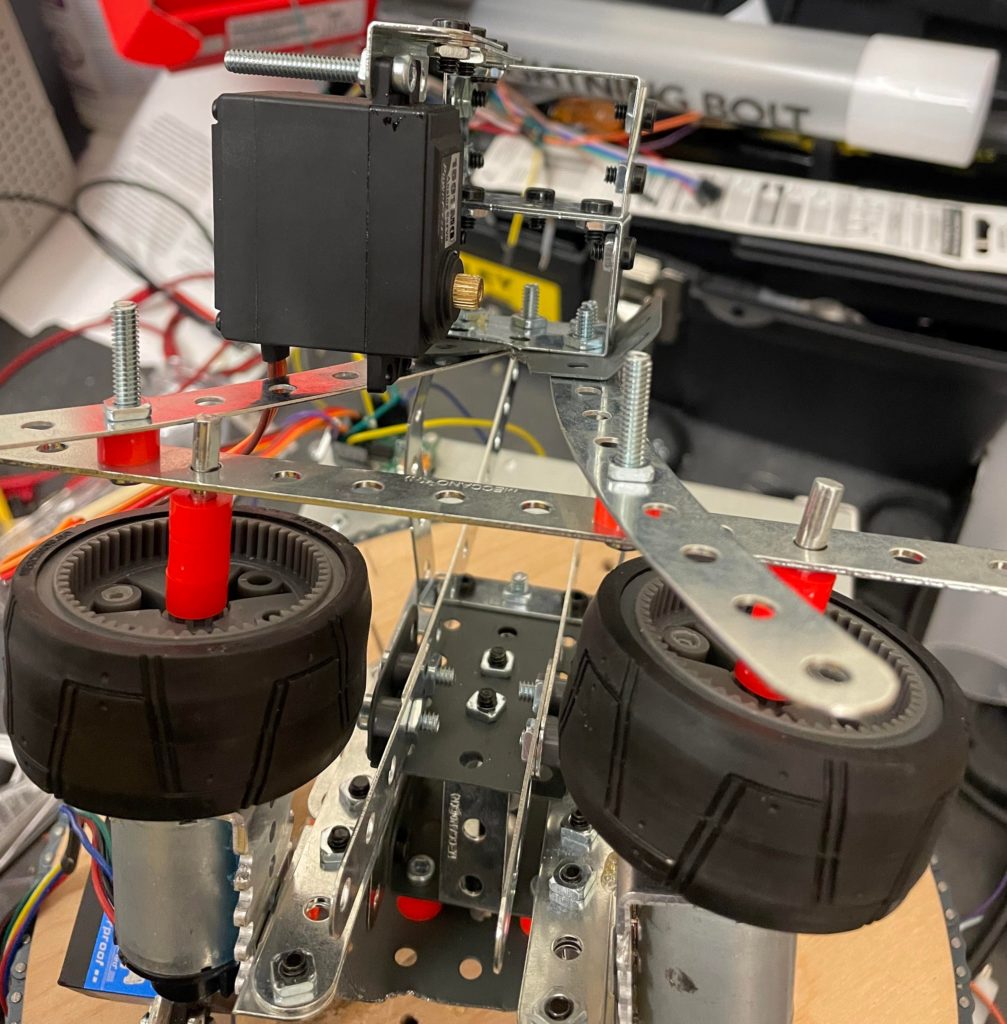
The second constraint revolves around how to feed the balls into the launcher. Ideally, the ball would be fed automatically through a geared feeder, similar to that of our reverse-engineered commercial launcher. However, this concept was scrapped in the interim as there were too many limitations with the physical materials when it came to device testing. As a result, we experimented with the concept of a scissor lift, where the two spinning motors close in on a ball at rest. Discussions with the Professors, however, resulted in the conclusion that it was best to have the motors be stiffly attached to the launcher. As a result, we settled on the idea of manually feeding the ball into the gap between the two motors, using gravity as an external force to drive momentum. As such, we attached two long, curved metal bars to guide the ball from the top of the launcher down into the spinning motors.
However, as the design process came to a close, and testing concluded, we decided to revert to our original design of automatically feeding the ball into the launcher using a low-power servo motor at the top of the exoskeleton. Using two axles, the servo spins with enough force to propel the ball – resting on the curved bars – into the gap between the two wheels. Testing proved this to be sufficient.
Troubleshooting:
Overall launcher design was constantly tweaked as more and more complications arose throughout its construction. One such complication was the lack of stiffness in the motors. Initially, each of the two motors that drive the wheels has a gearbox. However, to consistently drive the motors at maximum speeds, the gearboxes were removed, resulting in an unforeseen consequence where the motors, and the wheels being spun, violently vibrate and detach from the launching platform. Furthermore, without a gearbox, the motors lack torque, making it very easy for other forces, such as gravity, to act upon the system, drastically reducing spin-speed when the pivot is at its maximum inversion. For the first complication, we were left with two choices – either reattached the gearboxes, reducing overall speed, and thus, distance, or make the system stiffer to discourage detachment. We opted for the latter by adding brackets to the exoskeleton as well as plastic separators and a series of metal bars, serving to add weight to the system. For the second complication, repositioning the motors to be bolted down from the bottom rather than the top as well ramping the pivot (using delays) instead of having it switch to angles aggressively proved to be sufficient in reducing the impacts of external forces on the system.
Software Design
Localization & Targeting
When discussing project design, the team decided that it would be best to have certain parameters pre-defined/constant – Focal Length and target size. Using these parameters, we can deduce depth using similar triangles and ray optics by employing the OpenCV library
AruCo Board
Employing the use of an AruCo board as our “target” allows us to easily localize a target in a fixed frame from real-time visual data. Since the size of the board is constant (pre-defined), we can estimate the pose of the camera with respect to the four corners of the board, thus tracking the overall position of the target regardless of motion. Thus, by using built-in methods of the OpenCV library to calculate the four corners, we can continuously target and track the center of the AruCo board relative to its size.

Below is an example of the code, written in Python, using the focal length of a MacBook Pro camera:
#!/usr/bin/env python
# coding: utf-8


import numpy as np
import cv2
import cv2.aruco as aruco
import math
#side of square is currently 8.25 inches or 20.955 cm
f = 5 #focal length of mac = 5 cm
D = 20.955


def lengthCalc(lengthOfSide, topLeftCorner, topRightCorner, bottomLeftCorner, bottomRightCorner):
    lengthTop = ((topRightCorner[0]-topLeftCorner[0])**2+(topRightCorner[1]-topLeftCorner[1])**2)**.5
    lengthBottom = ((bottomRightCorner[0]-bottomLeftCorner[0])**2+(bottomRightCorner[1]-bottomLeftCorner[1])**2)**.5
    conversionFactorTop = lengthTop / lengthOfSide
    conversionFactorBottom = lengthBottom / lengthOfSide
    print("Top length: " + str(lengthTop))
    print("Bottom length: " + str(lengthBottom))
    print("top = " + str(conversionFactorTop) + "pixel/cm")
    print("bottom = " + str(conversionFactorBottom) + "pixel/cm")
    return (lengthTop ,conversionFactorBottom)


def depthCalc(f, d, D):
    Z = 2*D*(f/d)
    ##print("Depth: " + str(Z*3.28) + "ft")
    return Z


def centerBox(topLeft, topRight, bottomLeft, bottomRight):
    y=(max(topLeft[0],topRight[0],bottomLeft[0],bottomRight[0])+min(topLeft[0],topRight[0],bottomLeft[0],bottomRight[0]))//2
    x=(max(topLeft[1],topRight[1],bottomLeft[1],bottomRight[1])+min(topLeft[1],topRight[1],bottomLeft[1],bottomRight[1]))//2
    return (int(y),int(x))

def calculatePitch(distance,height,velocity):
    g=9.8
    valueUnderSqrt=-(distance**2)*((g**2)*(distance**2)+(2*g*velocity**2*height)-(velocity**4))
    numerator = velocity**2*distance-math.sqrt(varrible)
    argument=varrible2/(g*distance**2)
    return math.atan(argument)

dictTag = cv2.aruco.DICT_ARUCO_ORIGINAL

tag = np.zeros((300, 300, 1), dtype="uint8")
ID = 24

arucoDict = cv2.aruco.Dictionary_get(cv2.aruco.DICT_ARUCO_ORIGINAL)
cv2.aruco.drawMarker(arucoDict, ID, 300, tag, 1)

cv2.imwrite('TagTest.png',tag) #creates tag, stores in tagtest
cap = cv2.VideoCapture(0)  # Get the camera source


while True:
    ret, frame = cap.read()
    if not ret:
        print("failed to grab frame")
        break
    gray = cv2.cvtColor(frame, cv2.COLOR_BGR2GRAY)  # Change grayscale
    aruco_dict = aruco.Dictionary_get(cv2.aruco.DICT_ARUCO_ORIGINAL)  # Use 5x5 dictionary to find markers
    parameters = aruco.DetectorParameters_create()  # Marker detection parameters
    corners, ids, rejected_img_points = aruco.detectMarkers(gray, aruco_dict,parameters=parameters)
    centerX, centerY, other = frame.shape
    size = 1
    center = (centerY//2, centerX//2)
    if type(ids) != type(None) and len(ids) <= 1:
#         print(corners)
#         print()
#         print(corners[0][0][0]) #top left corner
        d = lengthCalc(D, corners[0][0][0], corners[0][0][1], corners[0][0][2], corners[0][0][3])
        distance=depthCalc(f, d[0], D)
        aruco.drawDetectedMarkers(frame, corners)  # Draw A square around the markers
        point = centerBox(corners[0][0][0], corners[0][0][1], corners[0][0][2], corners[0][0][3])
        print("Y,X: " + str(point))
        cv2.circle(frame,point, size, (0,0,255), 5) #center of box
        offsetFromCenter = (point[0] - center[0], point[1] - center[1]) #how far away
        #print(offsetFromCenter)
        #velocity=10
        #theta=calculatePitch(distance,centerY/d[1],velocity)
        pitch =(point[1] - center[1])/center[1] * 45
        yaw =(point[0] - center[0])/center[0] * 45
        print(str(yaw)+","+str(pitch)+",0*")
        #print(offsetFromCenter)
    centerX, centerY, other = frame.shape
    size = 1
#     cv2.circle(frame,(centerY//2,centerX//2), size, (0,0,255), 5) #center of frame


    cv2.imshow("test", frame)
    cv2.waitKey(1)

cap.release()
cv2.destroyAllWindows()
Pivot (Pitch) & Swivel (Yaw)
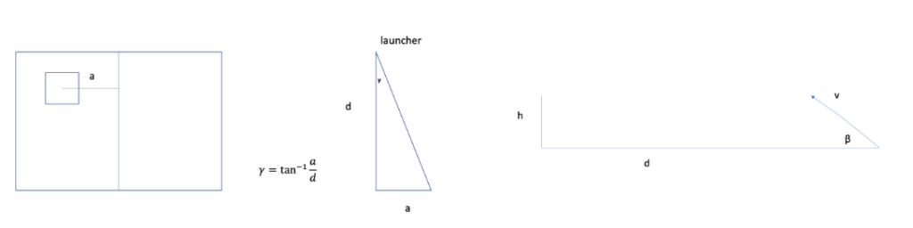
Using the default limits of the Arduino camera (45° in either direction), the maximum pitch angle (β) is calculated using trigonometric ratios with the distance to the target (d) and height of the target off the ground (h). For yaw, angle (γ) is calculated by tracking the total range of width motion (a) with distance (d) using similar triangles.
From these calculations, data packets are sent using three parameters as strings:
(“X”, “Y”, “Z”)
Where X and Y are the angles of Yaw & Pitch, respectively, calculated from target localization, and Z is a binary that commands the launcher (0 for Standby; 1 for Shoot).
Data packets with pitch and yaw commands are generated by the Raspberry Pi and sent to the PIC32 board via the UART communication protocol. To compensate for the occasional issue of missed packets, identical packets are continuously sent.
Driving Motors & Servos
The project consists of two types of motors – three DC Brushless motors and two servos. The servos are employed in the pitch and ball feeding mechanisms while the DC motors drive the swivel and actual ball launching mechanisms.
Servos are connected through a special servo board that generates PWM signals based on UART commands from the Raspberry Pi to the PIC32 board.
The DC motors are connected to the PIC32 through an H-Bridge and are always driven at maximum speed. However, the DC motor responsible for the yaw motion operates with a ± 2° bit-band. This, along with the use of a quadrature encoder keeps track of the state/position of the motor as it rotates the entire launcher back and forth. The two other DC motors are responsible for ball launching and are “bang-bang” controlled, meaning they are driven at maximum speed until the supplied power is cut or are manually stopped via commands.
Launcher Demonstration
Conclusions
This project allowed us to holistically combine several experiences across four years of the electrical & computer engineering major to create a semi-autonomous robot that tracks a target, makes all the proper calculations, and aims/shoots a ball. From image processing in ECE 247 to microcontroller communication in ECE 216, we were able to combine so much knowledge in a year to create something that not only meets expectations but allowed us the opportunity to refresh on certain material and become more well-rounded engineers.