Team – William Bellows, Joe Bumpus, Alex Mancuso, Nicholas Muscarella
Mentors – Mike Heilemann, Sarah Smith, and Dan Phinney
Abstract
The Gavett Hall Recording Studio is well known amongst AME students for its beautiful design, incredible resources, and signature reverb. Although this reverb is loved and embraced by many, some students wish for the ability to limit this sound for more control in post production. The aim of this project was to create a modular solution for this issue, capable of treating the sound with the option of leaving it intact. The studio’s current acoustic properties—impulse and frequency magnitude responses, respectively—were first measured to identify the current acoustic profile of the room. With these results in mind, the final design is a mobile acoustic panel tailored towards minimizing reflections from the ceiling and walls, absorbing the most reverberant frequencies shown in our data. Simulated results of multiple acoustic panels in the studio show a promising decrease in reverberation time, and make a strong case for further investment from the AME/ECE Department.
Pre-Planning and Control Measurements
To ensure measurements were not impacted by equipment bias, the system was first measured in the CSB Whisper Room (semi-anechoic chamber). The measurement equipment system included:
● MATLAB impulseResponseMeasurer
● Universal Audio Apollo Solo (interface)
● Behringer ECM8000 microphone
● JBL 308P MkII & LSR310S monitor/subwoofer
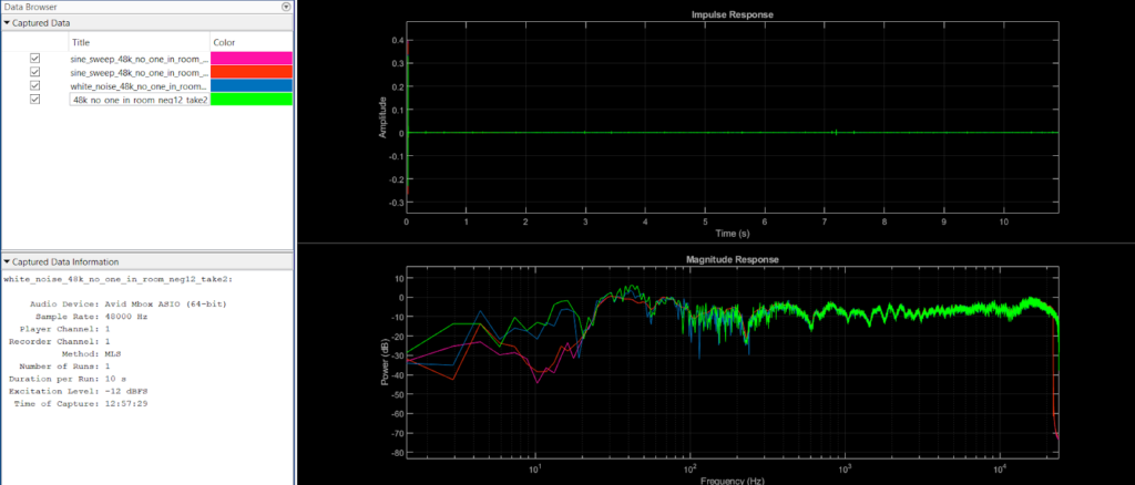
Four measurements—two exponential sine sweeps and two white noise—showed a similar flat response, almost identical from 300Hz-20kHz (important as suspected reverb issue lies in high mid frequencies). These measurements are as seen below:
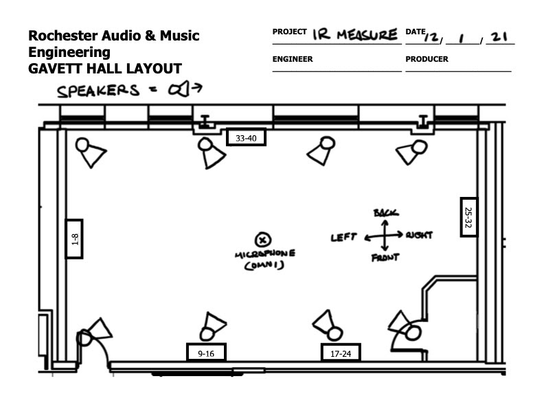
Gavett Studio live room was then measured from 10-22kHz using s exponential sine sweeps with 5s silence between runs for maximum frequency resolution. Measurements were taken in eight locations around the studio (shown below, with front right middle microphone/speaker placement as an example) in order to identify differing acoustic properties associated with architectural design.
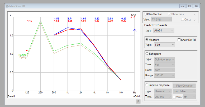
Control Measurement Results
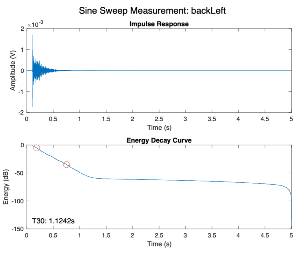
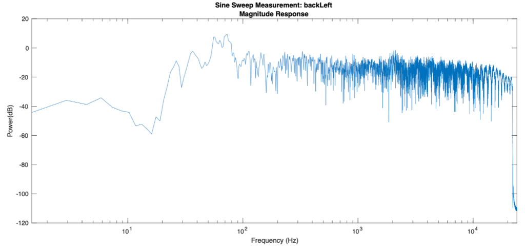
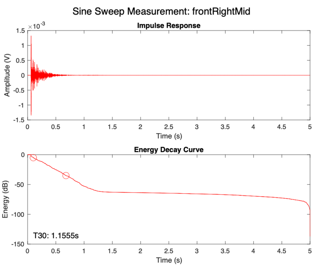
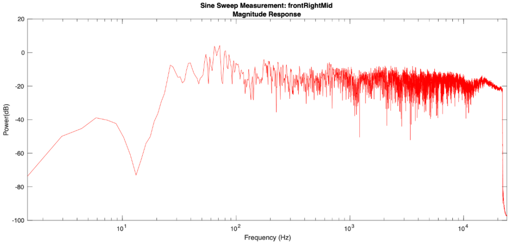
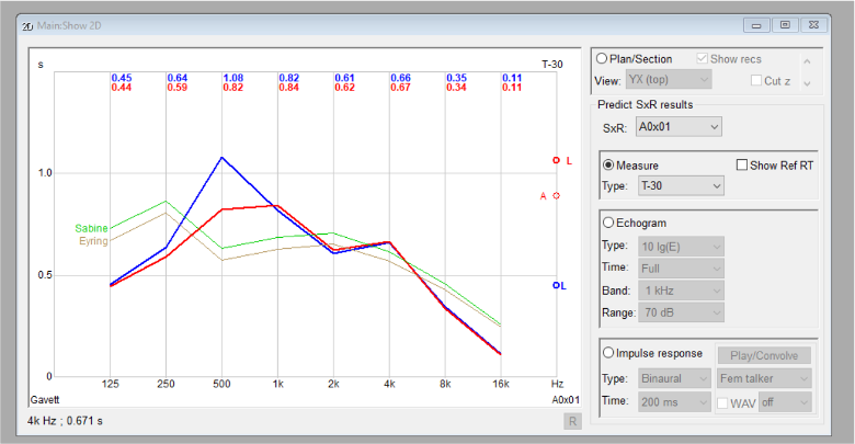
The measured data was processed to determine the room frequency magnitude response and the energy decay curve, allowing for the calculation of RT60 (the time after a sound source ceases that it takes for the sound pressure level (SPL) to reduce by 60dB). The impulse response was processed with a ⅓ octave band filter applied at American National Standards Institute defined center frequencies. For the purpose of this data, RT30 (two times the time for SPL to decrease by 30dB) was used as an estimate to avoid hitting the noise floor. Results showed ordinary reverberation time. There is an expected dense reverb around 1kHz, tapering off drastically at lower frequencies but staying mostly equal or slowly decreasing as frequencies get higher. There is no distinct difference between locations, as can be seen from the two sets of plots below, one from the back left of the room and one from the front right middle, as examples. This consistency suggests reflections from the floor and ceiling. The impulse response from each of these two measurements can be heard below.
Mobile Acoustic Shield Design
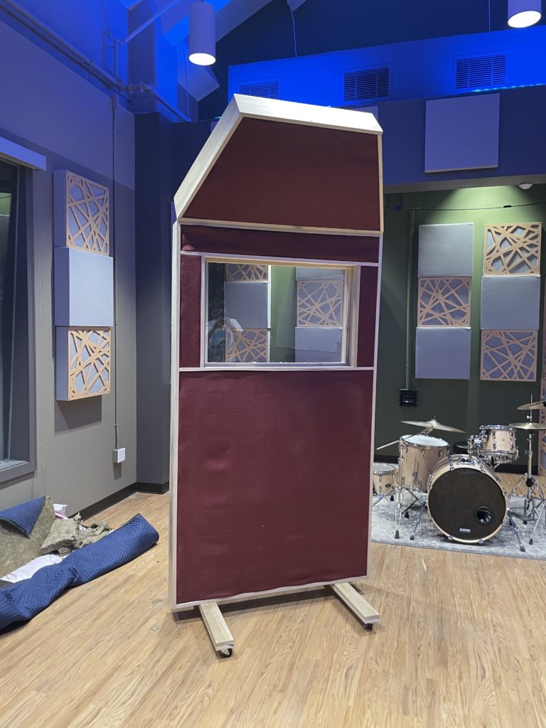
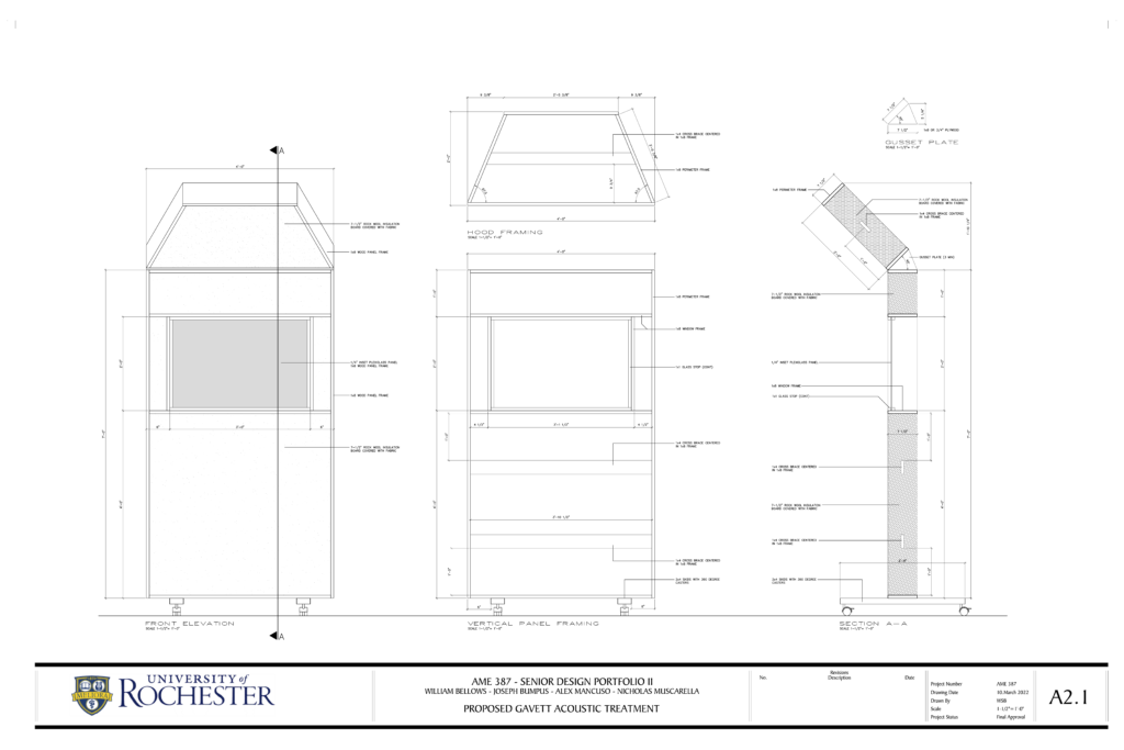
The final design is a mobile acoustic shield featuring an angled hood to limit reflections to and from the ceiling. The sides of the hood are angled inward to allow for six shields to form a mobile hexagonal isolation booth, or any combination of 2-6 panels to angle off instruments while recording. The frame contains multiple cross braces for structural support but leaves space for 6” of ROCKWOOL Safe’n’Sound sound absorbing insulation, chosen for its high noise reduction coefficient and low cost. The exterior is lined with ATS sound absorbing burlap fabric. The shield features a plexiglass window to allow for visual communication while recording.
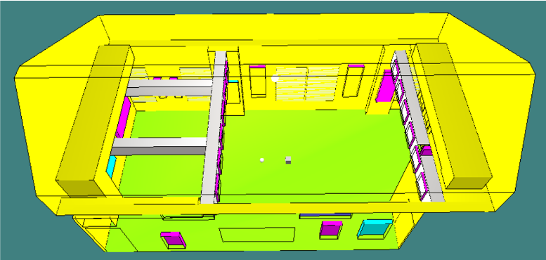
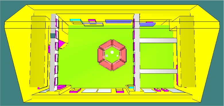
Simulated Full Design
CATT-Acoustic—a software for room acoustics prediction and auralization—was used to simulate the effects of the full design as time and budget allowed for building only one. To compare with our control measurements, the studio’s T30 was first simulated without the acoustic shields in place. The sound source and receiver were placed in the center of the room. This current studio layout simulation shows a comparable T30 to the measured data, only slightly higher. Some approximations (including leaving out the piano, drumkit, and ceiling ridges) were made, likely accounting for this difference. The figures below show both this simulation and the simulation including the hexagonal room design.
For each simulation, the room impulse response was convolved with a simple guitar track, as can be heard below. The treated room guitar signal is immediately noticeably clearer with greatly reduced reverb.
Discussion
In our simulations, the hexagonally arranged shields reduced the T30 by over 50% from 1k-16kHz, extremely significant as our identified problematic region was above 1kHz. While not completely deadening the sound projected from a loud source in the studio, the acoustic shields are effective in reducing the amount of sound reflected from the ceiling, walls, etc. The shields would be extremely effective in recording several instruments/sources at the same time while minimizing bleed (the spill of sound from a source into the close-mics of another instrument). They would serve as a highly versatile recording tool, allowing the user to shape the room however they want for any session. With simple modifications (such as having varying degrees of width between the base skids), multiple panels would easily store flat against one another to ensure the current acoustic properties of the room remain intact.
We currently have one acoustic panel built as a prototype which we will use to pitch our design to the AME/ECE Department. We hope to receive support from the department so that we can craft more panels and implement our full shell-like design in the Gavett Studio.