Table of Contents
- Problem Statement
- Team Members
- Background Information
- Project Phase Breakdown
- Design Overview and Prototyping
- Testing Methods and Results
- Next Steps
- Acknowledgements
Problem Statement
To design and develop a “smart” broaching system that is capable of collecting data and providing live feedback to an orthopedic surgeon to guide them throughout the broaching process of a THA to ensure optimal placement of a hip replacement stem in the patient’s femur.
Team Members

Supervisor
Dr. Whasil Lee, Ph.D., Department of Biomedical Engineering, University of Rochester
Stephen Wells, CMTI Student, University of Rochester
Customer
Dr. John G. Ginnetti, MD,
Division Chief Adult Reconstruction,
Department of Orthopaedics and Physical Performance
Background Information
Nearly half a million people get a total hip replacement in the US every year, with an early revision rate of 3.1% due to stem dislocation. In total hip arthroplasty (THA) a broach is used to create a channel in the thigh bone (femur) for insertion of the femoral implant. Problems arise when the channel created does not perfectly match the implant that needs to be inserted, thus leading to off-axis insertion, bone fractures, and aseptic loosening. For these reasons, our project aims to make improvements to the current broaching process, in order to reduce surgeon-related factors that lead to early revision surgery.
The target customer for the Smart Hip Broaching System is an orthopedic surgeon who performs total hip arthroplasty surgeries. There are 5 different surgical approaches to the hip while performing a THA, the most common being the posterior approach and the anterior approach. There are additionally the medial, direct lateral, and anterolateral approaches. This broaching system is designed to assist the surgeon by providing guidance during the broaching process of any of the five approaches to THA surgery.
The Smart Hip Broaching System consists of an orthopedic mallet and THA broach handle with a sensor system to provide live feedback throughout the broaching process on the amount of force being exerted by the mallet, as well as the longitudinal and rotational movements of the broach as it enters the medullary canal. This data assists orthopedic surgeons in ensuring optimal placement of the femoral stem implant in the patient’s proximal femur and additionally can be used as a preliminary analysis of the patient’s bone quality.
Project Phase Breakdown
Phase 1
Phase 1 is a research motivated phase that will be focused on collecting and analyzing data to develop force thresholds and develop a qualitative system for characterizing different bone types. In this phase, our sensor system is attached onto the reusable broach and mallet currently used in THA, and these sensors will collect the necessary force and angular measurements in clinical trials. Patients will be enrolled in the clinical trial, and the surgeon will perform THA as normal with our sensor system attached to the broach handle and mallet. Data will not be displayed to the surgeon, and instead used post-operation to determine the correct thresholds for different bone types.
Phase 2
Phase 2 involves manufacturing the entire smart broaching equipment, consisting of a Smart Broach Handle and Smart Ortho Mallet, with an internal sensor system in the broach shaft and the mallet head. During Phase 2, the established thresholds of the analyzed data from the clinical trials will be implemented and used to alert the surgeon when the threshold is met, aiding them in optimally placing the prosthetic stem in the medullary canal.
Design Overview and Prototyping
The initial prototype created was going to use arrays of force sensitive resistors (FSRs) on the broach handle to measure the rotational torques placed on the broach handle. The prototype began with a single FSR hooked directly into an Arduino Uno, and controlled by the Arduino IDE. A second FSR was added soon after on the opposite side of the handle to measure the torques in both directions or rotation. Lastly, a buffer amplifier and low-pass filter was added to each FSR circuit to reduce the amount of noise in the outputs. This FSR approach was eventually abandoned due to the relative inaccuracy of the FSRs and somewhat complicated circuitry needed.
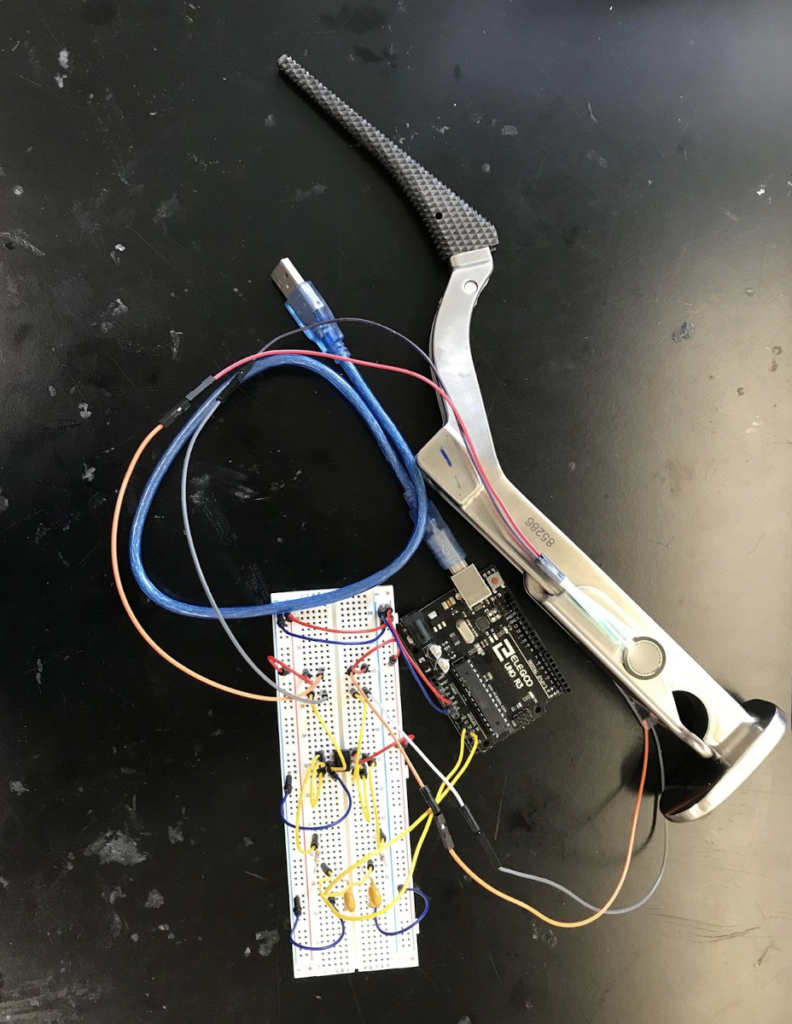

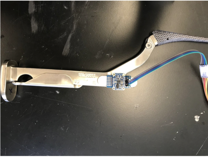
The second prototype was initially going to incorporate one Adafruit BNO055 Absolute Orientation breakout board on the broach handle, which would contain a gyroscope, accelerometer, and magnetometer, to give us a significant amount of data about the movement and orientation of the broach handle. This BNO055 board would be used in conjunction with the FSRs, however we realized rather than measuring the torques placed on the broach handle, we could instead measure the degree of rotation of the broach handle about the long axis of the femur, and gather data with the same relevancy. This allowed us to remove the FSR portion of the prototype and use only the BNO055 breakout board. The breakout board was mounted to the hip broach handle, connected to an Arduino Uno by a roughly made cable, and then the Arduino Uno was connected to a host computer to power the system and collect data.
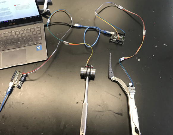
For the third key prototype, which we are still using for our main data collection, we added a second BNO055 breakout board to the head of a surgical mallet in addition to the one on the broach handle. This allowed us to measure both the impact force of the mallet onto the broach handle, as well as the force imparted onto the patient’s femur by the broach handle. For this prototype each BNO055 board was hooked into an Arduino Uno by a more established, but still makeshift cable, and the Arduino Uno was then connected by cable to a host computer. They were both controlled by MATLAB and operated in “AMG” mode, which integrates the sensor readings to output the acceleration and angular velocity of each BNO055 in 3 dimensions.
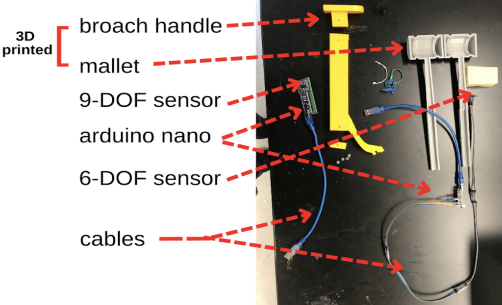
Our final prototype utilizes 3D printed models of both the mallet and broach handle as well as smaller Arduino Nano microcontrollers. Within the mallet model, the head and handle are hollow which would allow us to place an MPU6050 6-DOF breakout board within the mallet head, and run the wiring down the handle, and connect it to an Arduino Nano outside of the mallet, and then connect the arduino to the host computer. Similarly the main shaft of the broach handle 3D model is hollow allowing us to place a BNO055 9-DOF breakout board inside the broach, and run the wiring to another Arduino Nano, and then to the host computer. This prototype solves some of the sterilizability concerns, since the sensor breakout boards would no longer come into contact with biological material, and would not have to be sterilized, they would simply have to be taken out of the instruments before the instruments were sterilized as normal. Additionally, this prototype is an improvement regarding wire management since the wires protruded directly from the end of the mallet handle, and from the bottom of the broach handle, so they would not be impeding the surgeon as much during a procedure.
Testing Methods and Results
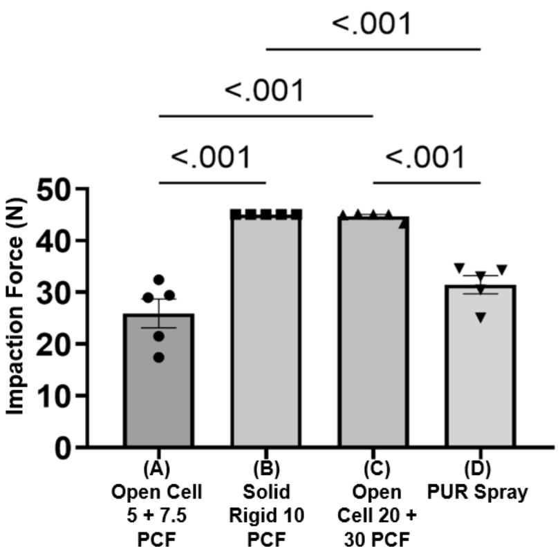
We conducted mechanical testing of our system on four different bone-like materials to ensure the force measuring component of the mallet could differentiate between different bone-like materials while the broach is being impacted into bone.
In order to determine whether the materials could be detected, the broach was malleted into four different materials, listed below:
Material A
Open Cell Rigid Foam Block (5 PCF) stacked on an Open Cell Rigid Foam Block (7.5 PCF)
Material B
Solid Rigid Polyurethane Foam Block (10 PCF)
Material C
Open Cell Rigid Foam Block (20 PCF) stacked on an Open Cell Rigid Foam Block (30 PCF)
Material D
Polyurethane Spray Foam Block
To conduct the test, the mallet (with an accelerometer attached) and broach handle were set up and connected to MATLAB to record the live acceleration data. Each of the materials listed above were clamped into a vice clamp and malleted into 5 times. The peak acceleration of the mallet was recorded from the graphs generated on MATLAB and converted to impaction force using Newton’s second law (F=ma).
Next Steps
While developing our prototype, our team considered factors that may limit us from further development and steps we need to take to mitigate those constraints.
Regulations
The regulatory process of the smart hip broaching system will likely involve either a 510(k) submission, or a de novo request. The 510(k) submission is highly favorable due to ease of market approval, but can only be implemented if a substantially equivalent predicate device exists.
The de novo application concerns medical devices with no legally marketed predicate. The de novo application is extensive, but overall, it comprises a complete description of the functional components, the intended and indication for use, and evidence of the proposed classification pertaining to the novel device.
The FDA will first review the de novo application for completeness, known as the acceptance review. If the application has been fully completed, then the FDA will conduct a substantive review, which encompasses the correct classification of the device, and evaluates if there already exists a legally marketed device of the same type.
While the FDA is primarily responsible for medical device regulations, the international organization for standardization (ISO) also plays a role in regulating medical devices. The ISO 13485:2016 is the most recent edition of medical device regulation. This standard specifies requirements for a quality management system in the life cycle of a medical device.
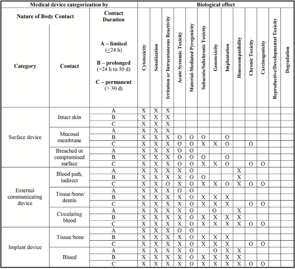
The ISO 10993 standard addresses the need for a biological evaluation of medical devices. This standard was developed to eliminate the potential biological risks associated with the use of a medical device, and is extremely important for our device to comply with, due to the nature of our device and its close contact with the human body. Depending on the nature of body contact and the duration of that contact, a medical device will be expected to conduct different biocompatibility tests to ensure safety to the patient and/or user. Body contact is categorized as a surface device, an external communicating device, or an implant device. Each of these categories have subcategories specific to the tissue in contact. The contact further divides these subcategories into limited contact (A), prolonged contact (B), and permanent contact (C).
Our device would most likely fall under tissue/bone for the external communicating device category. The THA surgical procedure typically takes place for 1-2 hours, so our device would be under limited contact (A). Therefore, our device would have to be able to prove it has been successfully tested against cytotoxicity, sensitization, and irritation. The FDA also recommends consideration of acute systemic toxicity and material mediated pyrogen testing.
Lyons, J. (n.d.). Biocompatibility testing for medical devices: “the big three”. Eurofins – Medical testing. Retrieved April 18, 2022, from https://cdnmedia.eurofins.com/european-west/media/1925430/9415-mdt-biocompatibility.pdf
Manufacturing
There are a handful of considerations to be made when considering the manufacturing process and how it has impacted the design selection for the Smart Hip Broaching System. To start, the broaching equipment (the mallet and broach handle) will have the sensor system embedded within the device. The sensors will be located within the head of the surgical mallet and within the broach handle close to the broach locking interface. To be able to embed the device into the surgical equipment, the smart sensor system must be minimalistic and take up as little space as possible. To minimize the size of the smart sensor system, a custom circuit board will be designed and manufactured, and an Arduino Nano board will replace the current Arduino Uno board to reduce the size of the sensor system by ½.
Additionally, the broaching equipment will be wireless and the sensor systems will be embedded within the device to allow the smart broach handle and smart mallet to be sterilized post-surgery the same way other THA surgical equipment are – via steam sterilization. A few design considerations must be made to ensure the Smart devices can be sterilized this way. For example, the stainless-steel mallet and broach handle will need to be waterproof and able to withstand the steam sterilization process. We need to ensure that there will be no small holes, obscure geometries, or crevices in the design to make cleaning easier.
In our design process, the team was looking to build a prototype with wireless transmission. However, we did run into software issues with this bluetooth prototype so this may be a prospect for the future. We purchased a 4-Pin Wireless Bluetooth Transceiver Module that will allow the device to both send or receive the TTL data via Bluetooth technology without connecting a serial cable to a computer. This will eliminate the need for direct connection to a computer in the operating room which will minimize interference of our system during THA. The bluetooth chip would be placed inside the mallet and broach handle with a battery to power.
Testing
For future testing, it is important to characterize the amount of force needed to impact into different bone qualities and set thresholds for maximum allowable forces. This, however, is part of phase 2 of the project as it will require cadaver testing and clinical trials with experienced surgeons to perform broaching to characterize the bone quality.
An additional test that should be performed as part of phase 1, however, is determining the accuracy of the sensors. The objective of this test would be to ensure that the sensors are actually picking up the right accelerations and that the force calculations are accurate by comparing the calculated force values to a measured force value. This test could not be completed in time due to lack of a functional impaction force load cell to measure the impact force. Thus, if this project were to continue, this would be the next test to be done.
Acknowledgements
We would like to express gratitude to all individuals who have supported us throughout our project. We’d like to thank our supervisor Dr. Lee, and our TA Stephen Wells, for their continuous support and guidance in all aspects of our project. We would like to thank Dr. Lerner and Dr. Seidman for helping us source materials and providing meaningful feedback on our assignments, prototypes and demonstrations. We thank our customer Dr. Ginnetti in allowing us to further our knowledge by shadowing a hip replacement, and providing us with the necessary tools to create our prototype and conduct testing. We express gratitude to Drew Miller and Heather Zukas, from Johnson and Johnson, Jarrod Orszulak, from Everight Position, and Chris Pratt, from the University of Rochester Mechanical Engineering Department, all of whom have provided professional advice to aid us in navigating our way toward success in creating the smart hip broaching system.