Team
- Max Moskowitz
- Melanie Almenas
- Alison Peyton
- Eric Wang
Mentors
Robert Minckley, David Lambert
Abstract
The purpose of this project is to build anatomically accurate Jaekelopterus 3-ft and 9-ft structures. Using the program NX, the structures were modeled, and a CNC machine code was generated. The pieces of the structures were cut using the CNC machine. These pieces were glued together, and putty, spackle, and paint were applied. To create a dynamic 9-ft structure, proposed mechanisms were created and finalized, and are ready for future teams to implement and build. Suggestions for future work to minimize the cost of production and increase efficiency are also included.
Problem Statement
There is a lack of awareness of the fascinating research conducted in Hutchison Hall. In celebration of Hutchison Hall’s 50th anniversary, the Biology Department wants to install a physical representation of the type of research they undertake to educate the public and increase the building’s appeal.

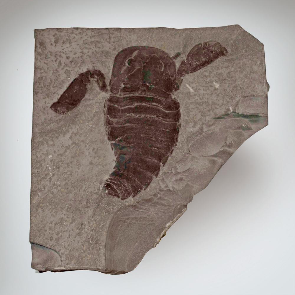
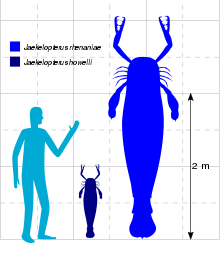
What is a Jaekelopterus?
The Jaekelopterus is a genius of eurypterids (yer-ip-ter-id) or sea scorpions. They used to swim in shallow seas across the globe over 400 million years ago. This became the New York State fossil in 1983 due to the abundance of these rare fossils in Buffalo, NY. The Jaekelopterus is also the largest known eurypterid to have ever existed.
Requirements
- There must be mounting hardware with cables at 3 points of contact in a triangle formation. The location of each point of contact depends on the pose of each structure.
- The dynamic structure’s tail must be visibly able to move.
- All three structures will be made of the same material and manufactured using the same methods, but each will be in a distinct swimming pose.
- The structures must be anatomically accurate to the Jaekelopterus.
- The dynamic structure must move its claws and tail when triggered by a stepper motor.
Specifications
- The cables attached to the connection points in unison will hold the structure’s weight with a factor-of-safety of 10.
- To test the factor-of-safety, an object equaling the structure’s weight times the factor-of-safety will be hung up with the cables at a lower (specified) distance from the ground with (specified) material as a cushion on the ground below. The cables must hold the weight without dropping the object onto the ground.
- The weight of each structure cannot exceed 300 pounds.
- A crane scale will individually weigh the structures to ensure they are under the maximum weight.
- The dynamic structure must connect to the building’s wall using 110 volts for power.
- A multimeter will be used to measure the electrical connection in the wall and verify a 110 volts distribution.
- The dynamic structure must connect to the building’s wall using 30 amps for power.
- A multimeter will be used to measure the electrical connection in the wall and verify a 30 amps distribution.
- The total cost of completing the deliverables must not exceed $1000.
- The money spent on the project will be tracked to prevent overspending.
Deliverables
- A 9-foot-long, anatomically accurate Jaekelopterus structure that is static in a swimming position.
- A 3-foot-long, anatomically accurate Jaekelopterus structure that is static in a swimming position.
- A 9-foot-long, anatomically accurate Jaekelopterus structure that is static in a resting position until it is triggered to move its claws and tail.
- A written report detailing all elements of our final deliverables and analysis, manufacturing information, and an evaluation of our success.
Concepts
| Pugh Matrix for Material | ||||||
| Material | Complexity | Durability | Safety | Price | Novel | Total |
| ABS Plastic | 0 | 0 | 0 | 0 | 0 | 0 |
| Carbon Fiber | -1 | +1 | -1 | -1 | +1 | -1 |
| Foam | 0 | +1 | 0 | -1 | +1 | +1 |
| Pugh Matrix for Method to Trigger Motion | ||||||
| Mechanism | Complexity | Durability | Safety | Price | Novel | Total |
| Button | 0 | 0 | 0 | 0 | 0 | 0 |
| Motion Sensor | +1 | 0 | 0 | -1 | +1 | +1 |
| Timer | 0 | 0 | 0 | -1 | +1 | 0 |
| Adding to Building’s Light Circuit | -1 | +1 | -1 | -1 | +1 | -1 |
Complexity – Will using this idea lengthen or shorten the manufacturing process compared to the baseline?
Durability – Will this idea allow the mechanism to have a longer lifespan than the baseline material?
Safety – Can this idea hurt manufacturers or product users? (Ex: is it flammable or does it emit toxic fumes when working with it)
Price – How does this idea’s cost compare to the baseline idea?
Novel – Is this idea new or obtainable compared to the baseline?
Based on the Pugh Matrices, the decision to use the motion sensor to trigger motion has been made because it is the least complex, most safe, and a novel idea when compared to the baseline. The material chosen is foam because it is durable, safe, and a novel idea when compared to the baseline.
Mechanical Analysis
The body of the Jaekelopterus structures is derived from an existing scanned, 3-ft Jaekelopterus model. The model is scanned using the FARO arm pictured in Figure 7. The scanned file is uploaded to the CloudCompare software. This software provides the tools necessary to read the text file provided by the FARO arm, orientate and decimate the image, and segment the imagine into manageable sections in a process called cloud point manipulation. Next, the cloud file is uploaded to another software named Bentley Pointools PODcreator, which converts the cloud file to a POD file that can be used in the NX software. Once on NX, the 3D model is uploaded as a reference point cloud. The model is divided into three segments: the torso, head, and tail. These segments are created individually and later combined as an assembly.
Figure 7. Professor Muir scanning the 3-ft model with the FARO arm (top) and the results of the scan (bottom)
The torso is first made by tracing the cross-section of the 3D image using the Spline feature, as shown in Figure 8. Then, the 3D shape is modeled in sections using the NX Realize Shape feature. This 3D modeling process involves molding sheets, using The Realize Shape feature in NX, into the form of the scanned image. Using the Extrude feature in NX, a solid shape is created. The torso is modeled as two separate parts to account for the CNC process described later in the Manufacturing section. The torsos for the 3-ft and 9-ft structures are modeled differently. The 3-ft structure is a direct copy of the swimming position of the scanned model, illustrated in Figure 9.
Figure 8. The sketch of the torso using the Spline tool
Figure 9. The NX 3-ft structure bottom (left) and top (right) torso
The 9-ft structure uses the same processes stated above, illustrated in Figure 10, but is made symmetrical to create a different swimming position to fulfil the requirement. Additionally, the segments on the 9-ft structure are made slimmer than the 3-ft structure to reduce manufacturing time.
Figure 10. The NX 9-ft structure bottom (left) and top (right) torso
The head, like the torso, is designed in NX using the scanned pointcloud model. The model is used as a reference when creating sketches for the outline of the head. Sheet bodies were used to create the shapes for both the head and the eyes, as seen in Figure 11. The head is designed symmetrically to increase speed and efficiency when cutting using the CNC machine. A top and bottom head is created, Figures 11 and 12 respectively. The bottom head piece was only used for the 3-ft structure because it was determined to be unnecessary for the overall shape of the head, as the legs covered the bottom of the head.
Figure 11. NX 3-ft and 9-ft structure top head
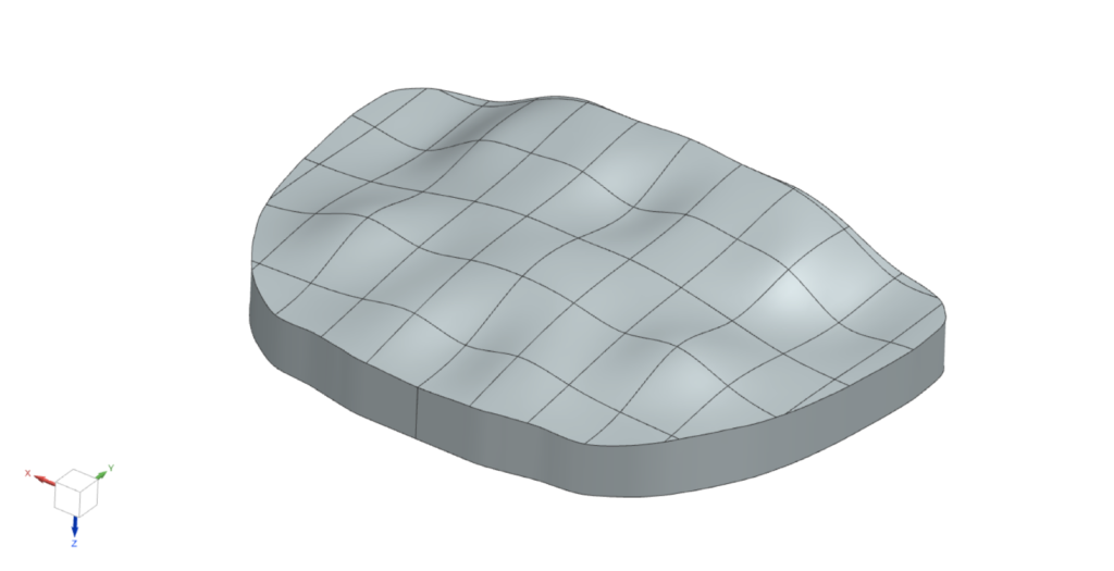
Figure 12. NX 3-ft structure bottom head
Using the same techniques as the torso and head, point cloud models are assembled from the Jaekelopterus scans. The tail is created separately from the body for better visualization. The design of the tail is created using the Realize Shape tool in NX. The tail is divided into a tail tip part and a tail shell part. The tail tip is created using a block and two spheres with the Realize Shape tool. The regional thickness of the block is adjusted to align with the thickness of the tail. The spheres are then assembled onto the block in the correct locations, referencing the 3D scanned model. An outline of the tail tip is sketched using NX, Figure 13, from the point cloud model.
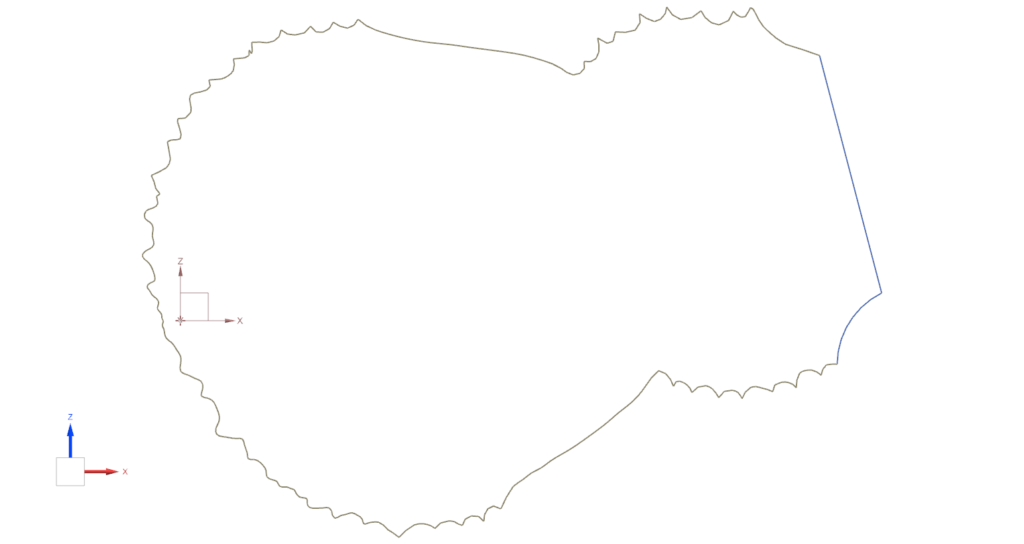
Figure 13. Sketch of the tail tip outline
Finally, the tail tip outline sketch is extruded and used to trim the Subdivision body from the sheet body. For the tail shell, four cylinders are created with step-down dimensions and the geometries of the cylinders are manipulated using the Transform Cage tool. Figure 14 shows three images; the first image is the scanned tail model used for the point clouds, the second is the final geometry of the tail shell created with sheet bodies in NX, and the third is the final geometry of the tail tip, also created using sheet bodies in NX.
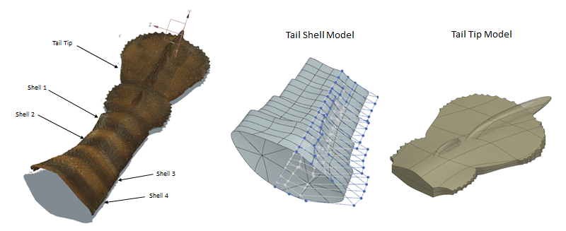
Figure 14. 3D Scanned tail model; Tail shell model; Tail tip model
Once the individual pieces are created and assembled into one model, Finite Element Analysis is conducted. This analysis is used to determine the location of the cable connection points on each structure as well as the potential weight of the 9-ft structure. The model is meshed in NX using 3D Tetrahedral mesh with a size of 20, as shown in Figure 15.
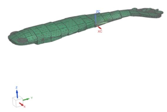
Figure 15. A meshed, 3-ft structure assembly without the claws, legs, and fins
The location of the cable connection points, and potential 9-ft structure weight is found using the Solid Properties Check feature. This feature gives relevant information, such as the volume and center of mass of the assembly. These properties are shown in Figure 16.
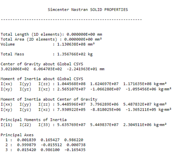
Figure 16. The material properties of the 9-ft structure after meshing
The center of mass will be used in future work to locate three connection points on each structure. The claws, legs and fins are not included in the Finite Element Analysis since they were not made using the CNC machine and are calculated separately. The specification of having three connection points has not been fulfilled due to the sponsors deciding to hold off on adding the cables until future teams create the dynamic structure. However, this analysis will be used as reference for the future teams.
The weight of the 9-ft structure is calculated using the volume and density values of the foam used for manufacturing. The added weight of other materials applied to the structure, such as the putty and paint, are estimated using the 3-ft structure as reference. These calculations are described in Table 5.
Table 5: Weight Calculations (not including limbs)
| Volume [m^3] | Foam Density [kg/m^3] | Weight based on Model (foam alone) [lb.] | 3-ft structure weight of Putty/Paint [lb.] | Scaled up 9-ft structure weight (foam + paint/putty approximation) [lb.] |
| 0.113064 | 24.8 | 6.2 | 4 | 20 |
These calculations help fulfill the specification of creating a large structure that is less than 300 pounds. Once the structures are completed, they will be weighed to verify these findings
Manufacturing
The Jaekelopterus structures consist of the main body parts, the head, the torso, and the tail, along with the leg parts. The main body parts are fabricated using a CNC machine. A CNC machine can efficiently create the shape of the structure with simple programs in NX. Compared to other manufacturing methods such as 3D printing or injection molding, CNC manufacturing is more cost-efficient and a better fit for large-scale fabrication. Since the Jaekelopterus structure has rounded edges and the CNC machine only supports translations, the body parts are cut in half along the center line to minimize any overhang during fabrication. Once the CNC program is complete in NX, high-density foam is cut to the correct size of the NX bounding body and the material is attached to the platform to prevent movement. Some of the CNC pieces can be seen in Figure 17.
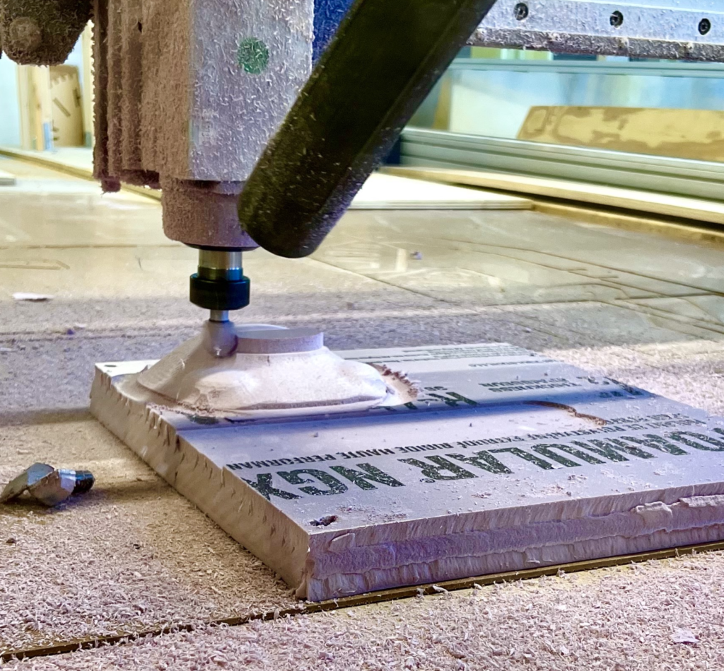
Figure 17. (top to bottom) The CNC machine cutting the 3-ft structure head, the 9-ft structure top torso, and the 9-ft structure tail
For the 9-ft structure, the CNC programs are simplified to minimize producing time, and therefore partially reduces accuracy. Therefore, sanding is required to improve the texture of the structure. When building the 3-ft structure, the pieces are layered with putty to create a protective shell. Once the putty is dry, it is sanded to create a smooth finish. Any remaining holes are filled with spackle. After finishing the 3-ft structure, the decision was made to skip this step for the 9-ft structure since the sanding was difficult and time consuming. Instead, the 9-ft structure pieces are layered with spackle to fill the gaps in the insulation foam, as well as creating a protective layer around the foam. This improves the smoothness of the surfaces, making it easy to paint.
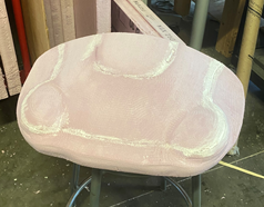
Figure 18. (top to bottom) The 9-ft structure top torso covered in spackle; the gaps in the 9-ft head filled in with spackle; the bottom of the 3-ft structure covered in both putty and holes filled in with spackle
The 3-ft claws of the Jaekelopterus structure are manufactured by 3D printing. 3D printing allows for more detailed manufacturing compared to the CNC machine. However, there they are constrained by limited space inside the printer. Another reason 3D printing is used is because the spikes on the claw make it complicated for CNC manufacturing. After the claw is 3D printed, it is covered in putty so the paint can be applied later to create a uniform look compared to the rest of the structure.
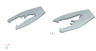

Figure 19. The NX model of the claws (top); the 3D printed claws covered in putty (bottom)
The 3-ft structure legs, fins, and arms of the claws are created by wrapping wooden dowels in construction paper, applying putty, and sanded down for a smooth texture. After sanding, paint is applied. The unpainted legs and fins can be seen in Figure 20.
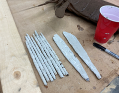
Figure 20. The legs and fins of the 3-ft structure covered in putty and sanded
The 9-ft structure legs are created by cutting a corrugated drain hose into 18-in pieces. Triangles are cut out at one end of the hose and the sides of the triangle are glued together to create thinner ends. Putty is applied to the hose to fill in the ridges. Once the putty is dry, the legs are sanded, painted, and attached to the 9-ft structure.
Table 6 contains the estimated manufacturing time for the two static structures. The 3-ft structure takes roughly 52 hours to produce, and the 9-ft structure takes approximately 64.5 hours. Among all operations, the legs took the longest time to manufacture, and the second longest time was taken to prepare for the CNC machine. At a flat rate of $100 per hour, around $12,000 is spent to manufacture the two structures.
Table 6:
Table 7 estimates the hours for each team member in the concept development and mechanical analysis phase. In contrast to the manufacturing time, almost 700 hours were spent designing and performing analysis on the structure. Assuming a flat rate of $100 per hour, $69,200 is spent solely in the development period, with an overall project cost of $81,173.
Table 7:
If the system were to be scaled to 1000 systems, the following operations would be improved to minimize cost of production and to increase efficiency:
- Injection-molding will be used to create the legs, fins and claws. Since the legs, fins and claws have irregular geometries, injection molding allows the manufacturer to produce multiple pieces at once without hand building or sectioning the pieces into halves. This increases the efficiency of the leg, fin and claw production by at least ten times, meaning one leg, fin or claw can be created in under one hour.
- Generalizing the size of the pre-CNC materials will be used. In this project, insulation foam boards were purchased at The Home Depot with a dimension of 2-in by 4-ft by 8-ft. Therefore, for some of the parts, such as the torso and the tail, it was necessary to resize the material into smaller pieces and glue them together prior to fabrication, which is time consuming. If 1,000 pieces of the Jaekelopterus were produced, the size of the bounding body in NX would be generalized and the material from the suppliers would be ordered with the same dimensions.
- During manufacturing, the CNC machine was coated with pieces of high-density foam due to the static electricity. There were multiple times when the roller of the CNC machine was jammed, causing the program to shut down. A solution would need to be determined to remove the static charges on the CNC machine in the future. Another option would be to use materials that do not conduct electricity such as wood and plastic.
Test Plans and Results
A cable test was conducted to verify that the attached cable connections would hold the structure’s weight within the given factor of safety. This test was a modification of the original testing plan and was approved by the sponsors. The University of Rochester Facilities will provide cables of a specified maximum load. The purpose of this new test was to determine the maximum weight required for an eyebolt to slip out of the foam. This modification proved to be more relevant to our safety considerations. Three, 1 ½-in pieces of foam were stacked on top of one another with a 10-in long, ½ -in diameter eyebolt through the center. A 1-ft by 2-ft wooden board was placed on top of the layers and connected using the eyebolt. To prevent the eyebolt from slipping through the foam, a 2-in washer was placed on top of the wooden board and a 2-in by 2-in metal plate was placed at the bottom of the foam layers. A rope was attached to both ends of the wooden board and connected to a plank with a roller underneath. The purpose of this system was to allow a person to push the foam down with their body weight as they walked across the plank. To measure the added weight, a crane scale hung from a staircase and was attached to the eyebolt.
The maximum weight applied in this test was 160 lbs. At this weight, the foam did not slip out from the bolt. It was determined that 160-lbs was an adequate limit since the 9-ft structure will have three of the same eyebolts, amounting to 480 pounds. Based on the calculations described in the Analysis, the structure would likely be significantly less than that amount, even with a large factor of safety. It was concluded that this test passed the specification.
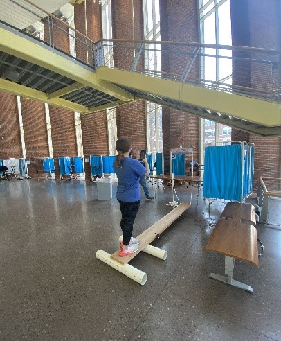
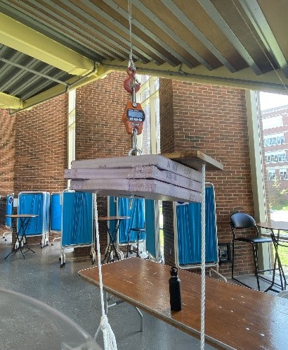
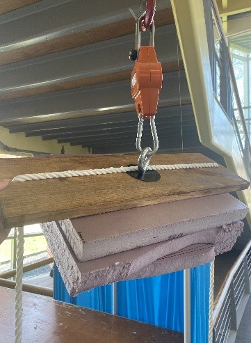
Figure 21. (top to bottom) A team member standing on the plank system for adding weight; a front view of the cable testing system; a top view of the testing system .
Intellectual Property
nce most of this project was done by using a CNC machine through traditional methods, most of the process and techniques used are not patentable. Large anatomical models of organisms are also not a new product or concept, dating back to ancient Greece. Eventually via trade routes, animal modeling soon became a research tool of both European and Arab physicians. [2]
Societal and Environmental Implications
The societal impact of this project is that Hutchison Hall will be viewed as a more welcoming space. More students may want to study biology due to the building’s increased appeal. The environmental impact is that the structures will be assembled and mounted without damaging the building or the surrounding environment.
Recommendations For Future Work
This project involved many aspects and processes that would have been time-consuming if all original specifications and requirements were met. The mechanisms alone were projects by themselves. If more time was given to work on the project, the mechanisms would be prioritized for the 9-ft dynamic structure. The original proposal of the project also included a drivable robotic model which also is a project by itself. However, it would not take priority over the 9-ft dynamic structure and the mechanisms. If another future senior design group picks up the pieces of this project that were not able to be finished on time, it is recommended that they utilize what has already been created in terms of the mechanisms and CNC code for the structures. This would allow for the future group to accomplish the mechanisms in a timely manner. It is also recommended that the future group should plan further ahead and make a strict schedule so that objectives will be met in a timely manner. This was something that this team struggled with at first, but improved as the semester progressed. Another recommendation for this project is to model all parts of the body as soon as possible so the mechanisms can be worked on.
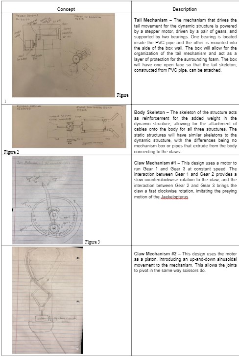
While the dynamic structure is no longer a requirement for this project, an analysis was conducted on the tail mechanism. The mechanical system pictured in Figure 22 was created to meet the requirement of having a tail that could visibly move. The system consists of both a small and large driven gear that is connected to a shaft. The shaft has a mounted bearing at one end, with a ball bearing between it and the t-connector PVC pipe. The t-connector pipe is attached to a 1-ft PVC pipe that will move the foam tail. The drawings for the box that housed this system can be found in Figure 26, Appendix A. A stepper motor would drive this system. A dynamic analysis was completed to determine the appropriate stepper motor for this application. Each of the components were assigned as moving bodies, and joint connections were made to simulate their actual movements. Additionally, the material properties of each component were included in the analysis for more accurate results. The driver gear acted as the driver in the simulation that allowed the 1-ft pipe to move in an arbitrary, up and down motion. The result of this simulation is shown in Figure 23, where the holding torque of the mechanism is plotted.
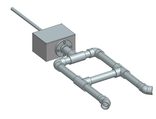
Figure 22. Two orientations of the dynamic PVC pipe reinforcements attached to the box that houses the tail mechanism
Figure 23. A close-up of the tail mechanism (top) and the plotted results of the dynamic simulation (bottom)
The holding torque is needed to compare with the specifications of the potential stepper motor. Using this information, it was determined that a NEMA 23 stepper motor is required to drive this system. This mechanism can be improved to reduce the weight added to the structure and the cost of the motor. A smaller torque would require a lighter, less expensive motor. One way to reduce these values is to support the middle of the 1-ft PVC pipe as it moves. The pipe acts as a cantilever beam, so adding a support would transfer stress and load away from the end where the stepper motor is connected. A smaller stress and load decrease the holding torque and allows for a less powerful motor. This would in turn cut back on costs and added loads.
Another future accomplishment that can be achieved is the mechanism of the claws. As mentioned previously, the final design for the claw mechanism requires a linear driver, shown as an arrow pointing in the Y-direction in Figure 24. Pin 3 only allows rotation around the X-direction. Pin 1 and Pin 2 allow for translation only, whereas Pin 4 allows for both translation and rotation. The linear driver provides translation on the end of the structure, causing the long bar to pivot around Pin 3. A trace of the motion generated from the NX simulation is shown as the blue crosshairs on Pin 1.
Figure 24. A NX representation of the claw mechanism simulation.
Concept Development and Deliverables
Design Description
Manufacturing Video
Future Work
Acknowledgements
We would like to thank Professor Robert Minckley and Professor David Lambert for sponsoring this project. We also thank you Professor Christopher Muir and Jim Alkins for their invaluable guidance throughout this project.