Project Overview
Abstract
The Secondary Mirror (SM) of an optical space telescope is supported by three struts with ends that attach to the Forward Metering Structure (FMS) of the telescope. Such secondary mirror support structures (SMSS) are found on various satellites, including the James Webb Space Telescope and WorldView-4 Earth remote sensing satellite. Presently, 3D metal printing is not the conventional manufacturing method for satellite applications. For the WorldView-4, graphite composites are used for the mainstream production of satellite parts like the SMSS because of its lightweight and high strength properties. In this project, however, our team explored the practical applications of a 3D metal printed SMSS, designed using a topology optimization tool and structurally analyzed by using the finite element method (FEM). Given a mass goal and loading conditions, the stiffness of the structure was optimized. The rationale behind this research is both economical and geopolitical. The demand for spacecraft is growing each year, which necessitates the need for faster and cheaper manufacturing methods like 3D metal printing. This report reviews the concept generation, finite element analysis (FEA), fabrication, and testing methods involved in constructing an SMSS prototype for our customer, L3Harris Technologies. The resulting design passed all requirements.
L3Harris Overview

About L3Harris:
L3Harris is an American technology company, defense contractor and technology service provider that produces are variety of commercial technology across land, air, sea, cyber domains, and space. Moreover, L3Harris delivers solutions from start to end to provide customers with mission critical requirements and specifications. L3Harris is rank 163rd on Fortune 500 rankings of the largest United States based companies.
Problem Definition & Statement

Problem Definition: Reflector telescopes are a type of optical telescope assembly (OTOptical Telescope Assembly (OTA) metering structures such as Secondary Mirror Support Structures (SMSS) are time-consuming and costly to manufacture with traditional manufacturing methods.
Problem Statement:
A space telescope cannot be repaired most likely if a component fails after launch. As a result, every single component, including the SMSS, is mission critical for the success of a space telescope. Moreover, during launch, all components of the telescope are exposed to extreme vibrations, thermal loads, and accelerations. Traditionally, SMSS for space telescopes were manufactured with composites due to their low densities. Currently, the Optical Telescope Assembly(OTA) metering structures such as SMSS, are time-consuming and costly to manufacture with traditional manufacturing methods. For these reasons L3Harris is trying to utilize metal 3D printing because of its high potential solution for producing reliable and relatively inexpensive SMSS.
Requirements, Specifications, and Deliverables
Requirements
1) The project scope is the design, analysis, and prototype of the Secondary Mirror Support Structure (SMSS) only (hosted hardware masses and interfaces are provided for reference and use in finite element models, etc.).
2) L3Harris requests that this project focus on additive manufactured (3D printed) solutions to the problem. L3Harris is currently working on a 3D printed invar (desirable due to low CTE) but invar is not a requirement for this project.
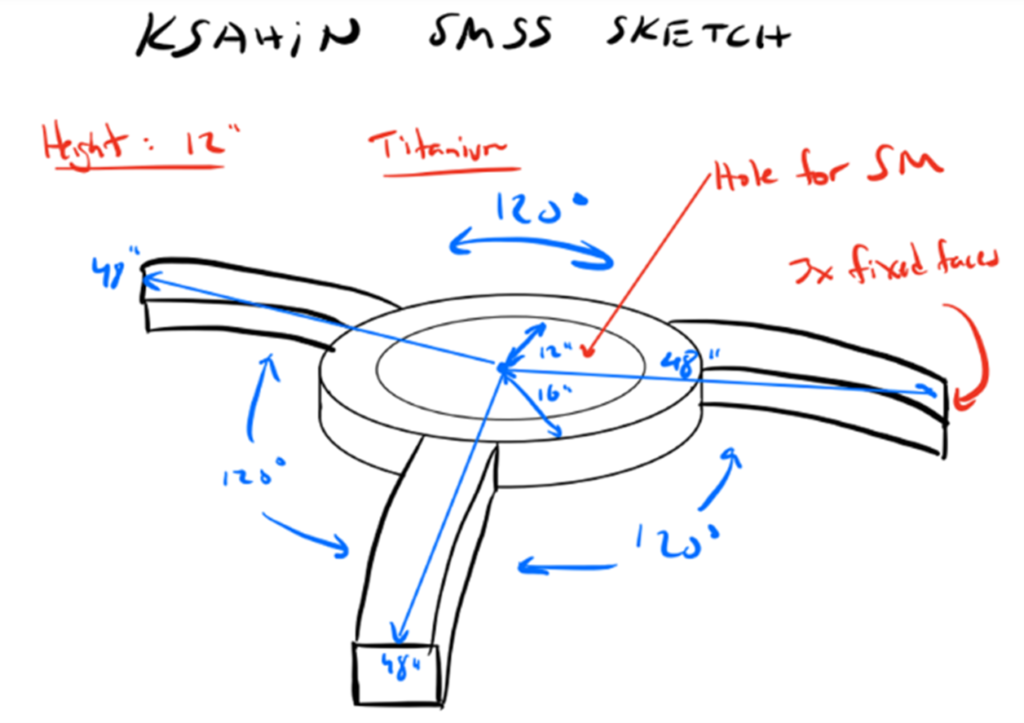
3) The SMSS shall interface to the Forward Metering Structure (FMS) at three locations 120 degrees apart.
4) The SMSS shall provide interfaces for and support the following hosted hardware (Secondary Mirror and Mounts, Actuator Assembly, Shade Assembly, Misc. Thermal Hardware) – see MICD for detail.
5) Design (CAD model geometry) shall be producible with additive manufacturing methods (3D printing).
6) There shall be no trapped cavities.
Specifications
1) The outer diameter of the SMSS (interface to the FMS) shall be 48 inches.
2) The first mode of the SMSS shall be 120 Hz or greater when grounded at the FMS interface and supporting all hosted hardware.
3) SMSS Mass: Goal is 18lbm.
4) The SMSS shall have positive margins of safety against yield and ultimate failure when exposed to a quasi-static load of 12 G laterally and 18 G axially simultaneously (lateral swept 15ºC increments) combined with a 5ºC to 35ºC temperature range (nominal room temp is 20ºC) while supporting all hosted hardware. (nominal room temp is 20ºC) while supporting all hosted hardware.
5)The SMSS and hosted hardware shall not obstruct more than 14% of the PM clear aperture area
6) The structure must be able to support the weight of the 23lbm of hosted hardware (secondary mirror, baffle, actuator plus additional dead weight – not in CAD model).
7) The following design factors of safety shall be used in the analysis (if applicable):
Yield: 2.0
Ultimate: 2.5
Composite: 2.6
Buckling: 4.0
Bond 3.0
8) The following mass contingency factors shall be used (if/where applicable)
Concept design: 20%
Preliminary design: 15%
Final Design: 10%
Post-Final Design: 5%
Measured hardware: 0.10%
9) The SMSS should provide a stable mounting platform for the Secondary Mirror (SM) in thermal environments. The average motion of the SM interfaces under a 1ºC isothermal load should be 0.66 micro-inches translation (RSS of X and Y) or less and 0.037 micro-radians rotation (RSS of Rx and Ry) or less.
Deliverables
1. CAD file prototypes using NX (step file format) and 2D drawings.
2. Finite Element Model (FEM) in Nastran.
3. Final design report.
4. Host design review meetings and provide supporting slides and drops of the CAD and FEM: Concept Design Review, Preliminary Design Review and Final Design Review.
5. 3D printed prototype (can be scaled and from the material of choice).
6. Reports on any model validation – could be included in design review slides and final report.
Concept Ideas
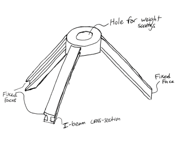
Concept I- I-Beam Cross Section Structure
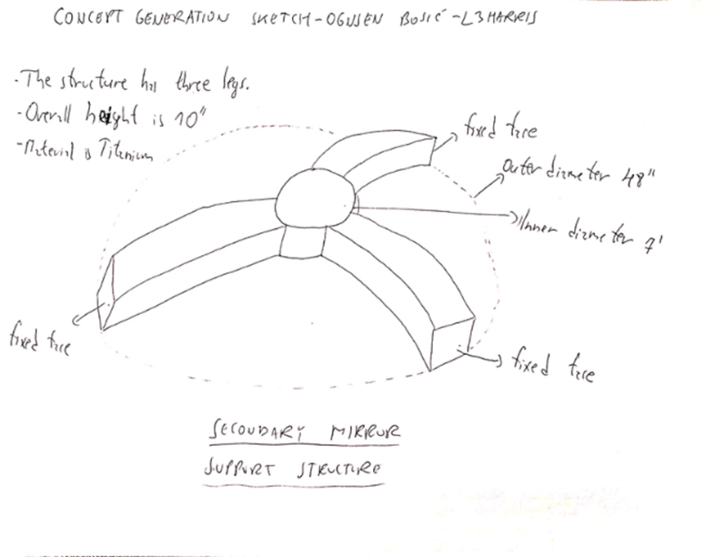
Concept II- Solid Center Structure
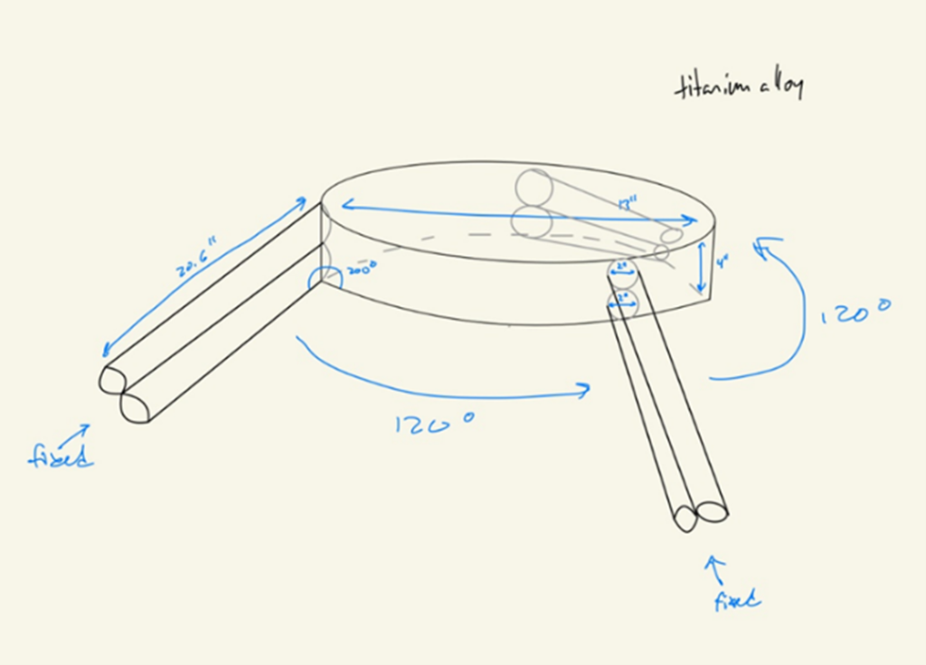
Concept III- Double Cylinder Structure
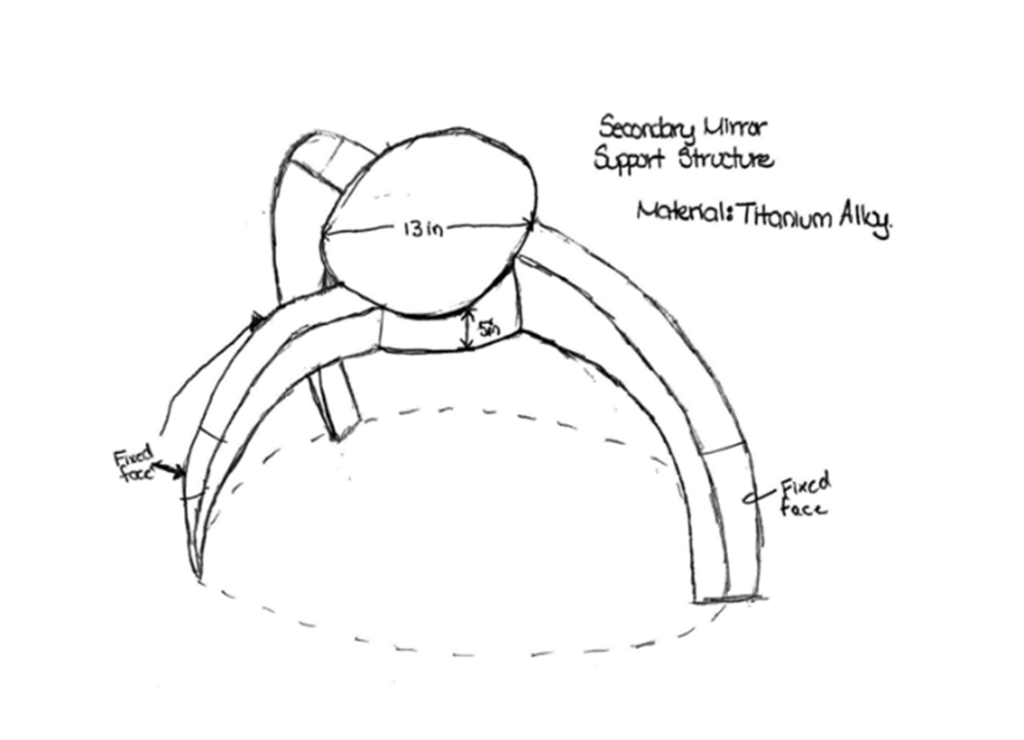
Concept IV- Tapered Support Leg Structure
Concept V- Doughnut StructureModel Optimization
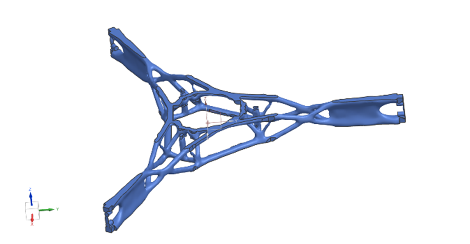
Topology optimization is the principal modeling method chosen for the final SMSS design. Siemens NX, the primary CAD software used for this project, decided the final geometry mathematically. The result of the topology optimization given is shown to the right. The team gave the optimizer tool a given set of loads and directions for those loads, as well as boundary conditions. These included the gravitational loads required by the sponsor and fixed constraints that represent the mounts of the structure as explained in the Requirements, Specifications, and Deliverables section. The optimizer’s assigned objective was to maximize the stiffness while attaining the target mass of 18lbm and not surpassing 50% of the yield strength of Ti-64. However, the optimizer itself cannot be relied on for producing the most reliable results, as topology optimizers consist of many approximations during calculations, including linear approximations for stiffness equations, and curve-fitting onto voxel-based geometry to produce smooth surfaces. Moreover, the geometry of the model had to be fixed to get rid of useless or somewhat concerning protrusions in the model.
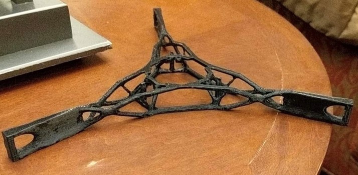
Manufacturing
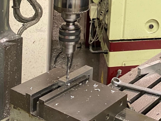
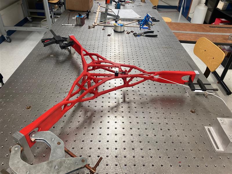
The entire model was designed on Siemens NX, and manufactured using 3D printing. The model was assigned Titanium for online simulations and 3D printed in ABS-M30 at a 60% scale. Before printing the 60% percent model, the team also printed a 20% scaled-down version of the design to be printed. The printed 20% model showed the printability of our finalized structure at a small scale. For testing, aluminum 6061 supports were manufactured and pressfit pins were used to connect them to the model. The supports were produced from an L-shaped aluminum block and a bandsaw was used to cut out 3 support brackets. Lastly, a load plate was produced for vertical and horizontal displacement testing.
The table below, shows the artificial cost of the project.
| 3D Printing | |
| 20% Reduced Model | $200.00 |
| 60% Reduced Model | $600.00 |
| Load Plate | $450.00 |
| Pin Testing Block | $67.00 |
| Insert and Bolt Test Block | $134.00 |
| Lattice Blocks | $1,000.00 |
| Plastic Dowels | $5.00 |
| Machine Time | |
| Mounting Legs | $1,000.00 |
| Team’s Total Cost ($100/Hr.) | $76,650.00 |
| Total Cost of Project | $80,106.00 |
Mechanical Analysis
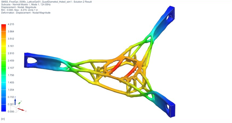
Some specifications required mechanical analysis. Analysis on this project was conducted through NX NASTRAN software, which involved running two different types of simulations. These simulations were used to determine the first mode of the structure, maximum stresses experienced, maximum displacements and the buckling modes. Data was then compared to the results obtained through testing.
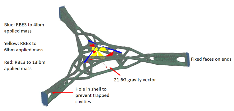
The first picture is the FEM of our design with references to the simulation test set-up.
One of the simulations was the modal analysis for which NX Solution 103 Real Eigenvalues was used. This helped the team acquire the modal frequency data and compare it to the desired 120 Hz. For modal simulations, no loads were applied, but boundary conditions were set. This meant that the faces at the ends of the structure were all fixed, but neither gravity nor the thermal loading were applied.
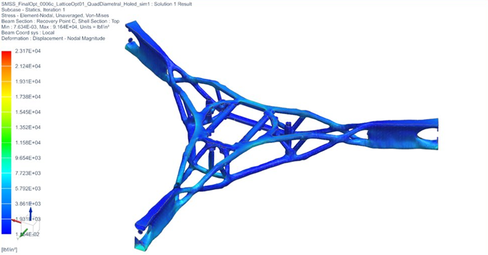
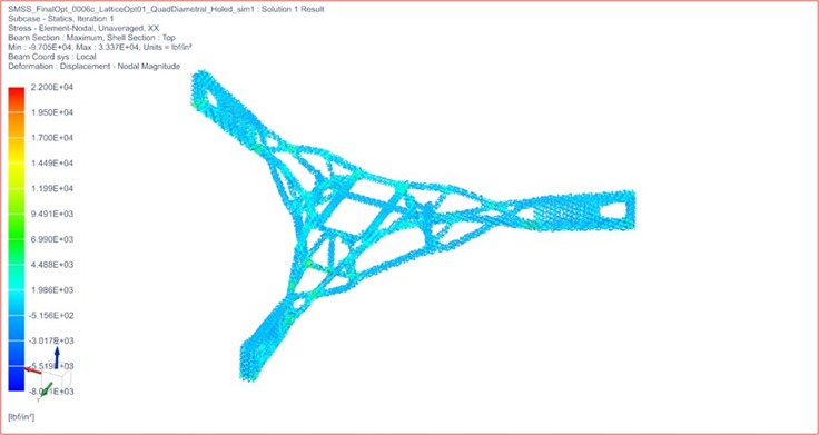
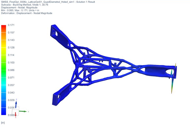
The other simulation was the NX Solution 105 Linear Buckling. This simulation allowed the team to understand where areas of high stress and displacement are and their magnitudes. It also provided the buckling modes of the structure. In addition to setting boundary conditions, for the Solution 105 simulations, all loads described in the specifications section were applied.
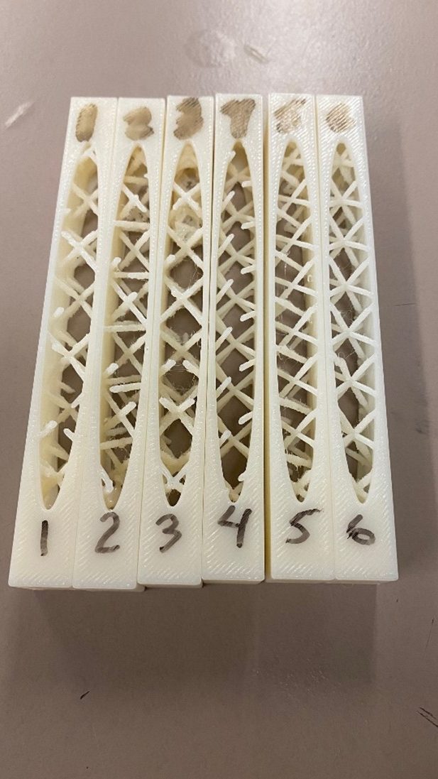
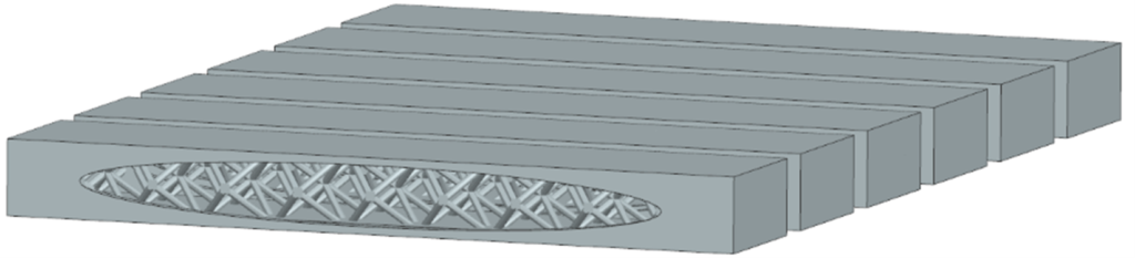
Lattice Testing
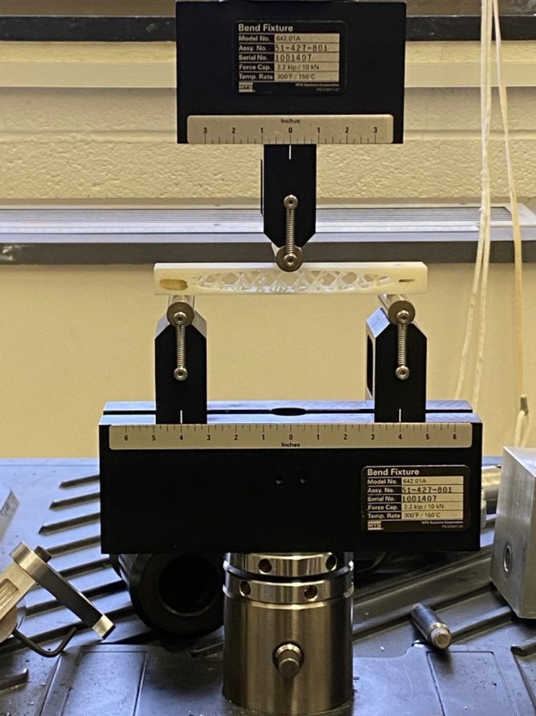
To test which lattice structure performs best, a bending test was conducted. The standard procedure is to secure a block at an equal and set distance away from the cylindrical supports. The bending test was conducted at the Mechanical Engineering building using an MTS (Material Test System) machine. The flexure fixture was attached to the machine and the extensometer to read the displacement of the lattice block. The flexure fixture places increasing weight to the structure, the MTS machine recorded the force and the displacement of the block, and the data was recorded and analyzed. From the data, the stiffness of the lattice structure can be obtained and our team was able to analyze which lattice structure was optimal for our design.
Test Plan & Results
A few physical test were done along with multiple test on the Siemens NX simulation. Specifications 1 and 3 were easily met using physical tools. Specification 4, used NX to test the model and then a simple displacement test was used on our physical model.
The displacement test was conducted on the 60% scaled model. The printed design was placed on a Newport table, supported by the aluminum mounting legs and a magnet at each end of the mounting legs, and the displacement test was recorded using a height gauge.
For the vertical displacement test, the height gauge was placed directly above the SMSS structure at a point between two SM mount holes. The loading plate was hung loosely with six M5 bolts and loads were added to the plate. From this test, the force over displacement results correspond to the SMSS’s overall stiffness in the direction of the load when applied at the center point of the structure. For the horizontal displacement test, the masses were attached to a pulley system and the height gauge was placed horizontally between the SMSS’s legs.
A modal strike test was also conducted on the 60% scaled structure. The accelerometer on the moving mass of the shaking body, captured the first mode of vibration in the vertical direction. Before testing began, the data acquisition software was calibrated using a stroboscope. The modal test results for the scaled model found a natural frequency of 66 Hz, which was substantially lower than the expected result of 140 Hz based on the simulations of the same 60% model.
Of the test done on Siemens NX, Specifications 2 and 6 both meet the requirements, however different lattices and different 2D mesh sizes can change the numbers quite drastically. Specification 5 discussed that the SMSS and its hosted hardware, including secondary mirror, actuator assembly and shade assembly, shall not obstruct more than 14% of the primary mirror clear aperture area where sunlight would pass through. The topology optimized model obstructed approximately 12% of the PM. This value was calculated by creating a 2D sketch plane on the top view of the SMSS model in NX, then creating splines surrounding the figure to subtract the enclosed areas from the area of the solid body. The hosted hardware shadow was included in the calculation, while the hole in the PM was not considered in this calculation.
| Specification | Result | Requirement | Result | |
| 1 | Satisfied | 1 | Satisfied | |
| 2 | Satisfied | 2 | Satisfied | |
| 3 | Satisfied | 3 | Satisfied | |
| 4 | Satisfied | 4 | Satisfied | |
| 5 | Satisfied | 5 | Satisfied | |
| 6 | Satisfied | 6 | Satisfied | |
| 7 | Satisfied | |||
| 8 | Satisfied | |||
| 9 | **multiple results |
| Requirement | Full-Scale Simulation Result |
| Max Stress: 49000 psi | ~23000 psi |
| 14% obstruction | ~12% |
| 120 Hz | 124 Hz |
| Buckling (SF = 4.0) | ~30 |
| Mass: 18lbm | ~9lbm |
| *Micro Yield: 0.66 µin RSS translation | 14.9 µin |
| *Micro Yield: 0.037 µrad rotation | 0.72 µrad |
| 60% Simulation Result | Test Result |
| Vertical Displacement: 0.0028″ | ~0.013″ |
| Horizontal Displacement: 0.000055″ | ~0.0015″ |
| 140 Hz | ~60 Hz |
Societal and Environmental Implications
Pros:
- 3D printers are efficient and high precision when creating objects
- 3D printers are not to costly to purchase
- Additive Manufacturing decreases the amount of wasted material
- Topology Applications utilize lattice structures in designs to further decrease the use of unnecessary material that will not affect a design’s structural integrity
- New jobs in the 3D printing field will open/be available in the upcoming years (such as 3D printing engineers or technical support jobs)
- 3D printing has the ability to rapidly produce objects
- Opens more opportunities for advancement in astronomy and satellite imaging in general
Cons:
- The carbon foot print of 3D printing is much larger than traditional manufacturing methods
- Increases the amount of energy waste compared to traditional manufacturing
- Typically uses plastics which are not biodegradable, which increases plastic waste
- The popularization of 3D printing will put manufacturers out of work
Conclusion
3D metal printing is likely a viable and more affordable alternative to composites for an SMSS. Moreover, our final design did pass all of the specifications and requirements given by our sponsor.
Recommendations for Future Work
If given the opportunity to work on this project for another six months our team would make a few changes. Firstly, we would have printed our design with a lattice instead of a solid infill. Our team experienced many problems with the NX software when meshing the shell and the lattice and the CAD file would not work. With the help of Professor Muir, revised our model and applied a 2D mesh in the FEM to work as a shell, then began simulating different internal lattice structures.
If given more time, our team would test each lattice structure given from NX and our own designed lattices. This also means that we would have approximately 25 different simulations per lattice (24 different applied gravity loads and a modal simulation). This would take over 20 hours of testing per lattice and this is not even considering complex lattice structures. Complex lattice structures are structures that cannot be printed without support structures due to large overhang angles, which would decrease the printability of the design.
A Taguchi design of experiments (DOE) study could also be conducted if there was more time and resources available. The DOE would require the use of several factors, such as lattice type, lattice rod thickness, and 2D shell thickness. Each factor would have at least three levels. The team already explored different lattice types and shell thicknesses, but not in the context of DOE. To evaluate each of the experiments, a response would need to be defined by the team.
Our team would also want to print a full-size metal version of our final design in Ti-64, but our budget did not allow us to do so. The cost of 3Dmetalprinting our design in full scale would cost approximately $45,400.00, far more than the $1,000limit we were given. If our team was able to print a metal version and a plastic version of our design and test each design’s structural integrity, it would have been a better indicator of whether our design would fit inside the specifications of the telescope and would have been a more accurate representation of how our design will work when tested. Moreover, with more time our team would conduct thermal testing to confirm material properties such as CTE. Finally, if given all the time we need, we would want to mount the structure onto a satellite and launch it deep into space, if L3Harris validates our model and deems it a valid optimized solution.
Final Design Report
Authors
- Rachel Anthony
- Ognjen Bosic
- John Luby
- Joseph Rodziewicz
- Kadir Sahin
Mentor
Patrick Ellsworth
Acknowledgements
The team would like to thank Professor Muir of the Mechanical Engineering Department at the University of Rochester, for helping our team troubleshoot problems with the NX software because of the complexity of our design. Also, for helping our team use the FaroArm for measurements and for the help with the vibration testing set-up.
We also want to thank Jim Alkins for his advice about 3D printing and for 3D printing test blocks for our team.
We would also like to thank Omar Soufan for providing our team with screws, inserts, and washers.
We want to thank Chris Pratt for helping with the bending test and for helping us order our 60% 3D printed model.
And finally, we would like to thank our sponsor Patrick Ellsworth for his help throughout our weekly meetings and for the opportunity to work with L3Harris.