Team
Theo Taylor – Project Coordinator
Ryan Szymczyk – Primary Zemax Simulator
Max Greenberg- Scribe
Customer

Customer Contacts
Marco Smarra and Athul Som
Faculty Advisors
Professors Wayne Knox, Ed Herger, and James Zavislan
Project Vision
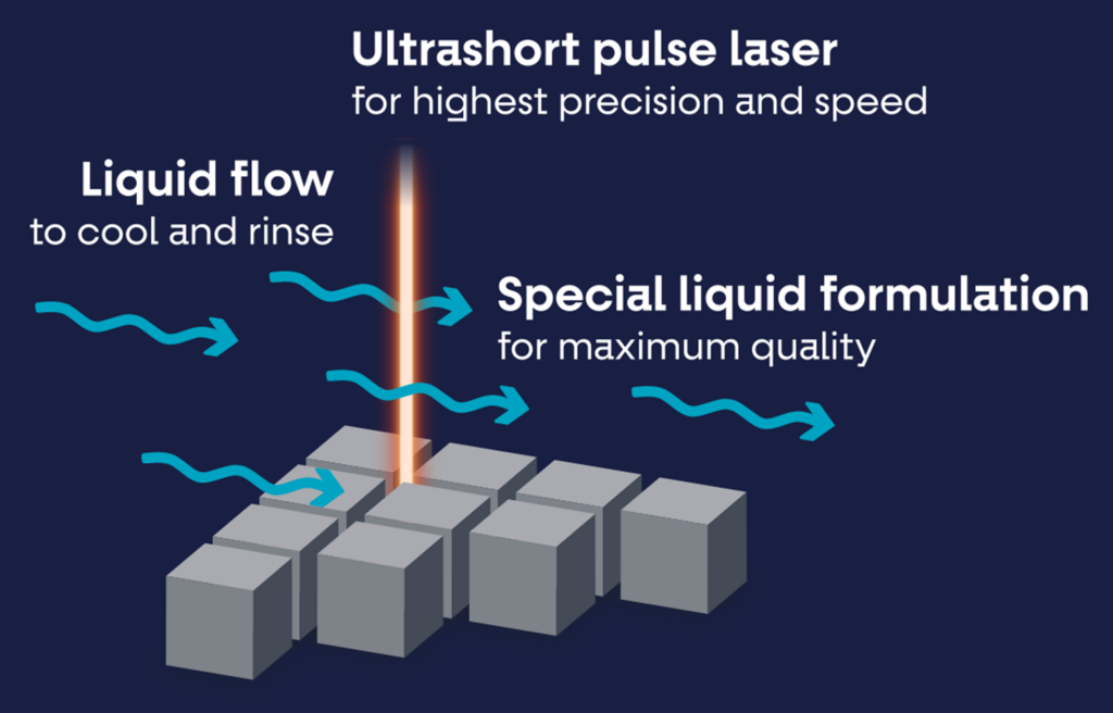
Lidrotec manufactures laser dicing machines for the semiconductor industry. These machines are used to cut various materials, including silicon wafers, and can produce cleaner cuts than previous technologies while also reducing material stress and chipping. They would like us to design an adjustable focus shift module that would allow their laser cutter to focus at different z-axis positions at the workpiece within a small range while still allowing for their current x-y scanning capabilities. This would enable better cutting performance of variable thickness materials and avoid having to move the entire laser system along the z-axis as they do now.
The Current System
Lidrotec’s current system consists of a laser beam that is passed through a specialized beam shaping module, a beam relay, and a scanning lens that is able to adjust the focus of the beam across the surface of the workpiece in the x and y directions. Luckily, Lidrotec is in the process of constructing a new system, so we have leeway in our packaging constraints and do not have to fit our design perfectly within their current architecture.
Our Solution
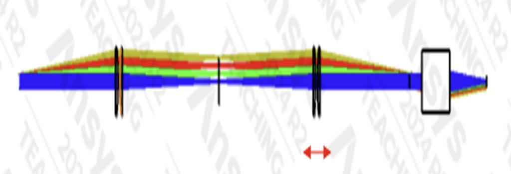
To achieve the desired focus shift, we proposed making the position of the second lens group of the beam relay adjustable along the optical axis. Shifting this group with a translation stage allows us to shift the focal position of the laser beam on the workpiece.
We performed optical simulations to determine which optical and mechanical components we would need to best meet Lidrotec’s goals, while keeping prices as low as possible. Ultimately, due to Lidrotec’s beam size, we settled on using custom optics for a larger clear aperture.
Testing
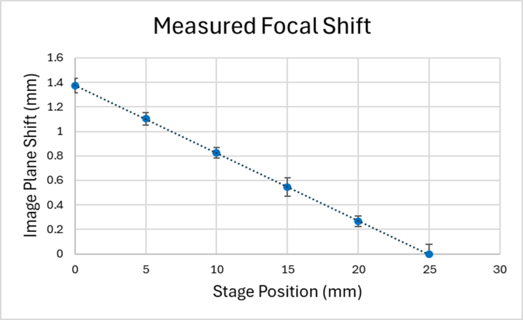
To verify our simulation results, we recreated a simplified version of the system with using 1” optics and a motorized translation stage to test the correlation between element displacement and the shift in focus position. To measure the focal position, we use a camera mounted on an adjustable translation stage.
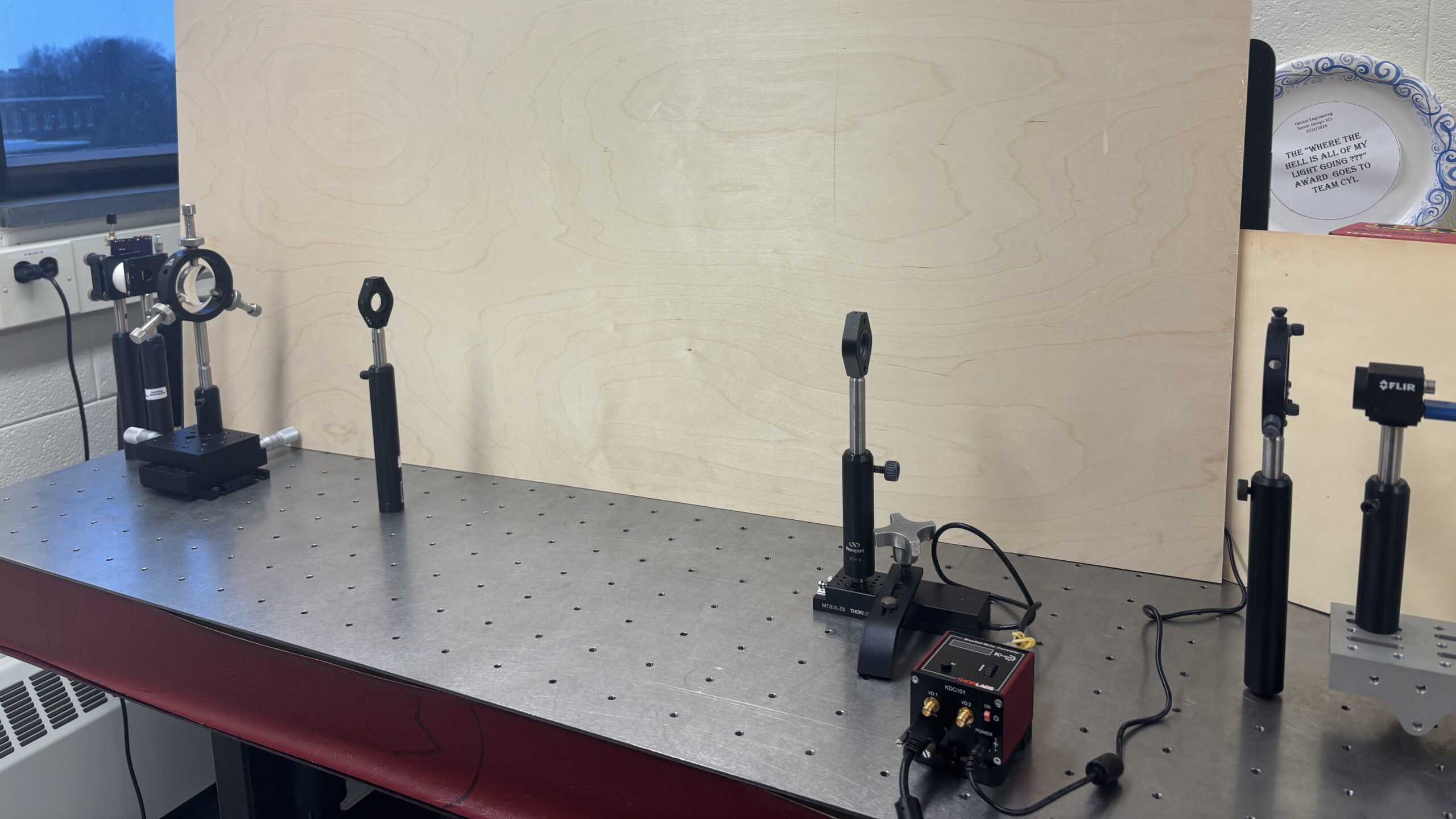
By imaging the beam at multiple positions, we can determine the beam waist as a function of position and back out the focal position where the beam is tightest. Repeating this process at multiple lens element locations allows us to correlate the element displacement to focal shift.
Conclusion
Once our simulation results are fully verified with laboratory testing, Lidrotec plans to order the larger custom optics along with a translation stage as prescribed to implement our focus shift solution.
This will allow their system to achieve the desired focus shift and easily adjust that parameter between cuts. This way, a greater variety of silicon wafers, including those with variable thicknesses, can be processed without reduced performance.
Thank You!
Special thank you to our company contacts Marco Smarra and Athul Som at Lidrotec for working with us this semester.
We also want to thank professors Knox, Herger, and Zavislan for their help considering and executing different testing plans.