Team Members
- Bryan Burke, Electrical and Computer Engineering ’25
- Madison King, Electrical and Computer Engineering ’25
- Gina Wang, Electrical and Computer Engineering ’25
Mentors
- Professor Jack Mottley
- Professor Dan Phinney
- Professor Irving Barron Martinez
Introduction
Our team designed a line of sign communications system that sends text messages between two devices using infrared lasers. The system utilizes Arduinos which send a Pulse Width Modulated signal between them. It allows users to enter their own 32 character messages using the provided keypad or choose from one of three preset messages.
Hardware
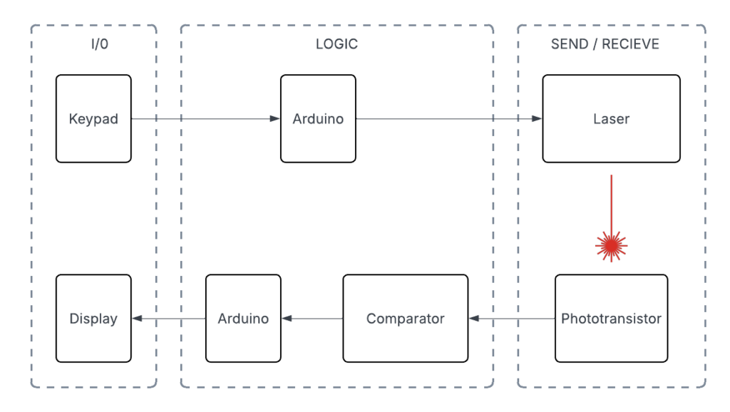
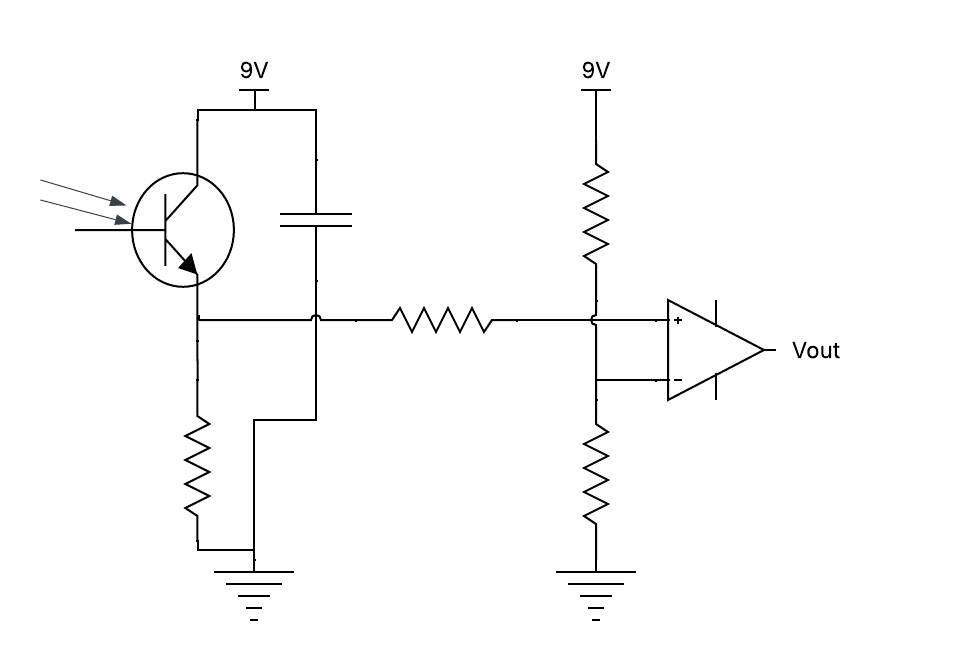
Data is entered through the keypad before it is translated by the sending Arduino microcontroller to a train of pulses, which the laser sends. The pulse train is detected by the phototransistor a few feet away. However, the phtotsensor’s output is very small, necessitating the use of a comparator in this design, which boosts the signal to a level where the receiving Arduino can interpret the data. From there, the message is displayed on the LCD display.
Software
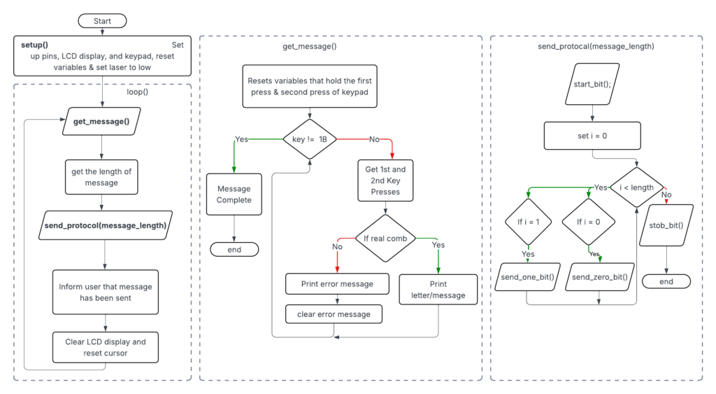
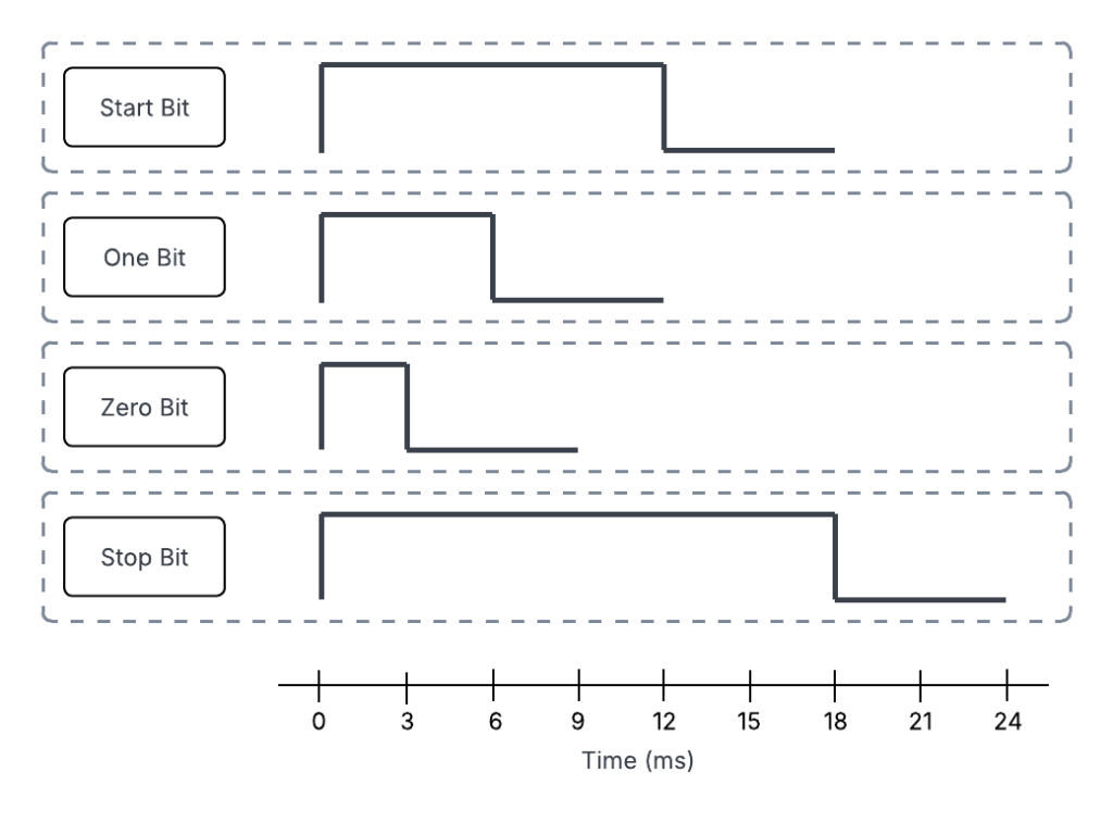
The sending code interprets keypad inputs, where every 2 presses of the keypad corresponds to one character. The message will be displayed on the screen as the user enters it. Once the user confirms the message, the message is sent as a Pulse Width Modulated signal to the receiver. This signal contains a start bit followed by 6 bits for each character and then ends with a stop bit.
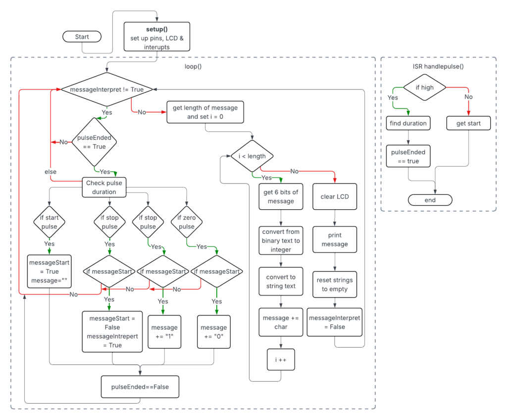
The receiving code utilizes conditional logic with an interrupt that triggers when the signal changes. It analyzes the pulse duration to determine what pulse was sent. Once a message is completely received, it decodes the binary string to display the final message to the user.
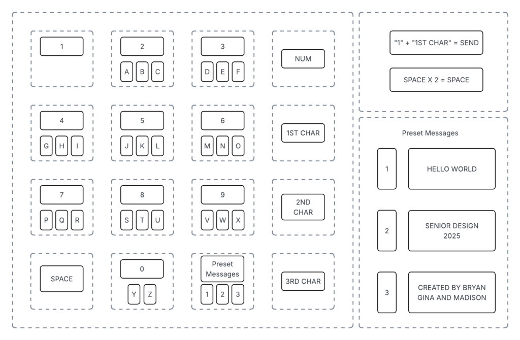
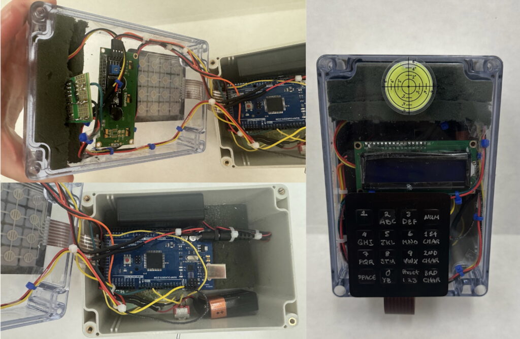
On the keypad, each button contains 1 number and 3 letters that are selected using the buttons on the far right column. In order to send the message, the user must select the “1” key followed by “1st Char.” There are also three pre-programmed messages available for the user to select. In order to select one, the user should select the “Preset Messages” button followed by the char button which corresponds to the message they would like.
Demo Video
Future Recommendations
If continued work was done on this project these are the improvements that we would like to see made.
- Improving the Range: In order to improve the range beyond 5 ft. there must be a way to better align the laser beam or limit the beam spread. A higher power laser could be implemented as well.
- Faster Data Transmission: This would require a different laser with a faster switching speed to keep up with higher frequencies. It would also require the code to be modified to work at the microsecond scale.
- Adding Voice Transmission: Additional hardware and software, specifically an ADC and DAC, would be required along with much higher switching speeds for successful voice transmission.
Acknowledgements
Thank you to professors Jack Mottley, Dan Phinney and Irving Barron for their help and support while creating this project. We appreciate the technical expertise of Paul Osborne and Kyle Ohlschlager.