Abstract
The objective of this senior design project is to improve sealing to reduce internal valve leakage across output ports of a rotary style 3-way / 2-position coolant control valve without significantly increasing motor actuation torque. An existing design, as well as requirements and specifications, were provided as a starting point by G.W. Lisk, a worldwide supplier of valves, solenoids, LVDT sensors, and other precision components for various military and commercial industrial applications. Throughout the semester, the team came up with several different design concepts. Through the use of a Pugh matrix and concept selection criteria, two designs were selected for further design optimization and testing. The team created CAD of the two designs in order to conduct various computer-based analyses. The two designs were manufactured and assembled into prototypes. A test plan was formulated for both on-campus testing done by the students in order to measure leakage and actuation torque and for official testing at Lisk facilities. The on-campus testing found a leakage reduction of more than 90% compared to that of the baseline design and an acceptable actuation torque for both prototypes. These initial testing results were further confirmed by official testing at the G.W Lisk facilities.
About the Company
Headquartered in Clifton Springs, NY, G.W. Lisk is a worldwide supplier of valves, solenoids, LVDT sensors, and other precision components for a number of different military and commercial industrial applications.
Project Description
Problem Statement
Coolant is needed to decrease the temperature of batteries in electric vehicles. It is desired to have a 3 way / 2 position motor operated rotary coolant valve to direct flow at different times to the batteries and a bypass system. The current baseline design contains leakage across the output ports of the valve. Improved designs must minimize this leakage without significantly increasing actuation torque.
Requirements
- The valve assembly must be able to provide a pathway for the coolant (50/50 glycol and water mixture);
- The valve must connect to a motor that can provide actuation torque;
- The valve must have 1 inlet and 2 outlet ports. Outlets must be 180 degrees opposed. 90 degrees between the inlet and the two outlets;
- Stay away from ferrous materials or anything that is not compatible with the coolant solution mentioned above;
- Mounting hole configuration is to remain intact to current layout;
- There is to be no evidence of leakage past exterior sealing interfaces.
Specifications
- Pressure drop is maintained within 5% of 50 kPa;
- Inlet and outlet pipe diameters are within 2% of 1 inch;
- The leakage rate target is 10% of the baseline (1.4 L/min);
- Actuation torque must not exceed 1.2 Nm. If higher torque is required to achieve internal leakage requirement, defense of rationale will be required for acceptance;
- Valve gate must rotate within a 90-degree (+/- 2 degrees) range between outlet ports;
- Valve does not have structural failure due to thermal stresses between –40 ˚C and 125 ˚C.
Provided Valve Housing
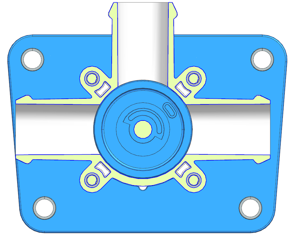
The image to the left shows a top down cross section view of the outer valve housing supplied by G.W. Lisk. The inlet is the pipe that extends from the top of the image and the two outlets are the pipes that extend to the left and the right of the image. Different gate concepts were designed by the team to spin inside of the value housing and block the desired outlet to minimize leakage.
Design Solutions

Design 1

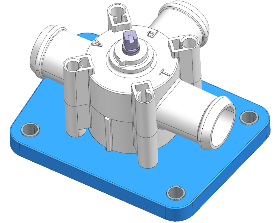
Explanation: A press fit (part 3) on the shaft (part 2) extends compression springs (part 4) to keep two flaps (part 1) in place against the outer valve housing. The gate base (part 5) is inserted into the bottom of the valve housing. When in front of an outlet the pressure differential across the valve forms a seal between the flap and rim of the outlet pipe. A top down view of Design 1 inside the valve housing can be seen in the motion simulation below.
Colloquial terms for each part:
1: Flaps
2: Shaft
3: Press fit component
4: Springs
5: Gate base
6: Spring caps
Additional Design 1 Information: Tolerance analysis was completed between parts 2 and 3 in order to create a press fit for the motor to transmit torque through the shaft. The springs are made out of corrosion resistant materials to increase the lifespan of the design. Ultra High Molecular Weight Polyethylene (UHMWPE) was selected as the material for the flaps due to its flexibility and low surface roughness. The notches on the flaps constrain them to the gate while it’s rotating. The spring caps (part 6) and the extending cylinders on part 3 form a slider joint to constrain the compression springs to 1 degree of freedom. Flap thicknesses of 3/32″ and 1/16″ were chosen for testing and analysis.

Design 2

Explanation: A gate (part 1) inserted onto a shaft (part 3) contains two cavities that each hold a flap (part 2). The gate is inserted into the bottom of the valve housing. When in front of an outlet the pressure differential pushes the flap towards the outlet to create a seal between the flap and rim of the outlet pipe. A top down view of Design 2 inside the valve housing can be seen in the motion simulation below.
Colloquial terms for each part:
1: Gate
2: Flaps
3: Shaft
Additional Design 2 Information: Like Design 1, UHMWPE was selected as the material for the flaps due to its flexibility and low surface roughness. The gate was 3D-printed with Polylactic Acid and sanded to decrease the coefficient of friction between the gate and valve housing. This allows the motor to turn the gate with less torque. The thickness of the flaps was designed to be greater than the distance between the gate and valve housing. This permits the flaps to remain in their cavities while the gate rotates to prevent possible jamming. Flap thicknesses of 3/32″ and 1/16″ were chosen for testing and analysis.
Simulation
To test the validity of Designs 1 and 2, several computer-aided analyses were conducted.
Flap Notch Interface
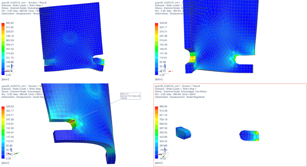
The above figure depicts stress analysis on the notches of the flaps due to the friction load exerted by the valve housing. The purpose of the simulation is to verify that the maximum stress in this region will not cause the flap material, UHMWPE, to fail. The top left corner shows an exaggerated simulation of the flap and gate when the load is applied. The top right and bottom left corners are two different perspectives of the flap to display the locations of stress concentrations. The bottom right corner shows the stress profile on the protrusions on the gate. The results show that the maximum stress occurs at the edges where the two surfaces interact, which is expected. The maximum stress of interest on the flap is 330 psi and the ultimate tensile strength of UHMWPE is 3550 psi, which gives a factor of safety of greater than 10. Therefore, the design of the flap is validated and does not need modification.
Contact Pressure
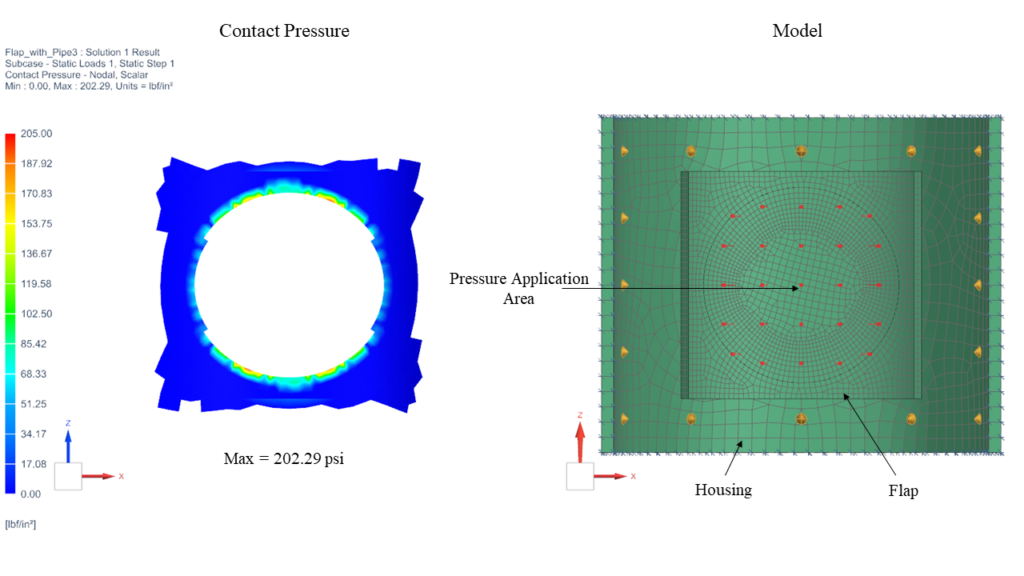
For Designs 1 and 2 the team expected the pressure differential between the inlet and outlet to cause the flap to slightly deform and create a seal when in front of an outlet. To test this idea the team created a simulation to analyze the contact pressure around the rim of the outlet. The figure to the left shows the results of contact analysis between Design 2 with the 1/16” flaps and the valve housing. The relatively complete pressure profile shown on the left side of the figure demonstrates that the design is feasible. The same simulation was completed for Design 2 with the 3/32″ flaps and for Design 1 with both flap thicknesses. Their simulations produced similar promising results and can be found in the team’s final project report located near the bottom of the website.
Flow Visualization
As seen in the video above, the team used computational fluid dynamics to visualize fluid flow through the valve when one outlet is fully blocked. Although velocity is depicted in the video, the simulation also provided insight into pressure drop and pressure distribution throughout the valve. Further explanation into the team’s pressure findings can be found in the team’s final project report located near the bottom of the website.
Manufacturing
The team decided to use Ultra High Molecular Weight Polyethylene (UHMWPE) as the material for the flaps in Design 1 and 2, due to its compliancy and very low friction. The UHMWPE flaps were purchased from McMaster in sheets of 5 ft with varying thicknesses. The manufacturing of the flaps was done in two stages. The first stage, only applicable to Design 1, consisted of milling two notches on both sides of the flaps (see the left figure below). The second stage consisted of bending the flaps at 130°C using a mandrel to achieve the correct curvature (see the right figure below).


Components including Design 1’s press fit, gate, and spring caps, and Design 2’s gate were all 3D-printed with Polylactic Acid (PLA) due to their organic shape. The team considered machining the components from round stock but decided that machining would be time consuming, costly, and a waste of material. Ideally, the team would have injection molded these parts for the tightest tolerances but mold design is time consuming, expensive, and outside the scope of one semester of work.
Testing
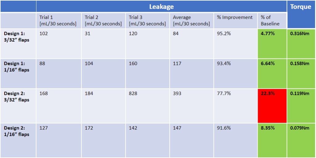
Testing at the U of R
On-campus testing was completed by the team in order to compare the leakage and actuation torque of Designs 1 and 2 to that of the current existing model from Lisk. Water was used rather than coolant for safety and environmental reasons. Pictures, a video, and results from testing are seen below.


U of R Test Results
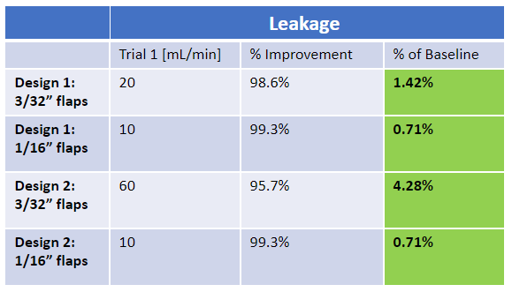
Testing at Lisk
For more rigorous testing and with the proper coolant solution, the valve hardware was sent to G.W. Lisk testing facilities. The results of these tests are seen below.
Lisk Test Results
Presentation
Project Report
Meet the Team!
Students

Front to Back:
- Peter Schaefer
- Harris Mawardi
- Yixin Pan
- Xin Liu
- Hanne Hartveit
Mentors
- Dan Meath
- Troy Rutherford
- Trevor Crandell
Acknowledgements
This project was supported by G.W. Lisk Co Inc. We thank our mentors from G.W. Lisk Co Inc, Dan Meath, Troy Rutherford, and Trevor Crandell for all the insight and assistance they provided from years of industry experience.
We are also grateful to members from the University of Rochester, including Christopher Muir, Christine Pratt, Jim Alkins, Marc Haddad, and F. Douglas Kelley, for the continuous support and critique they provided in their areas of expertise. This project would not have been possible without them.