Authors
- Blake Curlee
- Chenhao Jian
- Justin Sennyondo
- Weihan Wang
Mentors
Prof. Christopher Muir (Supervisor)
Prof. Ethan Burnham-Fay (Sponsor)
Seungju (Jamie) Yeo (Assigned Teaching Assistant)
Abstract
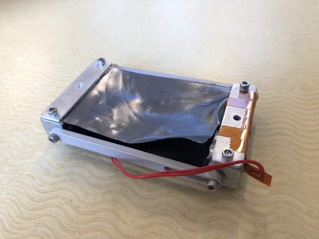
The ME 205 LLE Cryogenic Heat Pipe Team designed a new version of cryogenic heat pipe for a high-energy laser system at the University of Rochester Laboratory for Laser Energetics (LLE). The design is composed of three major parts: the collar, the clamp, and the strap connecting the collar and the clamp. The testings of the new heat pipe have produced useful data, based on which our group can give suggestions for future development of the heat pipe.


Problem Statement
A mechanically robust thermal pathway is needed to transfer heat from the target to the cryocooler for a high-energy system in the University of Rochester Laboratory for Laser Energetics (LLE). It is part of a subsystem that is usually closed and only retracts to expose a target to a high-energy shot by the OMEGA laser. The heat pipe is necessary for providing a pathway that is flexible enough to retract while also conducting heat away from the target to the cryocooler to maintain the target at cryogenic temperatures (about 10 – 20 K) before the laser shot. The original heat pipe design at LLE uses pyrolytic graphene sheet (PGS) for the strap, which is a flexible material with excellent thermal conductivity, but is also very fragile. Thus, the major goal of this Senior Design project is to design and/or recommend material(s) to be used for a heat pipe that will not break or tear easily as the present one does.

Requirements
- Transfer heat from the target capsule to the cryogenic pump
- Must not break or tear easily (flexible)
- Work in a vacuum environment at cryogenic temperature
Specifications
- Able to transfer heat without failure at temperature of 60 +/- 5 K
- Minimum thermal conductivity of 125 W/(m*K)
- Maximum displacement transmissibility of 0.1
- Minimum failure load of 5 N
Design Concepts
- Based on LLE baseline [1] and Technology Applications Inc.’s Thermal Straps [2]
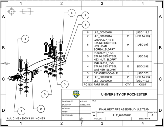
- C10100 Copper used for Collar, Clamp, and strap fittings
- Cryogenic cable used for straps [3]
- Stainless steel bolts
- Originally, stainless bolts used to contain heat from explosive bolts
- Considered using explosive bolts to eliminate vibration effect, but cryogenic cable was flexible enough, so there was no need for explosive bolts.


Manufacturing
- Bought copper C10100 block and sheet, stranded copper (SC) cryogenic cable, stainless-steel bolts, nuts and washers.
- Machined the clamp, collar and strap fittings using the bandsaw and vertical mill along with an edge-finder, the given end-mill, a spot drill, a number 31 (0.120 in. diameter) drill bit, hand-drill, among other tools.
- Cut the cryogenic copper cable into small cables and removed the outer plastic jacket at the ends to better stack the cables between the strap fittings. Indium foil was then added for improved thermal contact.
- The nuts, bolts and washers were used to fit the parts into one cryogenic heat pipe assembly.
- Estimated system manufacturing cost is $15,992.98, including the purchased-items ($642.98) and the team members’ Siemens NX development and analysis time ($10,450) plus building time ($4,900).
- If 1000 such heat pipes were to be made, manufacturing costs could be reduced by buying material of the desired thickness to lower machining time.
Analysis


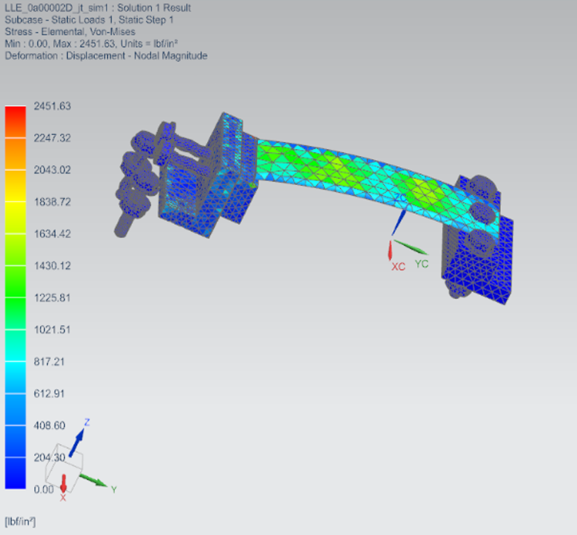
These initial analyses showed high thermal resistance across the clamp; minimal stresses in typical operation and favorable thermal properties overall.
A tolerance analysis was also performed to find the minimum and maximum diameter for the holes and bolts as well as the 3σ upper and lower limits of the nominal gap between the stacked cables and the 2 holes on each strap fitting. All parts were determined to assemble and fit as intended.
Testing
Thermal Test
- A thermofoil resistive heater was attached to one of the system powered by a current and voltage source. Aluminum foil and foamed plastic were used for thermal insulation.
- A four-channel DAQ and thermocouple were used to determine the temperature difference at the collar and clamp ends, with data recorded in LabVIEW.
- A liquid nitrogen bath was later used (but without the heater) to simulate a close-to-cryogenic environment.
- Minimum 1 hour was required to reach steady state. Output file reading, plot making and data analysis were all done in MATLAB software.
- The measured temperature difference was then used to calculate thermal conductance.
- A Siemens NX thermal simulation was also done for verification of results.

Vibration Test
The cables were approximated as a spring, and the equivalent spring constant was found by measuring its force and its displacement. Then, the heat pipe was simplified as a spring-mass system, whose displacement transmissibility can be found by the following equation, where x0 is the exciting amplitude, X is the response amplitude, r is the normalized frequency, and ζ is the damping ratio (assume ζ=1):

The results show that the natural frequency of the heat pipe is only 6.648 Hz while peak vibration from cryo-cooler is at about 282 Hz. The energy being transmitted through the heat pipe with transmissibility of higher than 0.1 is less than 0.4% of the total vibration energy from the cryo-cooler. Therefore, it’s safe to concluded that the vibration effect of the heat pipe is trivial.

Load Test
The heat pipe was attached to a force gauge. The heat pipe sustained over 10 N of force (2.5 lbs) without failure.

Evaluations and Conclusion
- Passed the thermal conductivity specification because the value from the FE simulations is at least 225 W/mK. From the physical testing, thermal conductivity could not be measured due to the unknown shape factors and other difficult-to-determine thermal variables for the considered geometry. Only the thermal conductance could be calculated.
- The physical tests, however, gave the temperature variation at the ends and elsewhere on the system which were used to get the above-stated effective thermal conductivity of the system using FE simulations.
- Passed the displacement transmissibility specification because vibration effect is trivial for loose cables.
- Passed the load-to-failure specification because the measured even with 2.5 lbs (11.1 N) applied, the cable types remained intact within the strap fittings.
- Thus, the cryogenic heat pipe meets all the requirements and specifications.
Recommendations and Future work
- Could use better-insulation in the thermal conductivity tests to minimize heat loss by radiation and convection.
- Could do the tests at even lower temperatures to more closely simulate the LLE cryogenic environment.
- Could mount the strap fittings differently on the clamp and lower clamp height for better heat transfer.
- Could use bolts of higher thermal conductivity and cross-sectional area to improve heat transfer in the system.
- Could make the collar and clamp with curved bottom surfaces to more closely simulate the actual setup at the LLE.
- SC cable could be switched for OFHC braids with no effect on thermal properties and minimal effect on vibration transmissibility
Presentation Video
Acknowledgements
Many thanks to Prof. Muir, Prof. Burnham-Fay, Seungju Yeo, Christine Pratt, Omar Soufan, Prof. Nam, Jim Alkins, Peter Miklavcic and Alexandra Ferrarese for all their support.
References
[1] Technology Applications Inc., 2021, “CuTS Catalog” [Online]. Available: 2021 CuTS® Catalog – TAI.pdf [Accessed: 01-March-2022].
[2] Buczek et al., 2019, “THERMAL CONDUCTOR ASSY; 100 GBAR CRYOSTAT” [Online]. Available: Q-MB-B-1121_A.pdf [Accessed: 13-Jan-2022]. [3] National Institute of Standards and Technology, 2010, “Material Properties: OFHC Copper (UNS C10100/C10200)”[Online]. Available: Material Measurement Laboratory/Applied Chemicals and Materials Division(trc.nist.gov) [Accessed: 21-Feb-2022]