Team
- Farhan Amin
- Linnea Krall
- Maya Parada
- Thomas Tommaso
Mentor
Seth Werlin
Abstract
The purpose of this project is to create a more accessible way for children to draw pictures on paper. In this project, the team attempted to design a device that would allow children of all physical and developmental abilities to draw. The design is a 2D translation stage, powered by two Arduinos and two stepper motors. The design uses 8020 aluminum extrude rails. One rail is stationary and attached to a wooden base, while the other is attached on top of the base rail. The topmost rail translates along the base rail. Each rail has two limit switches attached, one stationary and one adjustable, to define the paper boundary. There are two button inputs, one that moves the top rail up and down (y-direction) and one that moves a cart attached to the top rail side to side (x-direction). A potentiometer controls the speed of both motors. An adjustable pen holder is attached to the cart, allowing students to use different utensils. The results were a working translation stage powered by inputs from the students, with adjustable speed, paper size, and utensils. The assembly is also equipped with a clear cover for safety, to avoid injuries from the moving pieces while still allowing the students to see the assembly in action.
ABOUT MARY CARIOLA
Mary Cariola is a local Rochester school that provides a variety of services to youth with disabilities. They help those from the ages of 3 – 21 through a dedicated staff trained in speech, occupational, and physical therapies. The school has 3 campuses that serve between 350-450 students at a time and manage 6 group homes for older children. Mary Cariola also supports students from 50 different New York school districts and provides a program that prepares them for life in the future.

Early Stages
In the early stages of the semester, our goal was establish a clear set of deliverables for the remainder of the project. Through meetings with our sponsor we got a good idea of the device he was expecting us to produce. We then took his idea and turned it into a list of requirements and specifications for us to fulfill. Below are these requirements and specifications, along with the problem definition.
Problem Description
The overarching problem is that not all students are able to hold writing utensils on their own to draw on paper. There are a variety of toys that allow students to draw without having to hold a utensil, such as an Etch-a-Sketch, but these devices are not accessible. Some drawing devices require the use of many buttons or knobs, which some children are not able to easily control. This problem is important because children deserve equal opportunities to participate in creative arts. It is especially important to teachers and school faculty who are looking to give children the best possible educational experience, and don’t want students to miss out on activities, such as drawing and coloring, simply because the available toys are inaccessible. The purpose of the project is to address this issue and design a drawing device that is operated by buttons provided by the school. The result will be an improvement in the ability for children to create drawings that can be taken home.
Requirements
•Device is transportable
•Compatible with provided accessible buttons
•Childproof/Includes safety case
•Paper is easily replaceable
•Non-digital/No screen
•Can hold most standard utensils
•Able to be angled
Specifications
| Specification | Description |
| Width (paper) | 24 inches maximum, verified with measuring tape. |
| Height (paper) | 18 inches maximum, verified with measuring tape. |
| Base thickness (base) | 1/8 inch, verified with a caliper. |
| Weight (of entire assembly) | 20 lbf max, verified using a mass balance. |
| Motor Torque | Less than 4.43 lbf*in |
| Angle of Drawing Device Relative to Ground | Max tilt of mechanism of up to 45 degrees verified using a protractor. |
| Power Supply | Output maximum of 5 volts. |
Concepting
Once we established recs, specs and our problem, it was time to start concepting. We split the project into two subsystems: Electronics and Hardware. Farhan and Maya headed the electronics and translation stage assembly, while Tom and Linnea took the hardware components.
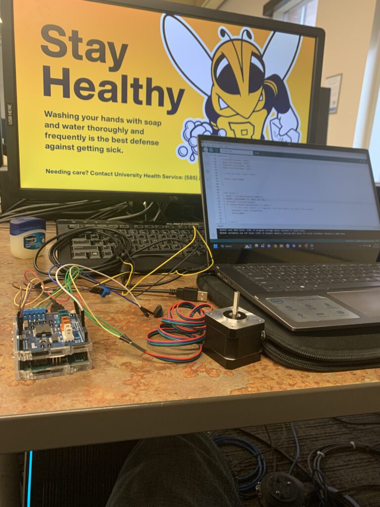
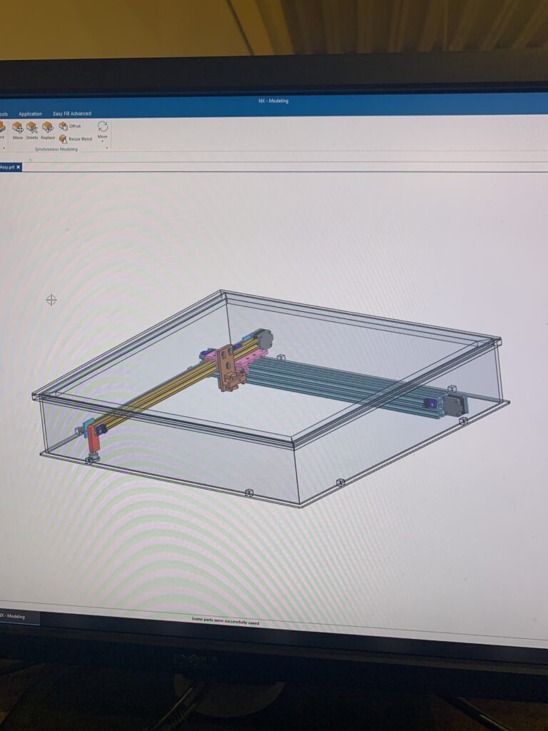
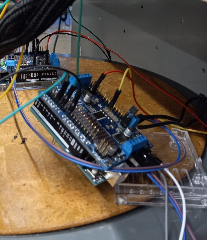
Electronics
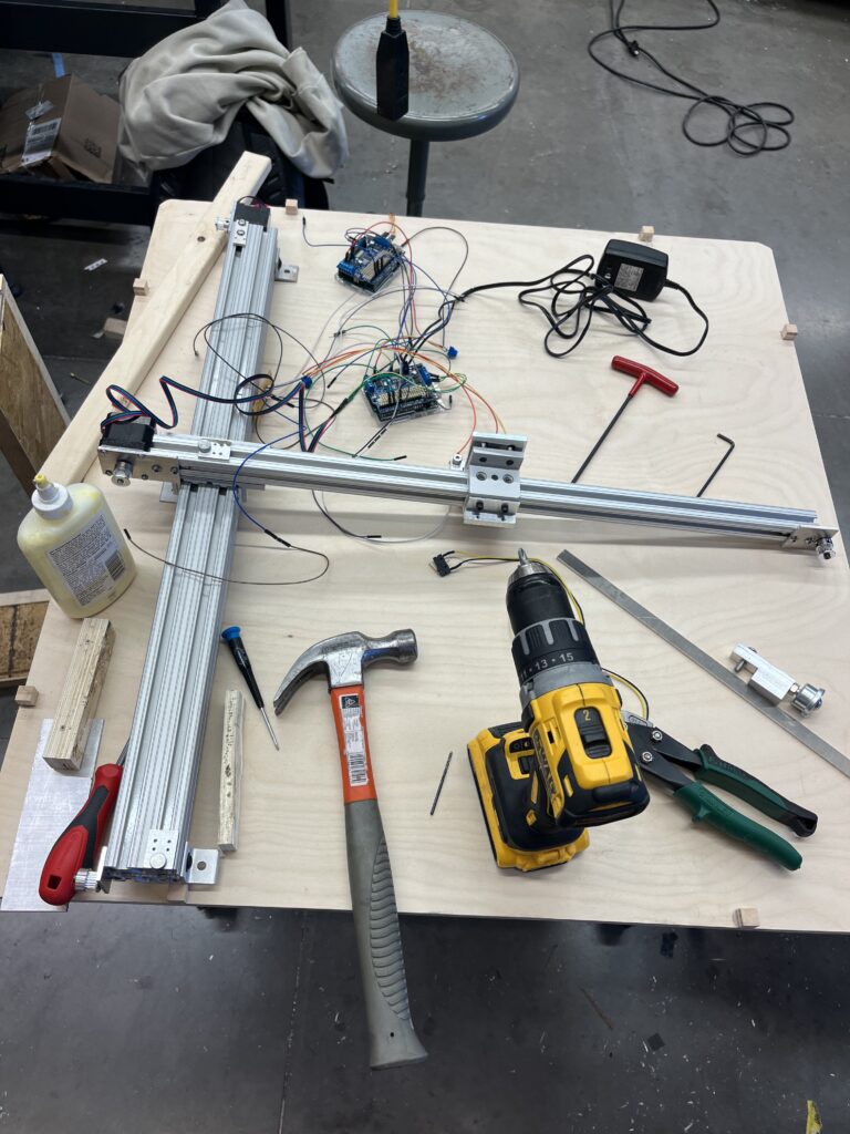
Since the translation stage needs to be motorized, electronics and coding were a huge part of the project. Several concepts were considered for the translation stage (see gallery), but we ultimately settled on the two axis arm concept for its codability and straightforward motion. To achieve this concept we looked to T-slotted frames from 80/20, a great product for linear motion. One of these T-slotted frames is used in either direction, accounting for the x and y directions, and be connected to linear bearings that could slide through the rail. At the end of each rail is a stepper motor connected to a belt to move their respective bearings. Each direction can move independently of the other allowing for both straight and curved lines. Maya took control of the CAD assembly and designed brackets and mounts to connect the electronic components to the rails. Farhan wrote the code and managed the circuitry.
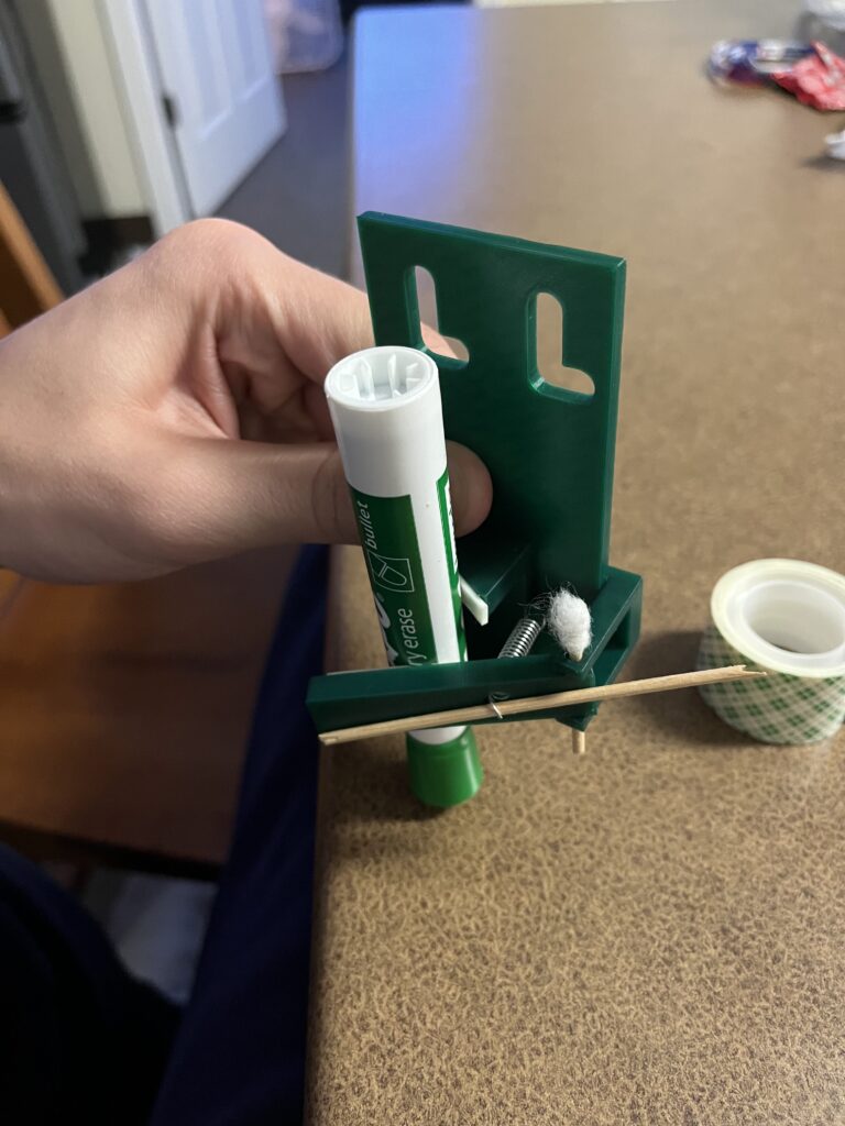
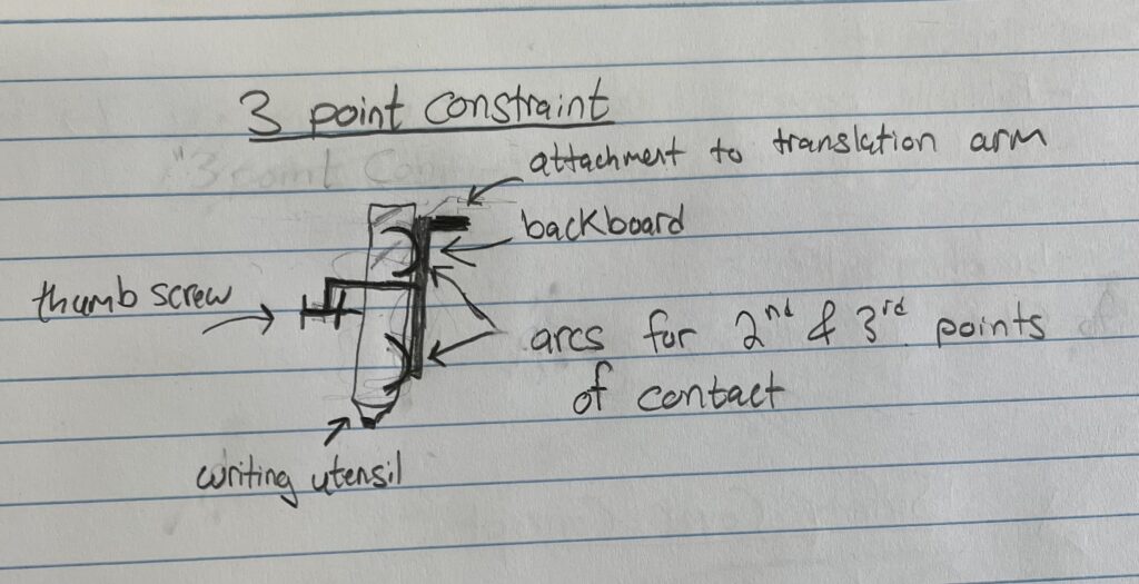
Hardware
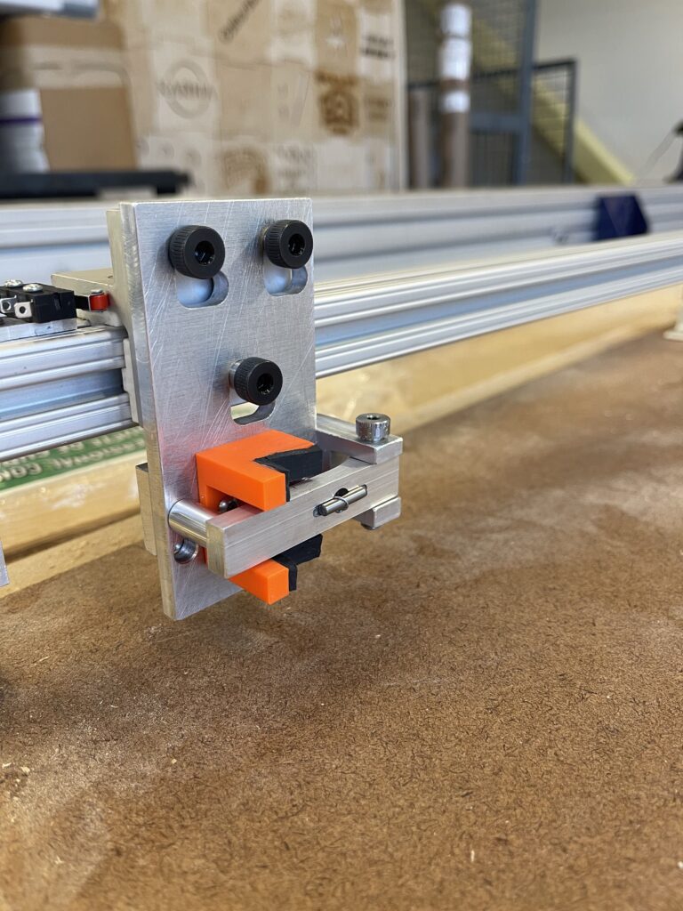
The hardware was split into four major components: the Pen Holder, Safety Cover, Base, and Paper Constraint. The pen holder’s purpose is to constrain the writing utensil to the linear bearing while it moves along the paper. There were many ways to solve this problem, but we settled on a rotating spring-loaded arm to pin the pen to the backboard.
The purpose of the base is to hold all of the components of the assembly. It also needs to support the assembly when picked up and moved from place to place. The chosen design is a rectangular piece of plywood, with small “stoppers” around the edge to prevent sliding of the cover. The safety cover must cover the whole assembly to prevent injury to users of the machine. It must also be see through so users can watch the mechanism working. The chosen design was a box, made with 3 wooden sides for stability, and the front panel clear for visibility. The lid of the box is a piece of polycarbonate that can slide in and out of grooves, so it can be removed so the paper can be changed.

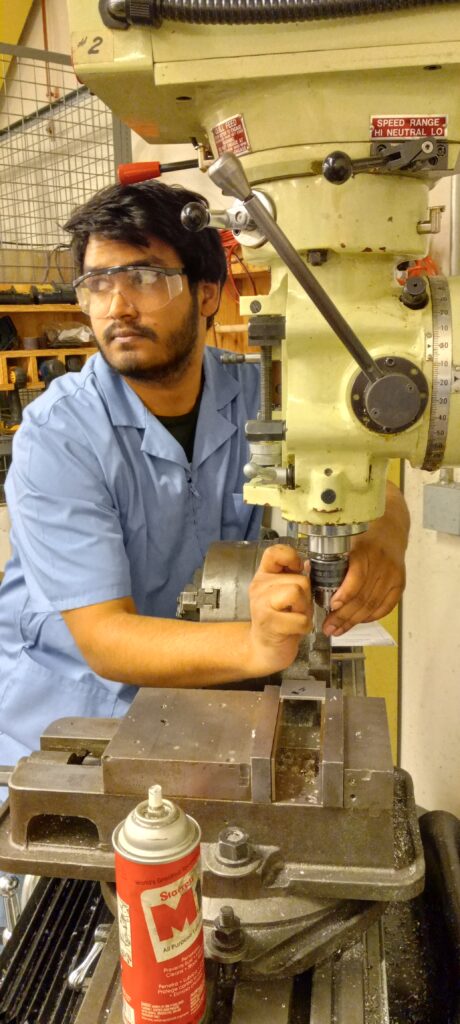
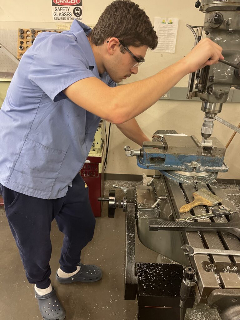
Manufacturing & Assembly
Most of the separate parts in device had to designed and manufactured by hand. This includes the linear slide brackets, the mounts for motors, pulleys, limit switches, and practically the whole pen holder assembly. The only parts that were not manufactured at the University of Rochester were the 8020 rails, carts, and pulley rollers.
Conclusion
The project challenged the team in all aspects of Mechanical Engineering and taught them the responsibilities of being an engineer. Working with Mary Cariola was a pleasure and the skills that they gained through making this device were priceless.
Final Design Report
Final Design Presentation
Acknowledgments
Seth Werlin and the entire Mary Cariola team
Christopher Muir
Chris Pratt
Jim Alkins
Bill Mildenberger
Ed Herger
Doug Kelley
Alex Prideaux
Lyrica Yanaway
Peter Miklavcic