
Team
- Alexandria (Alex) Hajec, University of Rochester
- Mert Gurcan, University of Rochester
- Ziding (Flash) Meng, University of Rochester
Customers

- Igor Faleichik, Nighthawk Solutions
- Makan Camara, Nighthawk Solutions
Advisors
- Ahmet Gurcan, University of Rochester
- Mike Pomerantz, University of Rochester
Additional Assistance
- Ed Herger, University of Rochester, Mechanical Supervisor
Abstract
The purpose of this project was to redesign the telescope from last year’s senior design project in a way that was both more compact and less costly. Our first goal was to implement the use of a smaller (4” diameter) primary mirror for the optical design. Our second goal was to create a mechanical design with x and y axis controls and locks, that could be easily taken apart and placed into a case for ease of mobility. We produced design documents and a final prototype, which we also tested with a live audience. Our product goal was to resolve the Red Spot on Jupiter.
Optical Design
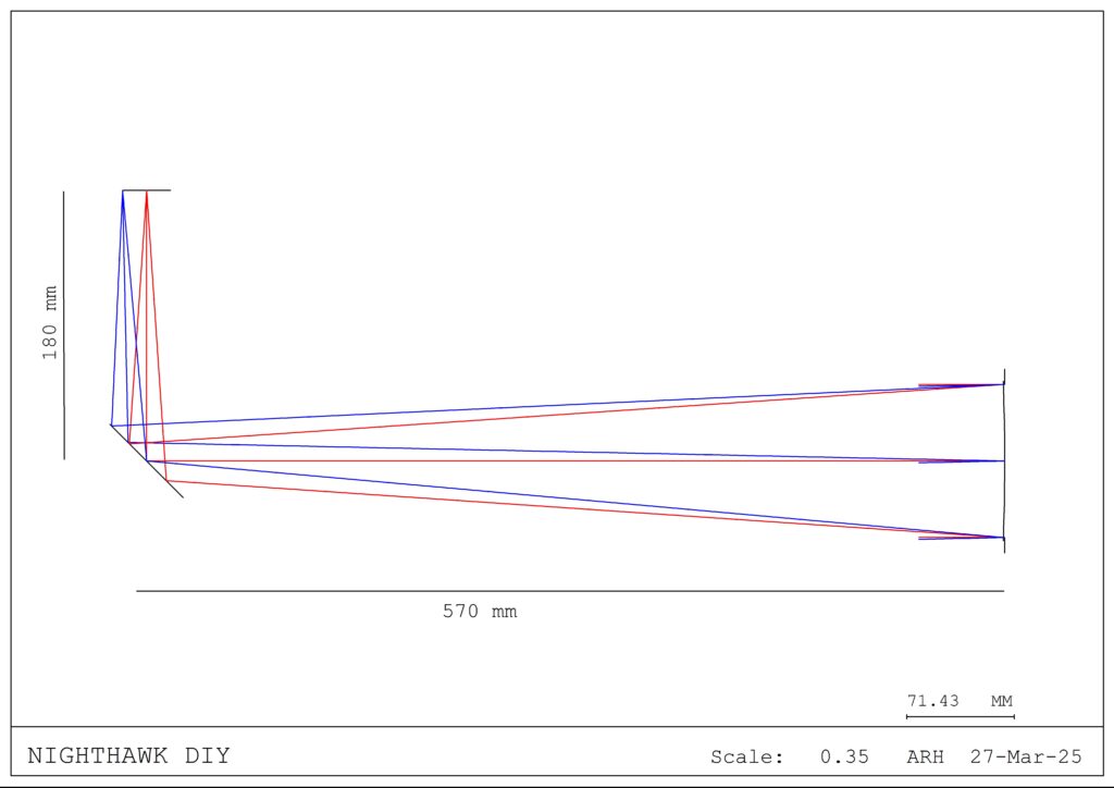
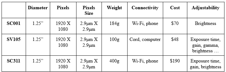
This telescope follows a classic Newtonian design, but there is no eyepiece. We have focused our images onto a high definition CMOS sensor that displays the live view on the user’s device, where images and videos can instantly be saved and shared. We are operating with three types of sensors:
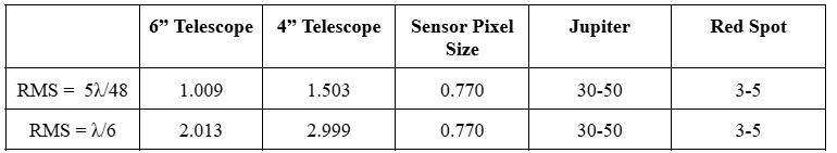
We explored a variety of options with primary mirror sizing and material, and we settled on decreasing the diameter from 6″ to 4″ while keeping the original substrate with Al coating for the sake of the resolution.
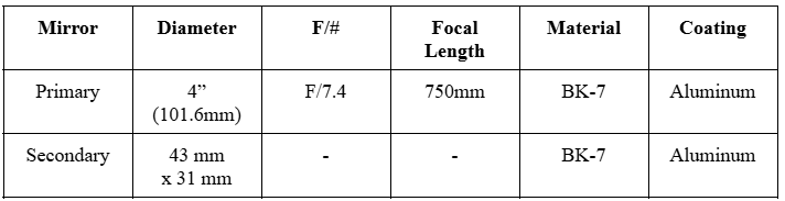
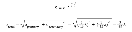
Our resolution was calculated via the Strehl Ratio (S) and the RMS (Ω), in order to take the surface figure of both mirrors into consideration.
Mechanical Design
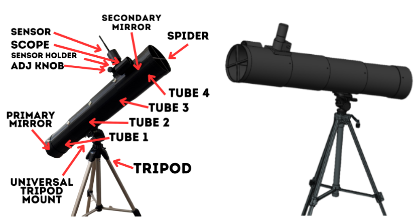
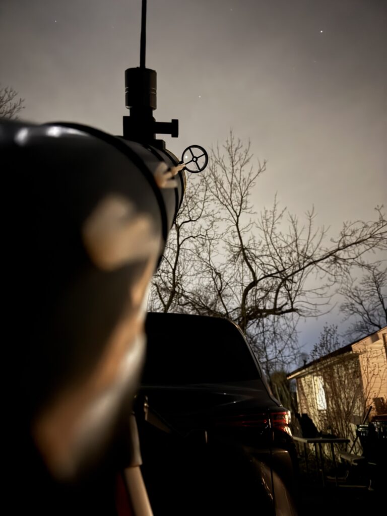
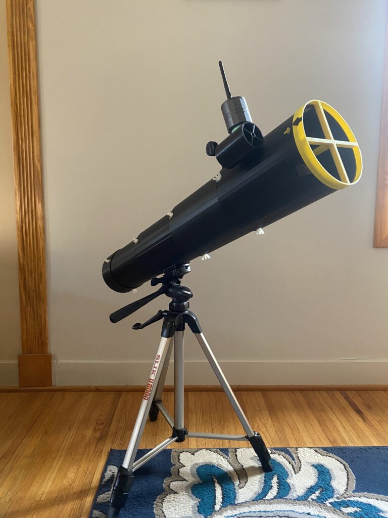
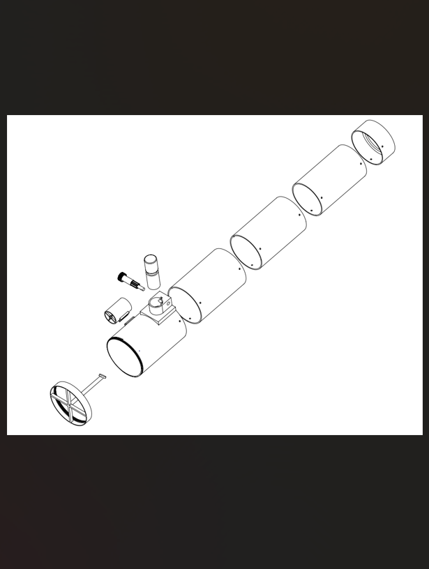
Our tubing mechanism is completely PLA 3D printed, with plastic screws connecting the individual sections of tubing together. We have included a universal tripod mounting mechanism, so the tripod itself is not included in our final design. The primary mirror is UV adhered to the base of the tubing, which is approximately 3′ in length. We have a spider threaded to the front of the tubing, which places the secondary mirror at 45° from the axis of the primary mirror, sending the light directly into the sensor module. This module is user-adjusted to best focus with a fine-focus gear system. It is worth noting that because our telescope does not include an eyepiece, there is only one point of true focus, which can be found by adjusting our gearbox. Also included with the telescope is a spotting scope, which conveniently slides onto the front-most tube section for ease of guiding.
Testing
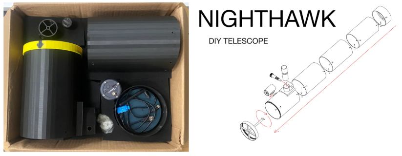
We are creating a commercializable product which comes with a professionally designed instructional booklet and foam packaging. Our goal was to be child friendly, which is shown through our booklets reliance on images rather than written word, and general simple and accessible design of the telescope itself.
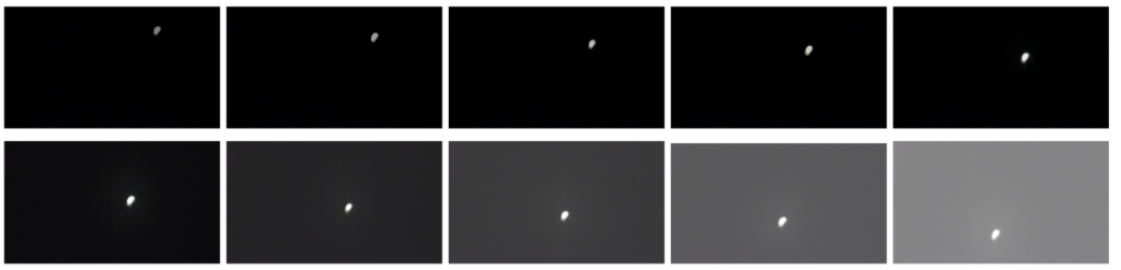
Brightness, shown increasing above, allows the user to only electronically brighten or darken the whole image. Much more effective is the use of exposure time, gain, and gamma adjustments. Exposure time impacts how much light is captured in the image, but can induce blur. Gain, shown increasing below, is like brightness but can amplify noise in an image. Gamma controls contrast in an image, making brighter points brighter and darker points darker.

The biggest hurdle we faced during this was the selection of our sensor, given our general cost constraints and high performance goals. Our original sensor was a wi-fi connectable wireless device that would display the live view on the user’s cellphone. The only variation the user could make on this sensor was the brightness. As a simple system, the lack of customizable control generally makes the system easier to use, but the drawback is that we are unable to control some of the inherent color or shutter controls, resulting in blurry or overexposed images. Our next sensor was a corded version that would display the view on a computer, while the user is able to adjust shutter speed among other settings. Our final sensor was another Wi-Fi compatible sensor, but it had similar settings to the corded version.
Results
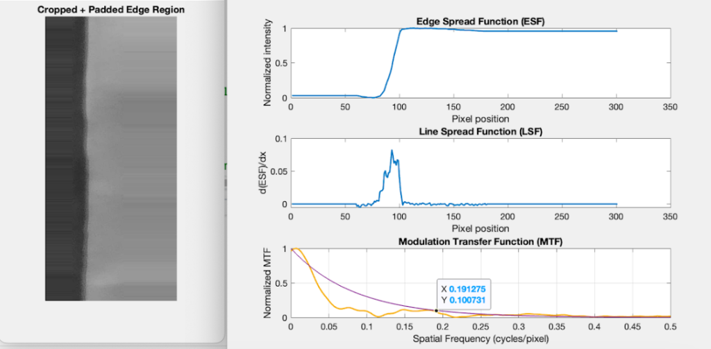
We decided to prove our resolution data by analyzing real images from our telescope, including cropping pictures of a contrast chart to get slant-edged data for Fourier analysis. The Fourier transform of the Line Spread Function of the image gives us the Modulation Transfer Function or MTF of the system, a way of revealing the performance of our system by describing how many pixels we will need to resolve an image. Based on this graph and image, we will need approximately 5 pixels to resolve details in our image. At 0.770 arcsec per pixel, we can only resolve things that are 4.03 arcsec in angular size or larger. We repeated this same process for the other two sensors.
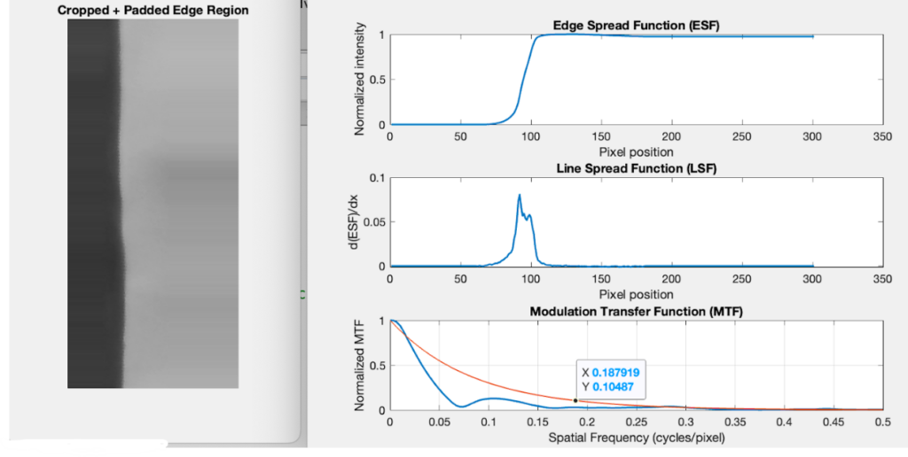
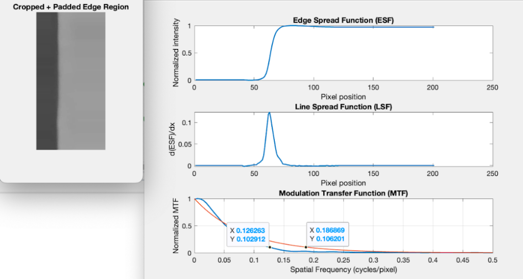
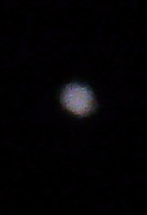
All three sensors should theoretically be able to resolve Jupiter’s Red Spot, which is approximately 3-5 arcsec in diameter. We can see that the first sensor is resolving better than the auto settings on either of the other two sensors, but the MTF smoothness of the final sensor denotes it as the most consistently preforming sensor, and therefore would give the best pictures throughout a number of trials. It is interesting to note, as well, that the images of Jupiter of the three sensors are wildly different.
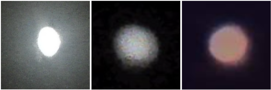
From left to right, we have SC001, SV105, and SC311. These are the best images of Jupiter we were able to obtain from each of the sensors, with no post processing. Through visual inspection, it would appear that the best image comes from the corded (SV105) sensor, followed by the advanced Wi-Fi sensor (SC311), and with the original Wi-Fi sensor (SC001) following behind that. It is worth noting that these images were captured using the user directed settings on the cameras where that was allowed, providing for the best possible aesthetic. The internal processing of each of the sensors is unique, as shown by the color contrast within each image, despite being pictures of all the same object. All in all, the three sensors all perform quite differently, and it is really up to the user which is more applicable for their purpose, with special attention to cost, complication of use, and aesthetic result.
References
[1] SVBONY. SC001 Wifi Spotting Scope Camera. https://www.svbony.com/sc001-wifi-spotting-scope-camera/?srsltid=AfmBOoob0N3UhyDIKlim08PQPsXp_HiiT99BRIcU3FeXqeA265RFM4ao
[2] SVBONY. SV105 Planetary Camera. https://www.svbony.com/sv105-planetary-camera/?srsltid=AfmBOopS_-NdjbP-8h432YJJjW_O-LbSiye8pjt5SZp3eeGqvgpglXSk#F9159B
[3] SVBONY. SC311 Wifi Astronomy Camera. https://www.svbony.com/sc311-wifi-astronomy-camera/?srsltid=AfmBOoo1DCIKl4LgIpZaGRZGy9ds0zL-x2tkfEfmzF_27R3Fjqgwlhcz#F9384A-W9142A