Introduction
This project aims to measure small displacement with low cost but high accuracy. With only a magnified usb camera and a PC, the software can measure the displacement in micrometers.
Set Up
An USB magnified camera, a PC, and a linear stage are used.

Camera
The USB magnified camera are used to capture videos for measurement. Videos will be processed by python which can work for both windows and IOS systems. In order to reach high precision measurement, we ordered digital microscope instead of normal one, so that it can capture more details and smaller range of sight. Also, digital microscopes are about only $30 ~ $50, so it’s really cheap and highly affordable for the high accuracy measurement.
Also, as shown in the picture, the camera is placed in several boxes in order to make the camera parallel to the moving of the linear stage. This parallel placement can reduce angular distortions caused by a tilted camera, and therefore reduce calculated error in the end.
Linear Stage
The linear stage is for compare and contrast. With the precision of 0.01 mm, the linear stage can move precisely and its movement will be counted as the real movement values. The movement of the linear stage will be tracked and measured by the software. All the precision rates are calculated through the difference between real values and the estimated values.
For the convenience of test, a white paper is placed above the linear stage and will be moved together. This step is to keep the background of frames clean such that the software can track a distinct dot on it. As long as there are no other obvious lines or objects besides, the shape and size of dots will be perfectly recognized.
User Interface
The software is developed through Python. Here is an example:
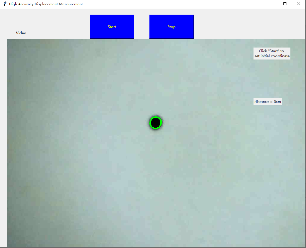
The “start” and “stop” buttons are used to start and stop recording. Whenever the “start” is clicked, the camera will tract the point shown in the frames captured, and record its coordinate. Whenever the “stop” is clicked, the camera will stop tracking the point, and record its coordinate after move. The change of coordinate will be converted to centimeters in the real world.
Tic Control for the Linear Stage
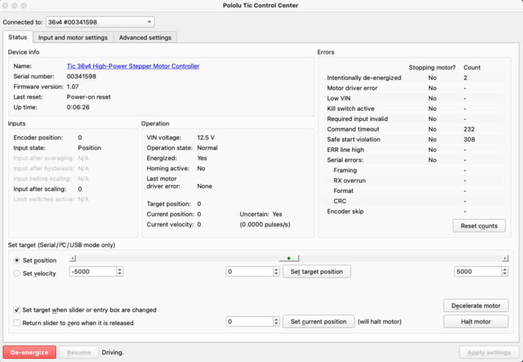
In order to control the linear stage, the Pololu Tic Control Center is used. This software is provided by Pololu. The linear stage has 25000 steps and, for its 250 mm length, each step indicate 0.01 mm.
The video below shows how these two software worked.
How to Use
To get the correct result, you need to:
- Connect the USB camera to your PC.
- Run the software.
- Check the camera such that it aims at target area.
- Click “start” before moving, and click “stop” after moving.
- Record the distance shown.
Test Result
Table 1: Using 0.05in/0.0127cm circle as target (diameter)
| Start Coordinates | End Coordinates | Calculated Results (cm) | Linear Stage Actual Movements(cm) | Percent Error (error/true) |
| (499.8266, 359.6423) | (534.7440, 362.1052) | 0.1056 | 0.1 | 0.56% |
| (499.6796, 359.6158) | (569.8756, 364.6261) | 0.2115 | 0.2 | 1.15% |
| (503.7133, 383.5414) | (608.7401, 390.4491) | 0.3137 | 0.3 | 1.37% |
| (503.7660,383.6518) | (643.8434, 392.8194) | 0.4167 | 0.4 | 1.67% |
| (512.1140, 384.9914) | (679.2739, 395.6052) | 0.4962 | 0.5 | 0.38% |
| (504.1268, 384.1192) | (855.5036, 407.0886) | 1.0495 | 1 | 4.95% |
| (855.5387 407.1017) | (819.7858, 404.7701) | 0.1065 | 0.1 | 0.65% |
| (855.5293, 407.1149) | (784.7859, 402.3358) | 0.2113 | 0.2 | 1.13% |
| (855.6852, 407.1917) | (749.5521, 400.1729) | 0.3152 | 0.3 | 1.52% |
| (855.6087, 407.1420) | (714.5061, 398.0838) | 0.4187 | 0.4 | 1.87% |
| (855.1307, 406.9076) | (679.2630, 395.7556) | 0.5248 | 0.5 | 2.48% |
| (855.5036, 407.0886) | (504.1903, 384.1435) | 1.053 | 1 | 5.30% |
Table 2: Using 0.10in/0.0254cm circle as target (diameter)
| Start Coordinates | End Coordinates | Calculated Results (cm) | Linear Stage Actual Movements(cm) | Percent Error (error/true) |
| (505.7673, 367.5138) | (539.6431, 371.7917) | 0.1072 | 0.1 | 0.72% |
| (505.9802, 367.5259) | (573.8461, 375.4604) | 0.214 | 0.2 | 1.40% |
| (505.6588, 367.3046) | (607.7272, 378.2233) | 0.321 | 0.3 | 2.10% |
| (505.5729, 366.6946) | (641.5972, 380.9811) | 0.4237 | 0.4 | 2.37% |
| (505.1070, 365.2594) | (675.0761, 383.8219) | 0.5301 | 0.5 | 3.01% |
| (514.8506, 374.9989) | (848.4182, 408.2585) | 1.0752 | 1 | 7.52% |
| (503.5790, 369.2604) | (846.6359, 407.5795) | 0.1089 | 0.1 | 0.89% |
| (848.7564, 407.9363) | (779.7231, 400.4650) | 0.2163 | 0.2 | 1.63% |
| (848.5665, 407.7338) | (745.2947, 396.6931) | 0.3215 | 0.3 | 2.15% |
| (848.5149, 408.0385) | (710.9170, 392.4773) | 0.429 | 0.4 | 2.90% |
| (848.7606, 408.0415) | (676.4934, 388.8532) | 0.5404 | 0.5 | 4.04% |
| (846.7522, 407.2363) | (503.7983, 368.9165) | 1.0845 | 1 | 8.45% |
Table 3: Using 0.15in/0.0381cm circle as target (diameter)
| Start Coordinates | End Coordinates | Calculated Results (cm) | Linear Stage Actual Movements(cm) | Percent Error (error/true) |
| (499.8266, 359.6423) | (534.7440, 362.1052) | 0.1056 | 0.1 | 0.56% |
| (499.6796, 359.6158) | (569.8756, 364.6261) | 0.2115 | 0.2 | 1.15% |
| (503.7133, 383.5414) | (608.7401, 390.4491) | 0.3137 | 0.3 | 1.37% |
| (503.7660,383.6518) | (643.8434, 392.8194) | 0.4167 | 0.4 | 1.67% |
| (512.1140, 384.9914) | (679.2739, 395.6052) | 0.4962 | 0.5 | 0.38% |
| (504.1268, 384.1192) | (855.5036, 407.0886) | 1.0495 | 1 | 4.95% |
| (855.5387 407.1017) | (819.7858, 404.7701) | 0.1065 | 0.1 | 0.65% |
| (855.5293, 407.1149) | (784.7859, 402.3358) | 0.2113 | 0.2 | 1.13% |
| (855.6852, 407.1917) | (749.5521, 400.1729) | 0.3152 | 0.3 | 1.52% |
| (855.6087, 407.1420) | (714.5061, 398.0838) | 0.4187 | 0.4 | 1.87% |
| (855.1307, 406.9076) | (679.2630, 395.7556) | 0.5248 | 0.5 | 2.48% |
| (855.5036, 407.0886) | (504.1903, 384.1435) | 1.053 | 1 | 5.30% |
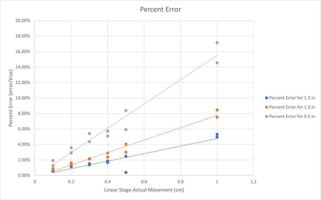
From Table 1, 2, and 3, the plot of percent error shows that both the size of target circles and its movements will cause error. The largest error happens when the real movement is larger than 0.5cm, and the target circle is smaller as 0.5 inch. But even in the extreme cases, the percent error is still within 20%. For most of our testing outcomes, the percent error within 5% is highly optimistic.
Considering for all the results tested, we suggest to use the software for only measuring movements under 0.5 cm, and for objects larger than 0.5 inch.
Prospecting Future
Excluding the outliers, the percent errors of measurements generally falls in between 1% and 3%. With more budgets on the camera and improving the algorithm, the precision of measurement can be reduced even more.