By: Samuel Becker, B.S. Optics 2025
Project Advisors
Dr. Susana Marcos and Dr. James Germann
Abstract
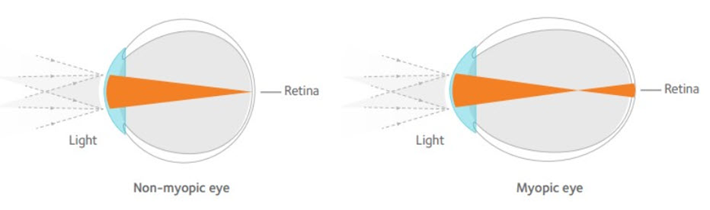
Myopia, the condition of the elongation of the eye, is an increasingly common visual condition that has the potential to cause a great deal of damage to the eye. While the development and effects of myopia have been studied to a great extent, the exact causes and effects of the condition on people have yet to be fully documented due to different reactions in subjects and variance across the visual systems of different people. As technology advances more detailed study into the exact mechanisms of how the eye accommodates is unlocked. This work details the design and assembly of an optical coherence tomography system integrated with a visual simulator that will be able to achieve higher resolution images (<2μm) than previous systems during active accommodation, which will unlock further study into how the choroid and crystalline lens adjust to the myopic eye.
Background
Studies have shown that by 2050, half of the world will be myopic [1], and with that comes increased rates of ocular disease. To design the best treatments, a robust understanding of how the eye accommodates is needed. One such treatment method for presbyopia and myopia often involves multifocal contact lenses, and measurements of the lens thickness will give insight into potential biomarkers for response to this stimulus for these conditions. Additionally, choroidal thickness has been suggested to act as a biomarker for myopia development, and its response to stimulus can be used as an indicator for treatment efficacy [2].
The goal of this project was to design and build an optical coherence tomography system integrated with the visual simulator at the Center for Visual Science. This system will enable very high-resolution thickness measurements of the Choroid and Crystalline lens. These measurements will be taken during active accommodation, which previously has not been done, and will unlock a more detailed picture of how the eye accomodates.
OCT is an interferometric system with a similar setup to a Michelson interferometer. A source is split into a reference and sample arm and then recombined at some detector to measure the interference between the signals. This project uses spectral OCT (sOCT), which uses a spectrometer to detect the interference signal. A first-order diagram of an sOCT system is shown [3].
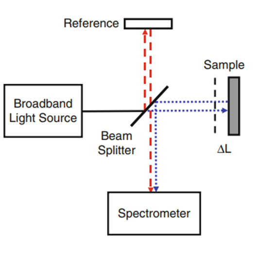
sOCT has the advantage over other OCT methods of using sources like SLDs that can have broader spectral ranges than swept sources, which unlocks very high resolution imaging. Additionally, it is often faster than other OCT methods and has better SNR due to using a spectrometer.
System Design
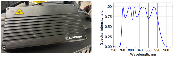
The design of this system was initially started by James Germann, who selected an SLD source with a central wavelength of 850 nm and a bandwidth of 165 nm. This gives a theoretical axial resolution of 1.4 μm in the eye.
Once the source was selected a camera was chosen to pair with it and the spectrometer was designed. The spectrometer was initially designed using the second order of diffraction based on previous OCT systems in Madrid. The grating was narrowed down to two different options and their diffraction angles were calculated and compared shown in the next plot.
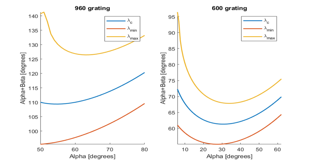
After comparison, the 960 lp/mm grating was chosen due to its higher diffraction angle to keep the system more compact. The incident angle was chosen to be 64 degrees to have the most uniform dispersion of light.
Next, the sample arm was designed in Zemax. The design goals for this were to find the best combination of lenses and method to switch between the Choroid and Crystalline lens focus while minimizing chromatic shift and maximizing the field of view of the system. The principal constraint on the system was the 8 mm pupil to fill the eye, and a 200 mm eye relief constraint needed to integrate with the visual simulator. Diagrams of the final design are shown.
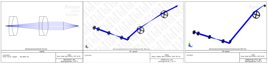
A custom achromatic collimator was made to get an 8 mm pupil and reduce chromatic shift. This light was then imaged through a 1-inch 1x telescope to the galvanometric mirrors and then through another 2-inch 1x telescope to image the light from the galvanometric mirrors to the eye. A movable source and a flip mount on the first two-inch lens were used to adjust the system from imaging on the choroid to the crystalline lens. The final system had good optical quality and a FOV of +/- 5 degrees for the choroid and +/- 1.5 degrees for the crystalline lens.
Because this system is intended to be used on humans, it must comply with the ANSI maximum permissible exposure standards. After calculating for my source characteristics, it was found that the power limit for this system was about 500 μW. Taking the 10% limit of this ensures the system will be operated at an eye-safe limit, which is 50 μW. Using this, I calculated the expected SNR of the system to be 22dB at the 770 nm limit and 21dB at the 930 nm limit.
System Assembly
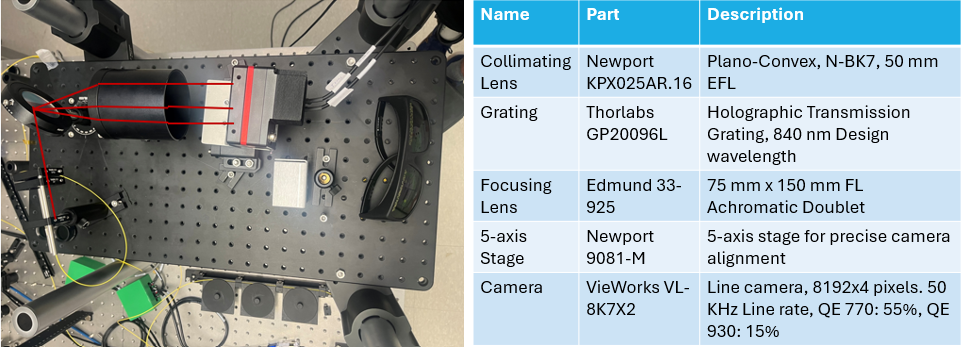
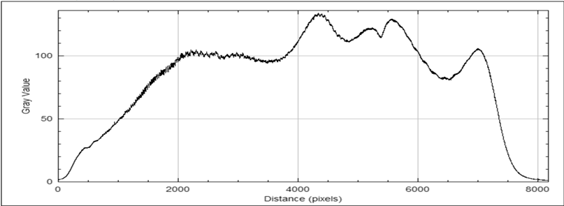
Once all the parts arrived, I began to assemble the system, starting with the spectrometer. The spectrometer was initially built on a separate breadboard according to the theoretical diffraction angles of the design and aligned using the source and neutral density filters until a signal was obtained at 50 μW. The spectrometer was then moved to where to OCT is located and was realigned when hooked up to the rest of the system. An image of the spectrometer is shown along with its important parts. Below is a picture of the spectrum recorded on the spectrometer from my source.
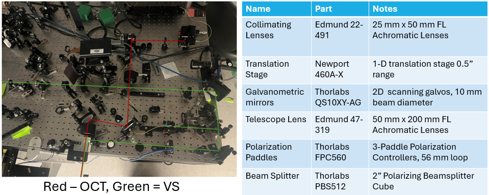
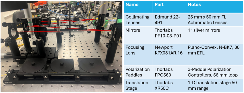
After building the spectrometer, I set up the sample arm according to the initial Zemax design. The source, collimating lenses, galvanometric mirrors, and 2-inch silver mirrors were put in place to define the beam path around the visual simulator. Next, the lenses to image the light from the galvanometric mirrors to the eye were added. The first lens was mounted on a flip mount to adjust focus between the choroid and the crystalline lens. Finally, a beamsplitter was added to the system to combine the OCT and Visual simulator. Upon setting up the beamsplitter, it was found that the beam path of the visual simulator required the beamsplitter to be placed in a location that limited the FOV of the system. Because of this future adjustments to the sample arm and visual simulator will be made to ensure that the full FOV of the OCT system can be used. A picture of the current sample arm set up is shown with the table of parts.
Last, I set up the reference arm. This was built using the same collimators as in the sample arm and was built to have a beam path approximately equal to the sample arm. First, I built the collimation package, source, and lenses. Then I set up all and aligned all the mirrors, and added a focusing lens at the end of the system to simulate the focusing of the eye. After this, I moved the spectrometer to the lab table on top of the reference arm and tested the reference arm signal using the spectrometer. A picture of the reference arm set up is shown along with the table of components.
The source signal for the system is passed through a custom optical isolator to protect it from back reflections, and then is wired via a single mode fiber (Thorlabs P3-780Y-FC-1) to a fiber optic coupler (Thorlabs BXC42) which splits the signal 90% to the reference arm and 10% to the sample arm. The coupler then returns 90% of the signal from the sample arm to the spectrometer and 10% of the signal from the reference arm to the spectrometer. This setup was used when testing the reference arm and will be used when testing the sample arm as well.
Conclusion and Future Work
This project details the design and assembly of the OCT system with a visual simulator. While I was able to finish assembling the reference arm and spectrometer, complications with the sample arm design prevented me from finishing the system until measurements with the current visual simulator set up are finished. Some challenges for building a system of this style were to get good spectral resolution with the broadband source, the spectrometer needs to use a line camera with a large number of pixels, which leads to using very large optics and can be difficult to set up without the proper optomechanics. Additionally, building an OCT with a visual simulator will often require a large eye relief requirement that will heavily restrict FOV and force the OCT system to have a limited focusing range. Future work to finalize the system development of the system includes finishing the sample arm and obtaining verification of interference between the sample and reference arm, spectrometer k-space linearization, and syncing of galvos and camera triggers. Additionally, testing with a Model Eye will most likely involve correcting fan distortion, and verification of the OCT working in conjunction with the Visual Simulator is needed. After the system is built, future studies to better understand myopia and develop the best treatments will be started.
Acknologments
I would like to thank both Dr. Susana Marcos and Dr. James Germann for advising me on this project. Special thanks to David Fernandez as well for his help with Zemax. Additionally, I would like to thank the entire Marcos Lab for being so welcoming and supportive. Lastly, I would like to thank Professor Knox for his guidance during my senior thesis.
References
[1] Holden, B. A. Global Prevalence of Myopia and High Myopia and Temporal Trends from 2000 through 2050. Ophthalmology vol. 123,5 (2016). [2] Wisely, C. The chick eye in vision research: An excellent model for the study of ocular disease. Prog Retin Eye Res. (Nov. 2017). [3] Fujimoto, J. G. & Drexler, W. in Optical Coherence Tomography: Technology and Applications (eds Drexler, W. & Fujimoto, J. G.) 3–64 (Springer International Publishing, Cham, 2015). isbn: 978-3-319-06419-2