Screw Insertion Trajectory Kit for Open Reduction Internal Fixation (ORIF) Orthopedic Surgery
Don’t screw it up!
Meet the Team

Connect with us on LinkedIn!

Abstract
During open reduction internal fixation (ORIF) surgery, orthopedic surgeons insert metal screws by way of implanting bone plates. However, concern arises when the screw trajectory does not remain co-linear with the pre-drilled pathway and results in insufficient purchase in the far cortex of the bone. Thus, our technology involves a trajectory tracking device that gives surgeons real-time feedback on the angle and position of the screw trajectory.
Background
Bone fractures, with a global incidence rate of 2,296.2 cases per 100,000 population in 2019 [1], can occur anywhere on the body and could be due to traumatic injuries or diseases, such as osteoporosis [2]. Lower leg fractures of the patella, tibia/fibula, and ankle were the most common with an incidence rate of 419.9 cases per 100.000 population [1]. Fractures can lead to economic burdens, disability, impaired quality of life, health loss, and high health-care costs, especially in the United States (US) [1]. According to a study conducted by J. N. Farr, et al., about 80% of fractures are due to traumatic injuries [3]. Another study reported about 8% of the 12-15 million traumatic fractures in the US resulted in inpatient hospitalization between 1998 – 2010 [4].
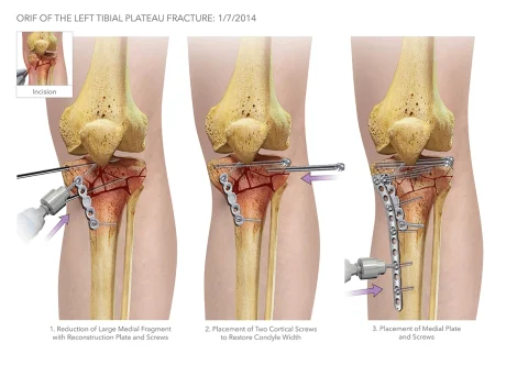
Traumatic fractures are the most common cause for open reduction internal fixation (ORIF) surgery, which is an emergency orthopedic procedure performed when a bone fracture is severe enough to need hardware (plates, screws, rods, etc.) to realign and hold the fragments together [5]. The following are the types of hardware used during ORIFs [5]:
- Screws: Can be used alone or with other types of hardware, such as plates and intramedullary rods.
- Plates: Acts as internal splints to hold the bone in place; screws are typically used to secure the plate to the bone
- Intramedullary Rods: Inserted through the center of bones; typically used for certain types of long bone fractures; screws are used to hold the rods in place
- Wires or pins: Used to pin small bone fragments in place; can be used with other hardware or alone
Most of the hardware used is left in the body once the fracture heals. They are only removed if there is an infection or need for revision surgery.
The Problem
During ORIF surgeries, orthopedic surgeons tend to use a “freehand method” to place the screws along the plates. For this method, surgeons will use a scalpel or forceps while x-ray imaging with a C-arm to determine and mark the angle trajectory for screw insertion. The surgeons will then remove the marking guide when switching to the drill to create a pilot hole in the bone for the self-threading screws to be placed into. During the screw insertion process, x-ray images are taken on a C-arm for each adjustment of the marking guide until its angle matches the trajectory of the pilot hole. As the surgeon switches to the drill to insert the screw, the marking guide is removed. Concern arises due to the surgeons not being able to repeat the specific angle their marking guide was placed and how accurate they can be when inserting the screws in the pilot hole. When the screws are not inserted at the proper trajectory, two different adverse events may occur:
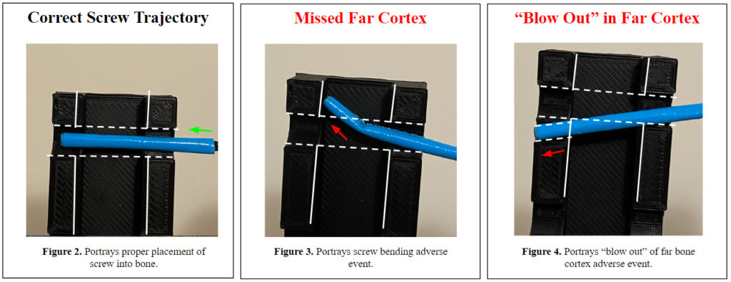
- The screw tip bends at the far cortex of the bone (Fig. 3), which increases the risk of fragmenting and diminishing the ‘purchase’ in the bone.
- The screw does not stay collinear to the trajectory of the pilot hole; thus, creating a new path and ‘blowing-out’ the far cortex of the bone (Fig. 4), which further fractures the bone and causes insufficient purchase.
The current solutions to these two complications are to insert additional screws to maintain proper fixation or remove the improperly placed screw for reinsertion, with the former being the more common method. In addition to the patient-related adverse events, the “freehand method” exposes the surgeon and OR staff to an extensive amount of fluoroscopic radiation. Therefore, our solution, the ScrewIT Kit, aims to mitigate the risk of the two adverse complications and the need for re-drilling or the insertion of additional screws as well as reduce fluoroscopic radiation exposure.
Biodesign Statement
To reduce unfavorable fixation outcomes suffered by patients during ORIF surgeries due to incorrect screw placement
Design History
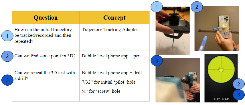
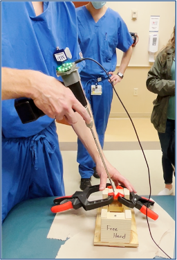
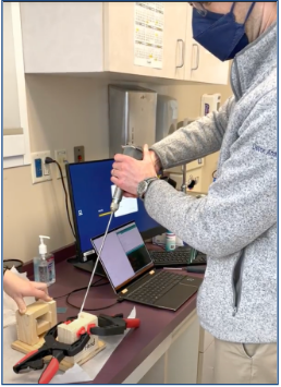
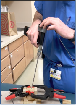
The initial design concepts that were considered and tested in the preliminary prototype phases aimed to answer the following questions. The first iteration involved a trajectory tracking adapter a strictly mechanical design modeled by a car phone mount to test the idea of “locking” a set angle (1). However, the limiting factor of this prototype was the inability to control the degrees of freedom. The second concept involved a bubble-level mobile phone app and a pen (representing the drill bit + screw) and introduced the idea of using a more software-based approach (2). This was then translated to a standard power drill (3) which produced similar outcomes and the promising results became the foundation for the final solution.
Our Solution: The ScrewIT Kit
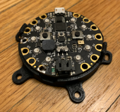
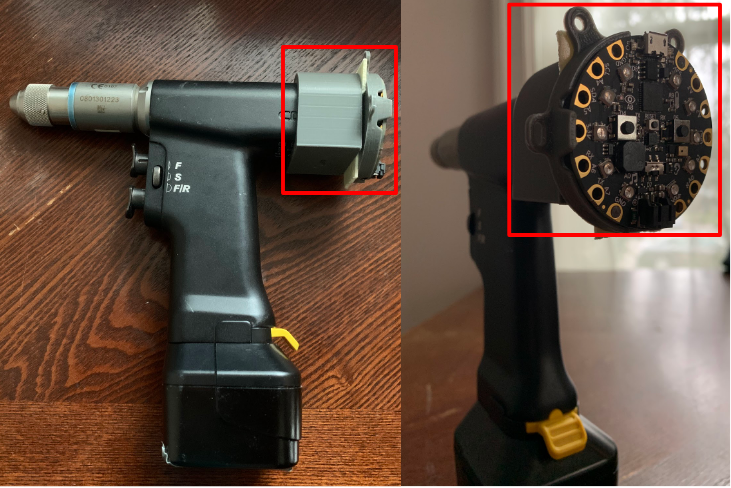
The ScrewIT Kit is an attachable 3D accelerometer assistive tracking system that provides real-time feedback for the screw trajectory insertion process unlike the current free-hand method or existing technologies that are not specifically designed for ORIF screw placement. Our device is comprised of a microcontroller with two push-buttons, a buzzer (audio) box, and a set of 10 LEDs arranged in a circular configuration (Fig. 5). It is mounted on an attachable piece that could be adjusted to fit the proximal end of a pre-existing bone drill (Fig. 6) and powered by a 6 V battery.
The device utilizes Arduino software to record and measure the real-time coordinates or orientation of the drill as the surgeon is moving it. The program takes into account two reference points (calibration point and target point) to calculate the desired angle trajectory. All reference coordinates are saved locally by pushing associated push-buttons, in which audio feedback will be played to indicate that data is saved.
The target trajectory is used by the program as a comparison value to guide the user’s real-time position to the correct orientation. When using the device, some LEDs on the device will light up red to indicate the direction to move away from in order to hit the target angle. In other words, the unlit LEDs indicate the direction to move towards. Once the target angle is reached, all the LEDs will light up green.
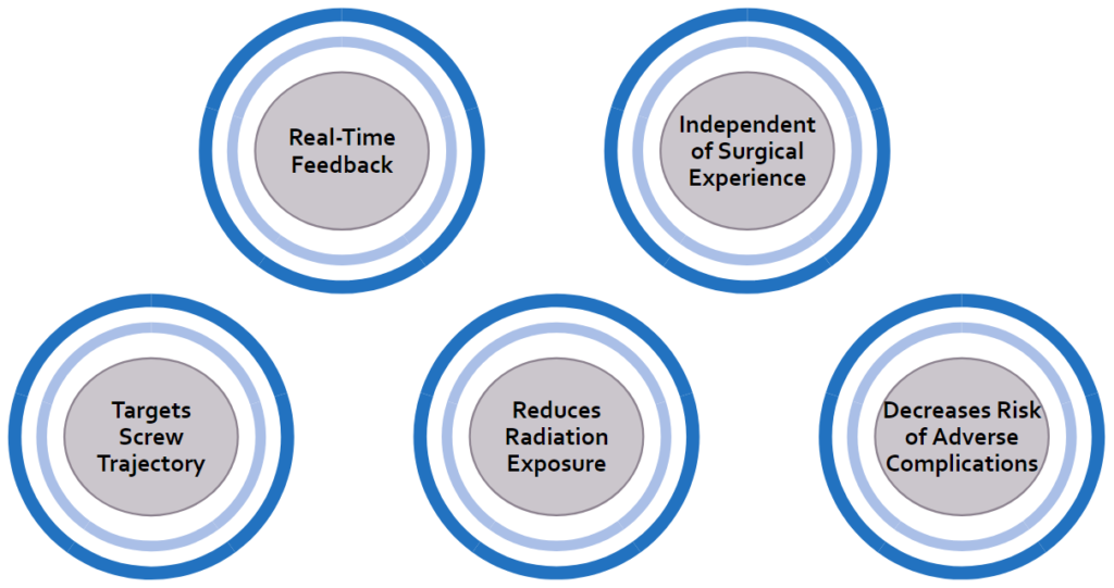
Key Benefits of Our Solution
How to Use The ScrewIT Kit
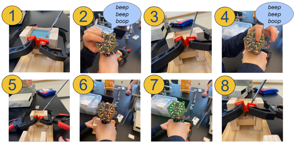
Here is an animation of how the device would be used:
1. Insert drill into calibration point
2. Press and hold the left button (above the buzzer box) until a chime is played to save calibration data
3. Drill a pilot hole at the desired angle
4. Before removing the drill from the pilot hole, press and hold the right button until a chime is played to save the target data
5. Remove the drill from the pilot hole and start screw insertion
6. If the drill is at the incorrect trajectory, some LEDs will flash red
7. Move in the direction of the unlit LEDs until all LEDs flash green
8. When all LEDs are green, proceed with the screw insertion
Existing Methods vs Our Solution
Heuristics & Human Factors
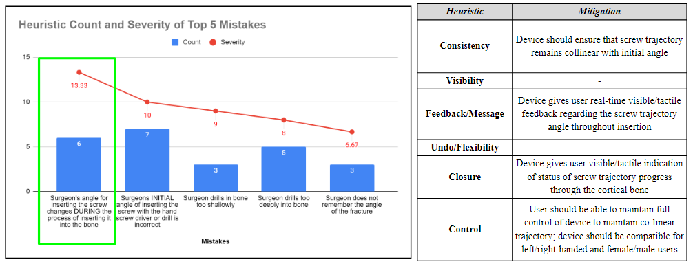
After completing a Heuristic and Human factors analysis, the top 5 potential human factor errors were determined using a rating scale that considered the severity and probability of occurrence of each event. Heuristic categories were assigned to each of these errors, and respective mitigation plans were developed to address these concerns and mitigate the human factor errors.
Testing & Data
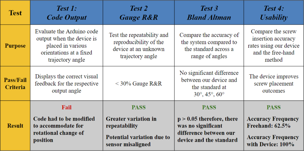
Test 1: What does the code output?
Goal: To evaluate the Arduino code output when the device is placed in various orientations at a fixed angle.
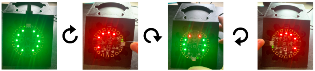
Method: A 3D printed holder was used to place the device at a fixed angle of 45° and rotate it 90° in a clockwise fashion. The LED indicators were noted in each position as shown in Fig. 9.
Pass/Fail Criteria: Displays the correct visual feedback for the respective output angle.
Results: When the device was placed at the original (0°), the Arduino code outputted an angle of 45° ± 2°, and all the LEDs lit up green, which indicated that the target trajectory was reached. However, when rotated to the 90°, 180°, and 270° positions, the angle outputs were the same, but some of the LEDs lit red, which indicated that the trajectory angle was not reached and there needs to be an orientation adjustment. These results demonstrated that the visual feedback component of the code failed to recognize that the angle remained the same regardless of the changing coordinates points.
Therefore, the code had to be modified to accommodate for rotational change of position (i.e., the surgeon rotating their wrist) and display the appropriate visual feedback based on the vectors of the saved ‘target angle’ rather than solely the coordinate locations in the x- and y-axis.
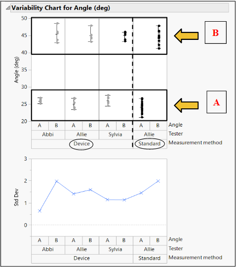
Test 2: Does our device allow for repeatability and reproducibility?
Statistical Method: Gauge R&R
Goal: To determine if our device can provide consistent results between different users and across multiple trials.
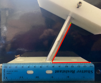
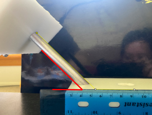
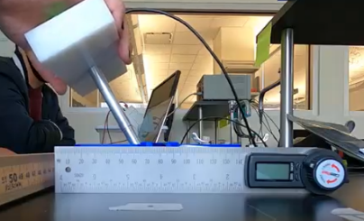
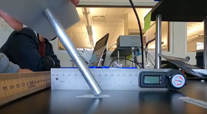
Method: Three different testers used our device to measure two different, random angles (A (Fig. 12) and B (Fig. 13)) in a series of three trials. These angles were also measured using ImageJ software (standard).
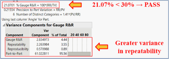
Pass/Fail Criteria: < 30% Gauge R&R
Results: The % Gauge R&R value was 21.07% which is less than the accepted value of 30%. There was greater variation in the repeatability, but the low reproducibility showed that our product can be used to bridge the gap between surgeons of various experiences.
Test 3: Is our device accurate over a range of angles?
Statistical Method: Bland Altman Analysis
Goal: To determine if our device is accurate over a range of angles.
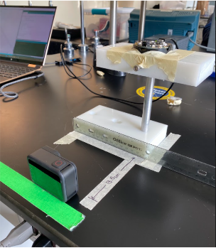
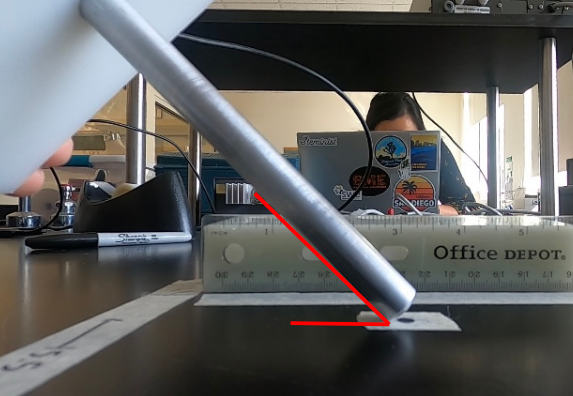
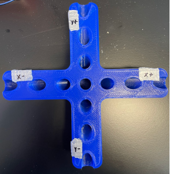
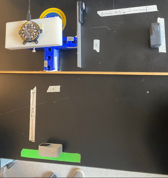
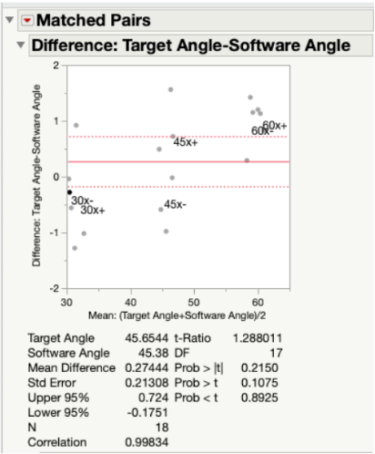
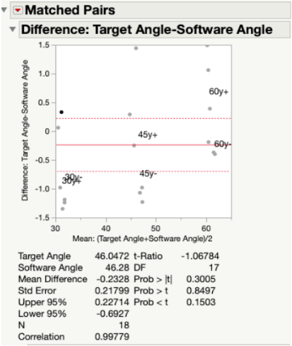
Method: As seen in Fig. 16, we used a t-shaped testing jig that allowed us to test multiple angles in different coordinates. Our testing jig contained three different angles, 30°, 45°, and 60° that were tested along the x-axis (x+, x-) and y-axis (y+, y-).
Pass/Fail Criteria: No significant difference between our device and the standard at 30°, 45°, 60°.
Results: Since our p-value was >0.05 for all angles measured along both the x-axis (Fig. 19) and y-axis (Fig. 20) of the testing jig, it was determined that there was no statistical difference between our device (measured angles) and our standard (target angles). Therefore, our device is accurate at testing different angle measurements, even considering the ± 2° of variability that is embedded into the Arduino code. Ultimately, this test demonstrated that our device can be utilized at a large range of angle trajectories to provide the user with precise indications for when to insert the screws into the pre-drilled pathways in the bone.
In Fig. 21, all target and measured angles taken along the x- and y-axis of the testing jig were plotted against each other in a linear regression graph. In this plot, the green dots represent the angles taken along the y-axis and the blue dots represent those taken along the x-axis. At each tested angle, all of the data points are clustered together. The linear fit line that was created between all data points was found to have a slope of 0.955, which indicated a very strong correlation between the target angles and the measured angles. In other words, the measured angles were numerically very close to the target angles.

Test 4: How does our device compare to the free-hand method?
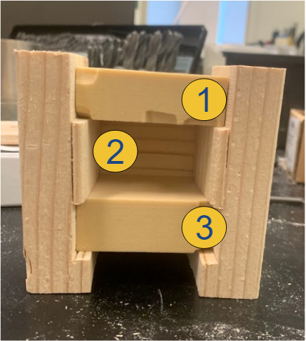
Goal: To compare the screw insertion accuracy rates using our device and the free-hand method in a use case scenario with a pseudo-bone model.
Method: The pseudo-bone model shown in Fig. 22 represents a worst-case scenario of the sagittal view of a bone section with the superior bone block representing the near cortex (1), the open space representing the medullary trabecular bone (2), and the inferior bone block representing the far cortex (3). This open perspective was hidden from the testers’ field of view, so they could not see the drill trajectory while performing the procedure. Each tester was instructed to first, drill a pilot hole and insert a 70 mm long screw using the unassisted free-hand method, then repeat the process using the feedback of the attached device.
Pass/Fail Criteria: The device improves screw placement outcomes.
Results: Of the total 8 test subjects that ranged from no medical training to attending orthopedic surgeon, there was a 100% accuracy screw placement while using the device, compared to a 62.5% accuracy using the free-hand method.
Customer Feedback

Orthopedic Trauma Surgeon at URMC
X-ray is helpful [with free-handing], but you only get one plane of view and…it is very time-consuming
[Incorrect screw insertion trajectory] will “blow out” the far cortex or not get adequate purchase…[the] screw could also bend in the medullary canal
[I rely on] practice/experience, muscle memory and natural ability for spacial awareness
[The] downside of the [Smith & Nephew] SureShot is that it only works with their [intramedullary] nail and is huge

Orthopedic Oncologist at URMC

Orthopedic Hand Surgeon at URMC
This device will reduce the amount of radiation exposure in the OR
Great training tool for residents
Good to get lesser experienced surgeons up to speed faster
Your device could also be very useful for joint replacement surgeries
Orthopedic Joint Reconstruction & Replacement Surgeon at URMC
Market Opportunity
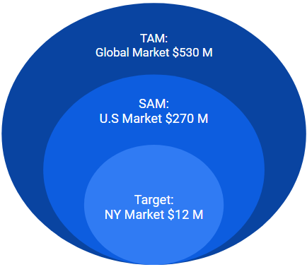
The ScrewIT Kit is part of the Large bone Orthopedic Surgical Power Tools Market:
- Total available market (TAM): Global market = $530 M USD in 2020 [7]
- Part of the total global surgical power tools market = >$1.8 B USD in 2020 with a projected CAGR of 6.5% from 2021 to 2027 [7]
- Served available market (SAM): US market = $270 M USD in 2020
- Accounts for ~50% of the global market [8]
- Target market: New York (NY) state market = $12 M USD in 2020
- Accounts for ~4.5% of US market [8]
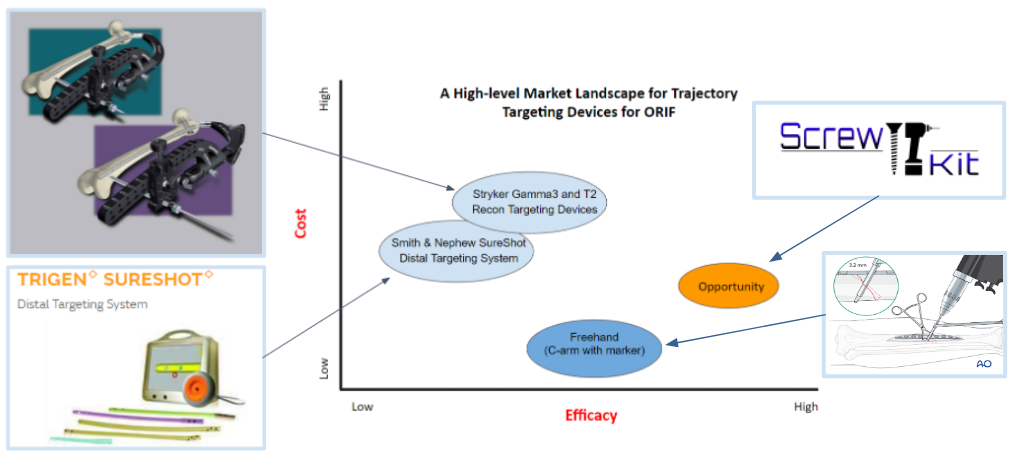
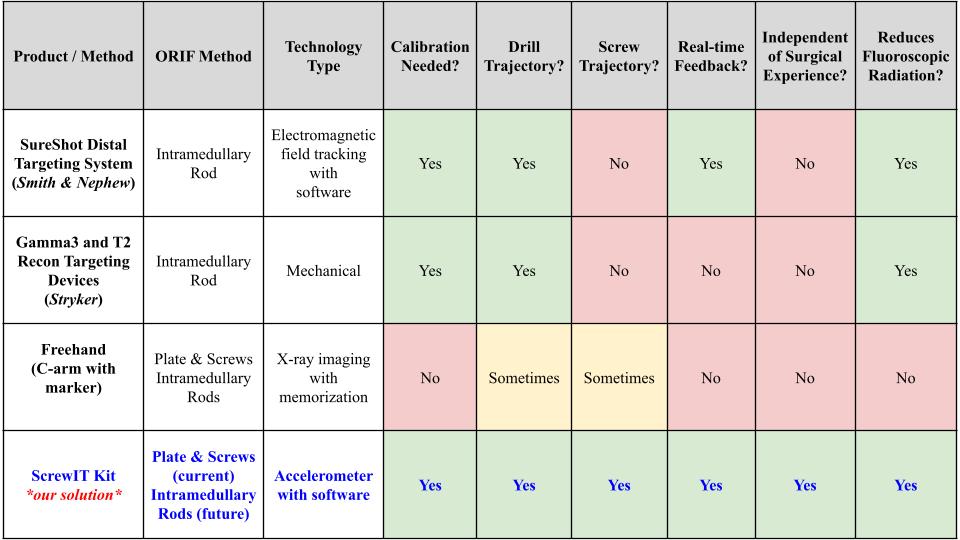
In Fig. 27, the light blue circles indicate current competing technologies, while the dark blue circle indicates a free alternative method utilized by surgeons; the orange circle indicates the opportunity gap in the market. Smith & Nephew SureShot and Stryker Targeting Devices are ranked similarly in terms of efficacy and cost. The Stryker device is only placed a bit higher in both variables because it is used more often than the SureShot device according to our voice of customer (VOC) feedback. The alternative “freehand” method is the lowest cost and has higher efficacy than the current technologies due to surgeons relying more on the C-arm with markers and memory than on using the available products. VOC feedback claims that the current products are “cumbersome and time consuming” to use and don’t work well enough. Therefore, there is a market opportunity gap in the market to create a product that has higher efficacy than the other available methods/devices and lower cost than current commercial products to address the screw trajectory need during ORIFs.
Regulatory Strategy
Class: II
Product classification code: PBF/OLO
FDA Pathway: 510(k) clearance
Predicate devices: Smith & Nephew SureShot Distal Targeting System (K180277) and Stryker Gamma3 and T2 Recon Targeting Devices (K123401)
Intended use: An assistive device for orthopedic surgeons, used to ensure the trajectory path of a screw remains co-linear to a pre-drilled hole.
Indication for use: An assistive device for orthopedic surgeons, used to maintain a co-linear screw trajectory pathway to a pre-drilled hole during insertion through a bone plate for long bone fractures in ORIF surgery.
Our device would still be subject to design controls and good manufacturing practices (GMP) per guidance issued by the FDA. It would also be required to adhere to the following internationally recognized industry standards:
- ISO 13485 Quality Management Systems
- ISO 14971 Application of Risk Management to Medical Devices
- ISO 10993 Biological Evaluation of Medical Devices
- ANSI/AAMI HE75 Human Factors Engineering of Medical Devices
Future Considerations
- Submit provisional patent application
- Add different attachment placements on the drill to offer alternative positions to view visual feedback and not obstruct the surgical field of view
- Optimize code to be more streamlined and in accordance with industry quality standards
- Based on VOC feedback, adapt our device for further applications, such as intramedullary rod ORIFs and knee and hip arthroplasty
Acknowledgments
We would like to thank all of our advisors and mentors who have significantly helped us with the development of the ScrewIT Kit!
Greg Gdowski, PhD. – CMTI Executive Director
Martin Gira – CMTI Senior Research Engineer
Amy Lerner, PhD. – CMTI Academic Director
Mahllet Beyene – CMTI Graduate Program Coordinator
Jonathan J. Stone, M.D. – CMTI Clinical Director, URMC Neurosurgeon, Business Coach
Addisu Mesfin, M.D. – CMTI Global Health Director, URMC Orthopedic Spinal Surgeon
John Boger, Esq. – Patent Lawyer, IP
Joan Adamo, PhD. – Director of Regulatory Support Services
Sandeep P. Soin, M.D. – URMC Orthopedic Trauma Surgeon
Thomas G. Myers, M.D., M.P.T. – URMC Orthopedic Joint Reconstruction & Replacement Surgeon
Bilal Mahmood, M.D. – URMC Orthopedic Hand Surgeon
Susan M. McDowell, M.D. – URMC Orthopedic Oncologist
Scott Brugler – Stryker Medical Device Representative
References
[1] GBD 2019 Fracture Collaborators, “Global, regional, and national burden of bone fractures in 204 countries and territories, 1990-2019: A systematic analysis from the global burden of disease study 2019,” The Lancet. Healthy longevity, Sep-2021. [Online]. Available: https://www.ncbi.nlm.nih.gov/pmc/articles/PMC8547262/.
[2] L. Esposito, “Bone and joint diseases: Types, symptoms … – US news health,” U.S News Health , 19-Jul-2019. [Online]. Available: https://health.usnews.com/conditions/bone-and-joint-disease.
[3] J. N. Farr, L. J. Melton, S. J. Achenbach, E. J. Atkinson, S. Khosla, and S. Amin, “Fracture incidence and characteristics in young adults aged 18 to 49 years: A population-based study,” Journal of bone and mineral research : the official journal of the American Society for Bone and Mineral Research, Dec-2017. [Online]. Available: https://www.ncbi.nlm.nih.gov/pmc/articles/PMC5732068/.
[4] A. N. Pollak and S. I. Watkins-Castillo, “Fracture trends,” BMUS: The Burden of Musculoskeletal Diseases in the United States, 2014. [Online]. Available: https://www.boneandjointburden.org/2014-report/via23/fracture-trends,
[5] D. Brennan, “Orif surgery: When it’s needed and how it’s done,” WebMD, 20-May-2021. [Online]. Available: https://www.webmd.com/a-to-z-guides/what-is-orif-surgery.
[6] ORIF of Left Tibial Plateau Fracture, highimpact.com, Jan. 7, 2014. [Online]. Available: https://res.cloudinary.com/high-impact/image/upload/if_h_gt_w,ar_4:4,c_lpad/c_scale,w_460,f_auto/HI/images/jcogs_img/cache/2de25d468ec6db4e490cb4663b7156c70090cb25_-_abcdef_-_95ddaf8a93b9d7b99c479f3ad629933e43054a18.jpg (image)
[7] ORIF of Left Tibial Plateau Fracture, highimpact.com, Jan. 7, 2014. [Online]. Available: https://res.cloudinary.com/high-impact/image/upload/if_h_gt_w,ar_4:4,c_lpad/c_scale,w_460,f_auto/HI/images/jcogs_img/cache/2de25d468ec6db4e490cb4663b7156c70090cb25_-_abcdef_-_95ddaf8a93b9d7b99c479f3ad629933e43054a18.jpg
[8] “Surgical Power Tools Market | Global Forecast Report 2027”, Global Market Insights Inc., 2022. [Online]. Available: https://www.gminsights.com/industry-analysis/surgical-power-tools-market.