The hybrid endoscope/microscope project is a senior design project that aims to design and build a system that combines the view of an endoscope and microscope, which will allow doctors to switch between the two views within seconds during surgery. This project is conducted with the help of our project customers Dr. Paul Dutcher and Dr. James Manning, surgeons at URMC, and the support of our faculty advisor, Professor Greg Schmidt.
The Team

Lyse Mugeni
Project Coordinator, Customer Liaison

Lauren Scheg
Scribe
lscheg2@u.rochester.edu

Tianshu Xu
Document Handler
txu12@u.rochester.edu
Customers

Dr. Paul Dutcher

Dr. James Manning
Faculty Advisor
Prof. Greg Schmidt
Project Overview
Vision
The hybrid endoscope/microscope project aims to design and build a system that combines the endoscope’s view and the microscope’s view, which will allow doctors to switch between the two views within seconds during ENT surgery. We proposed an image projecting system integrated into the microscope to project the endoscope’s image to the intermediate image of the microscope that can be viewed through the microscope’s eyepiece.
Background
Neurotology is a subspecialty of Otolaryngology-Head and Neck Surgery. Neurotologists surgically treat various disorders that affect hearing and balance within the temporal bone and even within the cranial vault. The small confines of the surgical fields and their narrow points of access necessitate microscopic and endoscopic views and the use of micro-neurotologic instruments. The setup, spatial organization, and sterility of the bulky instruments used to visualize the surgical field presents a challenge for the surgeon and operating room staff. Given the spatial constraints within the operating room and the operative field, instruments would ideally be consolidated to one unit when possible and compact in size.
At present, the endoscope, microscope, and suctioning tube are separate pieces of equipment. During an operation, the ENT surgeon often needs to switch between scopes depending on the field of view necessary. The endoscope provides a large FOV with slight magnification, and the microscope offers a small FOV with high magnification. When switching from microscopic to endoscopic view becomes necessary, changing between equipment is cumbersome and increases OR time. For specific disease processes, inadequate visualization can result in residual disease, often requiring further surgery. An additional problem is presented with the use of the suctioning tube. The surgeon must hold the endoscope in one hand and either an otologic instrument or the suction in the other. The use of the endoscope essentially requires the surgeon to operate with only one hand. Thus, a product that integrates these multiple functions could significantly improve the efficiency of otologic surgery.
Fitness For Use
The system will:
- Be able to switch seamlessly between the view of a microscope and that of an endoscope
- Integrate the existing endoscope and microscope into a single system
- Be easily attached to the existing microscope
It is desirable that:
- The endoscope has a suctioning tube attached
- The microscope has binocular viewing capabilities
Overview of the System and Design
Microscope Structure and Specifications
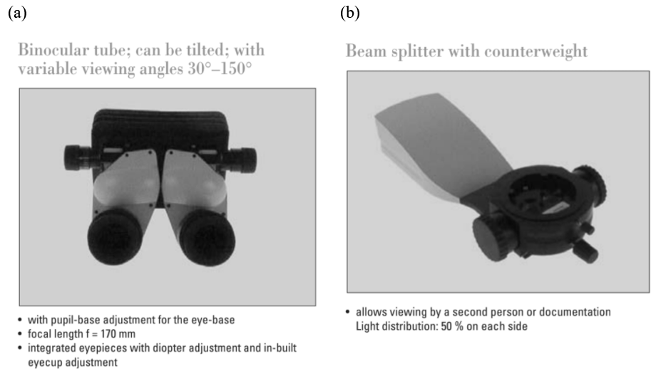
Our system is an add-on device to our customer’s surgical microscope, and our system’s design and specifications are highly dependent on the microscope. The surgical microscope that our customers use is Leica M520 MS2, as shown in Fig.1(a). Fig.1(b). This microscope consists of three main parts: binocular tube and eyepieces, a zoom system, and the main objective. Afocal interfaces are provided in between the three main parts, in which optical imaging paths are collimated to provide a modular structure of the surgical microscope. Furthermore, a beam splitter (as shown in Fig.2(b)) is provided between the binocular tube (as shown in Fig.2(a)) and the zoom system, to provide an optical path for co-observation.
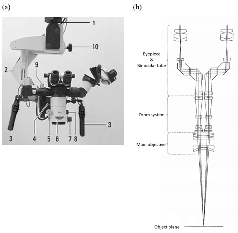
According to the Leica M520 MS2 user manual [2], the binocular tube has a focal length of 170 mm, and the intermediate image has a field diameter of 22 mm. Table 1 summarizes the main specifications of the binocular tube.
| Effective focal length | 170 mm |
| Intermediate image diameter | 22 mm |
| Full-field of view | 7.4 deg |
| Weight | 0.80 kg |
Overview of the Design
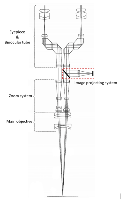
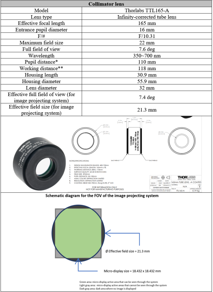
Since the beam between the binocular tube and the zoom system is collimated, we can insert the projecting system at the binocular tube-zoom system interface (as shown in Fig.3). The air gap between the binocular tube and the zoom system will be extended, and our image projecting system will be mounted in between. This will increase the amount of vignetting in the microscope but will not affect optical aberrations. The amount of vignetting can be minimized by controlling the physical dimension of the image projecting system. For our image projecting system design, we will use a collimator to collimate the beam from the USAF optical target, and the collimated beam will be focused by the binocular tube on the intermediate image plane. Therefore, the projected image will coincide with the microscope’s intermediate image. The projecting system will be attached after the beam splitter, and it will have the same mounting mechanics as the beam splitter in Leica M520 MS2. We confirmed our idea with Leica’s technical support.
To minimize the cost of the image projecting system, any optics components in our system will be off-the-shelf products. We designed the housing of the system, and all the optics components will be mounted in it. The housing will be 3D printed using polymers for the prototype product, but metal housing is desired for long-term usage.
Design and Specifications
Optical Design
Components and Specifications
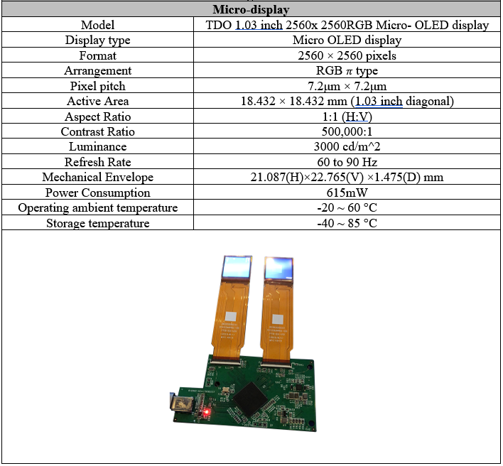
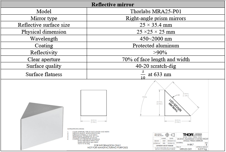
There are three main optical components in the design: the micro-display, the collimator lens, and the reflective mirror. By evaluating the performance and cost of various design forms, we determined the final design form. The following tables list the components we chose and their specifications.
** Measured from the housing edge to the image plane.
Photon Budget
The current illumination system is not attached to the microscopes or endoscope, it is a system on its own. The quality of the lenses and the angle of viewing will determine the throughput of the system.
The illumination should be specified in Lumens since it is a direct measurement of light output and can tell you the degree of brightness, which is what the surgeons need: Illumination adjustable according to their preference.
The maximum luminance that can be achieved through the projecting system:
For micro-display:
Luminance=3000cd/m^2
Area of the image of endoscope= 113.4225π 〖mm〗^2
NA= 0.0485
Etendue=Area∙π∙〖NA〗^2=2.6319 〖mm〗^2 sr
For intermediate Image:
Area=121π 〖mm〗^2
NA = 0.13265 (estimated)
Etendue=Area∙π∙〖NA〗^2=21.0126 〖mm〗^2 sr
The micro-display is the limiting factor for etendue, so the maximum luminance achievable will be the same as that of the micro-display, 3000 cd/m^2.
Since our image projecting system is mounted between the original microscope beam splitter and the binocular tube, we will add airspace between the beam splitter and the binocular tube. The added airspace will cause vignetting, and we will lose some light under the microscope view. According to the product picture of the microscope beam splitter and the binocular tube, we estimate the entrance pupil diameter (EPD) of the binocular tube as 22.55mm. In our design, the collar has a height of 40mm, and the added airspace will be the same amount. The amount of vignetting under microscope view can be calculated as
vignetting=(Clipped chief ray bundle height )/(Chief ray bundle height before adding airspace)=(40mm∙tan3.7°)/(22.55mm÷2)=22.94%
Housing Design
We designed sliding mechanics for the system’s housing. As shown in Fig.4, the collimator lens and the reflective mirror inside the housing are folded under microscope view. When switching to endoscope view, the user uses the slider to unfold the projecting system.
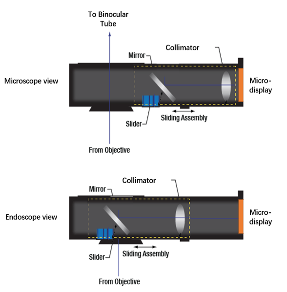
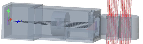
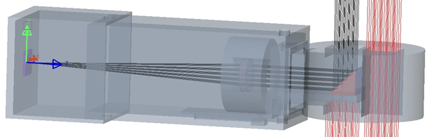
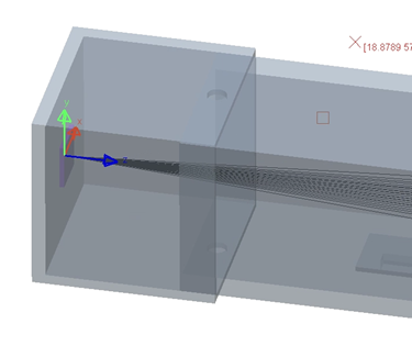
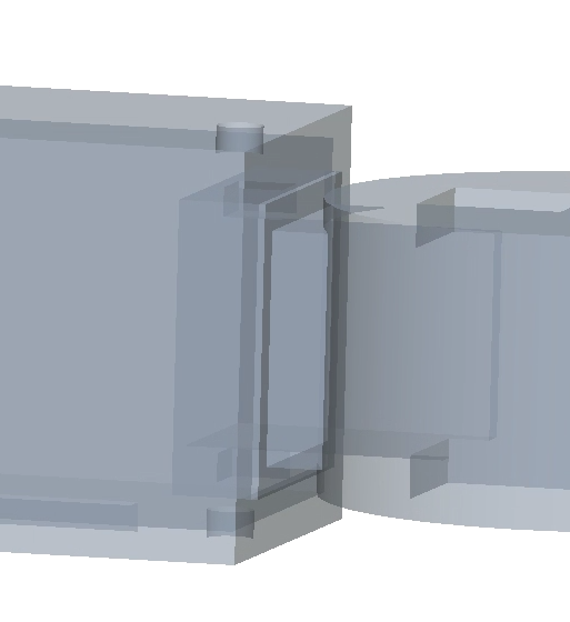
Fig 5 (a) – (d) shows the LightTools simulation of the design.
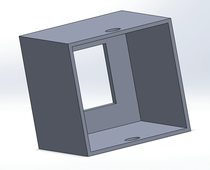
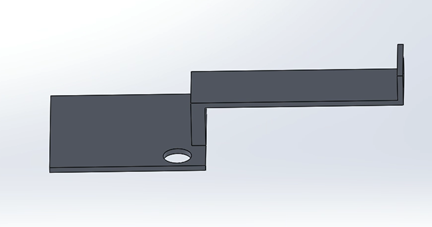
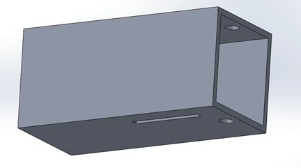
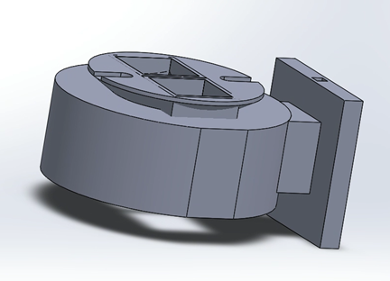
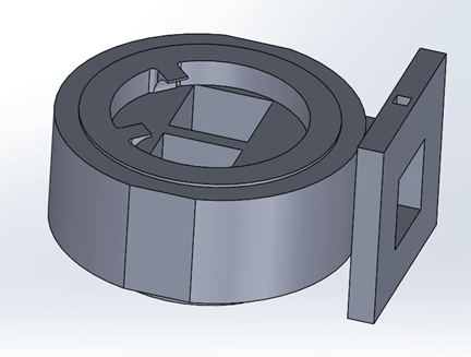
We built CAD models of the housing components for 3D printing. There are four parts: microdisplay housing, lever for sliding, housing for lever and lens, and collar. The microdisplay will be placed in the microdisplay housing (Fig. 6(a)). The reflective mirror will be mounted on the right side of the lever, and the collimator lens will be mounted on the left side of the lever (Fig. 6(b)). The lever can slide inside the housing when switching between views (Fig. 6(c)). The collar (Fig. 6(d)-(e)) will connect the beam splitter and the binocular tube of the microscope. The microdisplay housing, housing for lever and lens, and collar will be connected using tightening screws. The position of the microdisplay housing can be adjusted for focus.
Prototype
We constructed a prototype for testing using 3D printed parts. Due to the pandemic, the production and shipping time for the microdisplay was too long for the time frame of this project. Instead, we used a USAF resolution target to replace the microdisplay and evaluate the resolution of the system. This compromise had virtually no influence on the optical performance of our system.
We tested the compatibility of our system with our customers’ microscope and the optical performance of the image projecting system. We attached our system to the binocular tube (Fig 7(a)) to test the alignment and performance of the system. Fig 7(b) shows the process of testing. Fig 7(c) shows the image of the USAF resolution target taken through the eyepiece on the binocular tube, representing the view under normal operation.

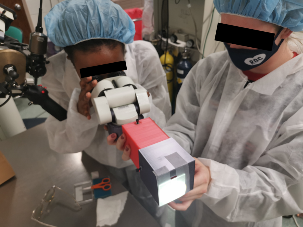

Our prototype showed a good resolution that exceeded our expectations. Fig 7(c) was taken using a phone, and the resolution of the system was beyond the phone’s resolution. We can see that the system has good contrast, resolution, and uniform illumination. From these results, our prototype shows great potential for future use in the system.
Due to the low accuracy of 3D printing, we had difficulty mounting our system to the microscope’s beam splitter. Because we were unable to securely mount the system, we had to hold it by hand which caused issues with alignment leading to an off-center and tilted image. However, the optical performance still exceeded expectations, so we still consider the whole prototype as passing initial testing. We will make fine adjustments to the 3D model for the next steps, and we recommend that it is machined from metal to be more sturdy for mounting.
Estimate of Cost
The following is the cost estimate of the prototype. For the final product, the price of the microdisplay (~$230) should also be considered. Also, the price of the system housing may vary due to different materials and fabrication methods. More prisms/mirrors may be needed to fold the beam path to make the system more compact. For comparison, a similar product from Leica has a retail price of around $44,000.
| Component | Estimated Cost |
|---|---|
| Collimator lens | $753.24 |
| Reflective Mirror | $83.06 |
| System Housing | ~$100 |
| Total | ~$936.3 |
Acknowledgments
We want to express our very great appreciation to Dr. Paul Dutcher and Dr. James Manning, our customers, for their financial support and professional guidance during the development of this senior design project.
We are also grateful for the beneficial technical advice provided by Professor Greg Schmidt, our faculty advisor.