PINGER DETECTOR
Abstract
We are developing a simple and cheap device that can be deployed in the thousands in the case of an airplane crash into an ocean or large aquatic body. This device is designed in order to reduce the time required to locate the sunken crashed vessel by emergency search teams, potentially saving more lives at a fraction of the cost of the current rescue solutions in the market.
Team
- Jason L Cobham
- Peter J Francis
- Juan Gomez Lagandara
- Muhammad Raffay Nawaz
- Minh Khoi Nguyen Do
Thank You
Our project couldn’t be possible without the guidance, feedback and assistance of Professor Jack Mottley and Professor Daniel Phinney!
Project Overview
The idea behind the creation of the Pinger Detector (underwater ultrasound signal detector) arose from the need to quickly narrow down possible locations of shipwrecks or plane crashes at sea. Currently, when such incidents occur, rescue services start circling in and around possible locations of the crash using towed sonar to find the vessel. The constant circling around of rescue boats and planes incurs huge costs in the form of fuel, maintenance of the search vessels and manpower. Furthermore, this is a time consuming process since the number of rescue vessels available is not infinite and can only cover small areas.
The project tries to explore alternatives to this. We are proposing a device that is cheap, simple and scalable to manufacture in large amounts. Thousands of such devices, each the size of a canned food container, will be dropped in and around the suspected area of the crash. These devices are basically transceivers. The devices will sink and look for the SoS signal from the sunk vessel. As soon as the required signal is detected, the device will automatically trigger a latch and make a transmitter float to the surface. This transmitter would transmit to the rescue services about the geographical coordinates of the region where the signal was detected. This will help narrow down the area of the crash site significantly.
For the scope of the capstone project, the prototype will not have the latching mechanism. The device would signal successful detection of the required signal by lighting up an LED. The prototype will be encased in a waterproof container and is tested in a one gallon container of water.
Circuit Design
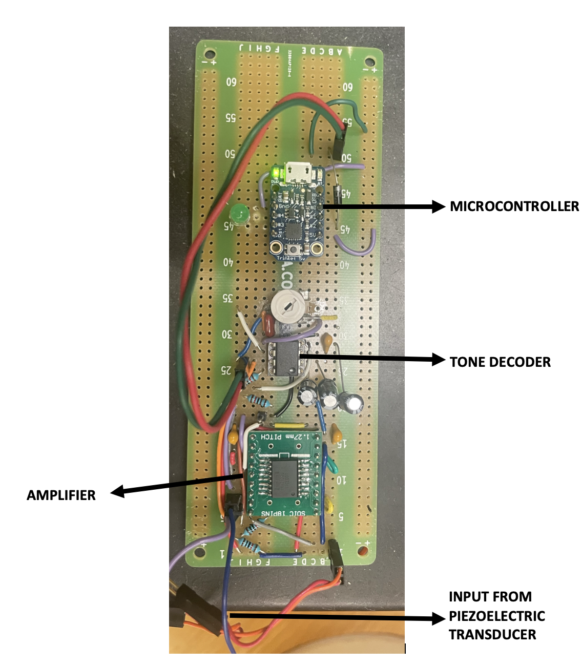
The prototype will consist of a three part design. The first part is the audiosonic wave detector (piezoelectric transducer). The output of this is connected to an amplifier. The amplifier of choice is the INA2128. The output of the amplifier is fed to a Tone Decoder, LM567x. The decoder outputs a high signal until it is fed with a signal with a preset frequency and wavelength. When such a signal is received, the decoder outputs a low signal. This output is fed to a Microcontroller (Adafruit Trinket) which toggles an LED to signal successful reception of desired SoS signal.
The design will also cover two different implementations of the circuit to understand how different signal amplifiers impact the prototype and to allow for cost comparisons. The second amplifier used is the LM368 Moreover, it will allow for better understanding of how different implementations affect the signal performance and processing.
The circuit design is shown below. The circuit for the amplifier, INA2128, is shown in Figure 1. The circuit for the Tone Decoder is shown in Figure 2. The alternate amplifier, LM368, circuit is shown in Figure 3.
Our final circuit implementation is shown below. This is encased in a water proof container.
Microcontroller
When it came to picking the microcontroller there were a few things that we were looking for. The first aspect was speed. The signal that we are trying to read has a frequency of x Khz which means that we need the clock of the processor to be significantly higher than that so it can read multiple peaks and pieces of data in the signal before the next peak. Moreover, it had to be a microprocessor which would be able to be set up in a familiar programming environment and also that it would not be too complicated to code in. There were no specific requirements or things we were looking for regarding communication or access to external analog I/O. The signal we are receiving from the tone detector is a digital signal and the one the microcontroller will be sending to the probe that will float is also a digital signal to detach. In our case, as mentioned before, the top part will not be designed so there is no need to cover for that in this microcontroller.
After looking at different microcontroller options, the chosen microcontroller was the Adafruit Trinket of 5V. This microcontroller unit uses an ATtiny85 as a microcontroller, 8k of flash memory and 5 I/O including analog and PWM ‘analog’ pins. The good thing about this board is that the 5V logic version allows it to run both at 8Mhz and 16Mhz. Since the clock is faster than the signal, we can run multiple instructions per signal period to identify the signal we obtain faster and more precisely. Moreover, the board has I2C/SPI breakout sensory interfacing, is very small and also allows it to be programmed both in C and using the Arduino IDE.
In order to recognize the periodic pulsed logic signal coming out of the tone decoder module, we perform discrete time signal processing using a microcontroller. Due to power, area, and cost tradeoffs, we chose to use an Adafruit Trinket ATtiny85 board compatible with the Arduino IDE. Knowing the decoder signal to be a periodic 1Hz, 99% duty signal square wave, the detection of a pinger signal was appropriately done using interrupt service routines (ISRs) available on the ATtiny85 board. The interrupts would trigger when the square wave transitions from high to low executing an ISR to count the number of transitions and the time elapsed between any set number of transitions which are useful for calculating the period of the logic signal. The final stage was to, after a predetermined number of transitions, determine if the determined period matches that of the of decoder and pinger signal after which a reset is was triggered and the process repeats. Additionally an LED is flickered following a successful detection of the pinger signal at regular intervals. This would be the sign for our module to trigger the latching mechanism and ascend to the surface.
Casing
The casing for the prototype is a 3D printed bottom phase carried out in ABS plastic in an FDM printer. In the case of the built prototype, since the design is printed in FDM, we had to fill in the casing with epoxy to waterproof it. In the actual design of the system, we performed tests in Fusion 360 for both impact and pressure and determined that ideally it would be better to use aluminum series 6000 and cover up the inside in tactical foam to support the pressure. The part of the casing that is designed in this prototype is the bottom part of the Pinger Detector and therefore it has all the electronics for signal detection as well as signal identification.