Team Members
- Jennifer Beahan
- Samuel Charpentier
Supervisors
- Greg Gdowski, PhD, Biomedical Engineering, UR.
- Amy Lerner, PhD, Biomedical Engineering, UR.
- Martin Gira, Senior Research Engineer, URMC.
Customers
This project has been developed with the help of surgeons and staff, at Strong Memorial Hospital and Highland Hospital.
Description
Tibial shaft fractures are a common injury and may require surgical intervention. During our team’s observation of trauma surgeries at Strong Memorial Hospital, we found the procedure was inefficient. Tools used to align bone may move, and people holding alignment are prone to fatigue. Each time a tool moves, alignment is checked or redone using X-ray. Our device clamps to the surgical bed and locks the position of instruments reducing staff needed to hold alignment and increasing efficiency.
A Fracture Fixation Device Design Process
Our team found that our story really shows how generating customer requirements can change throughout the design process. This webpage will show how our design changed due to customer requirements over the last 10 months.
First Round
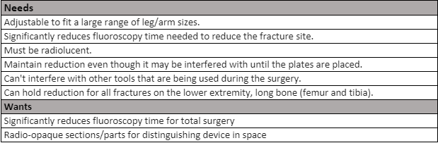
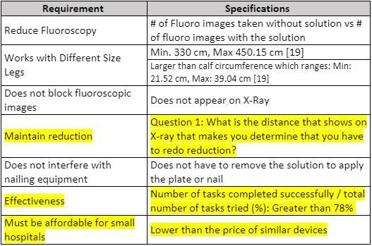
Over the summer we identified over 100 potential problems in the hospital to address. We decided to solve a problem involving how surgeons place hardware on a patient to fix their bone. Initially, by just observing surgeries, we thought their major pain point was aligning screws into the plate during minimally invasive procedures. However, after talking with surgeons we found the step that takes the most time is making sure all the fracture fragments are properly aligned throughout the procedure. This led to our first attempt at generating customer requirements (Table 1).
Second Round
We realized two things. First, we had no way to test if a product meets these needs or wants without specifications. We needed to figure out metrics. Second, we had little corroboration from surgeons that these were the items important to them. We used our first shot at customer requirements as hypotheses to test during the voice of customer interviews, so we could better understand the problem. After researching the problem further, we developed a second shot at requirements and specifications (Table 2).
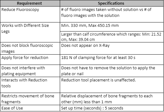
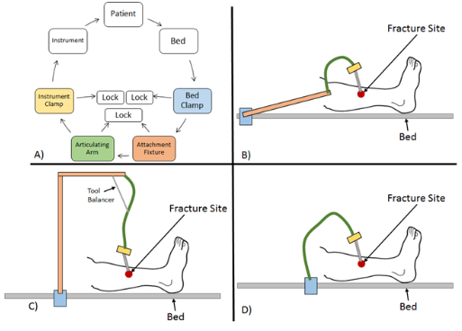
The specifications and requirements shown in Table 2, helped guide the prototypes shown in Figure 1. We designed very simple methods of realigning the bone fragment, performed killer experiments, and spoke with key opinion leaders for validation. We found that holding instruments (such as bone clamps and bone spikes) are the preferred way to realign fracture fragments. An important thing to note is that we were developing a set of specifications and even if we could not test them at the present moment, we used engineering analysis and customer interviews to determine if specifications were realistic and if they were met by prototypes.
Third Round
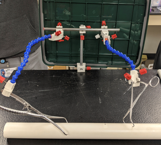
We proceeded to show the prototypes that we developed to everyone, including professors and surgeons to get some input and we found some interesting aspects that we did not consider. There is actually a preferred way to realign fracture fragments with current orthopedic trauma instruments. This altered our requirements and specifications since we had to adjust it to fit these parameters. We proceeded to develop a prototype shown in Figure 3. We knew we needed to use arms that had many degrees of freedom but were also strong enough to hold the weight of the tools, to prevent slipping. The device was also intended to be bed mounted to keep it sturdy.
After learning that holding instrumentation is the preferred way to realign fracture fragments, our requirements and specifications needed to be changed to take this into account (Table 3). At this point we felt our understanding of the problem was lacking. We tried to pin down what our device could have control over. There were also other requirements that came up from our market landscape search and hazard analysis. The major changes are highlighted. We considered multiple designs (Figure 2). Then we built prototypes using this new information (Figure 3). We knew we needed to use arms that had many degrees of freedom but were also strong enough to hold the weight of the tools, to prevent slipping. The device was also intended to be bed mounted to keep it sturdy.
Fourth Round
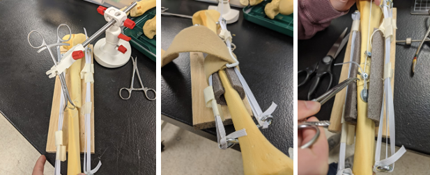
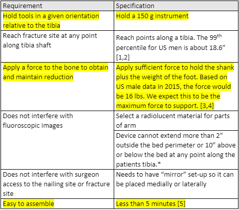
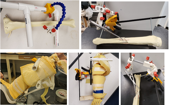
Again, we went back to our key opinion leaders in orthopedic trauma surgery space and developed the new requirements and specification shown in Table 4. This time we learned about a key feature within the surgical procedure of intramedullary nailing, which is the most common way to fixate one of these fractures. This being that the surgeon would need to be able to manipulate the limb during the surgery, therefore requiring that our tool would need to be able to move with the limb. This prompted us to build these prototypes that attached to various tools that are attached to the limb optionally by surgeons, one being a distractor, a boot used for surgery and the last being an F-Tool (Figure 4). Some of these designs incorporated a mix-and-match aspect between what tools could be attached to the leg.
This is something that had come up before in discussions, but our review of literature down-played. For us, we learned that even though you will get a variety of (sometimes conflicting) opinions from in-person interviews, it is the most valuable tool to understanding the problem. Design decisions and specifications should reflect these items. Documentation is vital to explaining how and why some items are included in requirements and others are not.
Present Round
Just like we had many times before, we went to surgeons and discussed these changes to our design. Learning, again, that we were missing a crucial detail, we now did not need to have a device that moved with the limb because one of the more common surgical procedures does not require movement. We also needed to dive deeper into the tools that it would be attaching to, one of these being a bone spike which applies a force to the limb. All of these changes led us done a new path to the move recent prototype shown below.
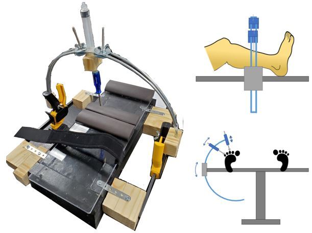
We were in the process of developing another set of requirements and specifications when work on our project was halted due to the coronavirus pandemic. Figure 5, shows our current prototype. Surgeons further explained to us that at certain steps in the procedure the leg moves minimally. For that reason, we returned to some bed mounted ideas. The current prototype tries to make use of added stability from using two support points instead of a cantilever.
What we want people to learn from our process is to ask as many questions as possible about the problem. Dive deep into the requirements and try and be a master of the procedure. These are crucial steps in truly developing the best possible device.