Team

Dominique Houslin 
Elyse Jones 
Rebeca Zapaich 
Humfrey Kimanya
Mentors
Sponsor
Dr. Calvin Uzelmeier
Project Manager
Professor Christopher Muir
Abstract
Sponsored by the Rochester Museum and Science Center (RMSC), the team was tasked with creating an interactive display that would educate users about a specific scientific topic. The display chosen should educate the public about fluid dynamics concepts including lift and drag forces and laminar and turbulence flows. A wing with two flaps was manufactured and mounted to a translation stage. A flap actuation system was added to allow the user to change the pitch of the flaps and observe the difference. A fan bank provided by the museum allowed for the assembly to be placed in a display case that acted similarly to a wind tunnel. The display was tested at the museum with museum guests, and subsequent revisions were made to improve the usability and lifetime of the design.
Problem Statement
The problem that the Rochester Museum and Science Center (RMSC) aims to solve is to expand the scientific horizons of children. As a result, RMSC has a plethora of exhibits to help their target audience, families with children ages 5-15, understand complex science phenomena, for example: optics, motor vehicle, and circuit breakers. Their exhibits aim to captivate and enlighten children and their families through incorporating interactive components to each exhibit. The set-up or layout of the museum is conducive to the education of children, and this encourages them to explore and ask questions.
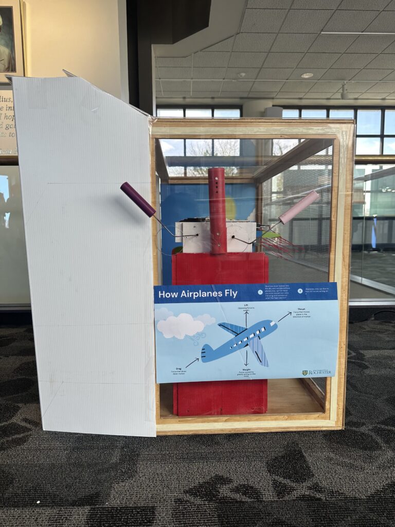
The goal of the airline wing exhibit, which will go in the How things Work Exhibition, is to allow children to have an up-to-close experience with the fluid dynamics of flying aircrafts. This exhibit serves to engage users as they vary the wind speed of the fan bank and adjust flaps to observe aerodynamic and fluid dynamic concepts, including lift, drag, laminar flow, and turbulent flow. Exposure to these concepts early will help children who encounter such terminology easily visualize and understand what is occurring.
Requirements
- Designed for families with children, targeted towards ages 5-15.
- Has an interactive component to the exhibit.
- Must be universally accessible– local to the NY area (Rochester).
- Should be intuitive and easy for children and their families to understand and use.
- Should be safe for the audience (i.e.: approved by the RMSC staff).
- Labels should not be overwhelming (i.e.: very wordy).
- Design must be iterative.
Specifications
- The target age range of users is between 5 and 15 years old.
- The target height of the interactive portion of the must be between 24 in and 32 in.
- The label must not have more than 100 words.
- The exhibit must fit withing a 5×5 foot floor space.
- The factor of safety must be at least 2.
- The maximum grip strength of the handle must withstand a grip strength of 58.3 N (13.1 lbf) [1].
- The maximum pushing force required to operate the handle must be no greater than 5 lbf.
Design Selection
The team brainstormed exhibit ideas that consisted of ‘day to day’ items that the general public comes in contact with. Each idea is associated with a science concept and is presented in a manner that is engaging, interactive, and accessible to all groups. A pugh matrix was used to determine what science concept to protype for the museum, with the ROV submarine being the baseline.
Table 1: Pugh Matric used to decide what scientific concept to use for the exhibit at RMSC
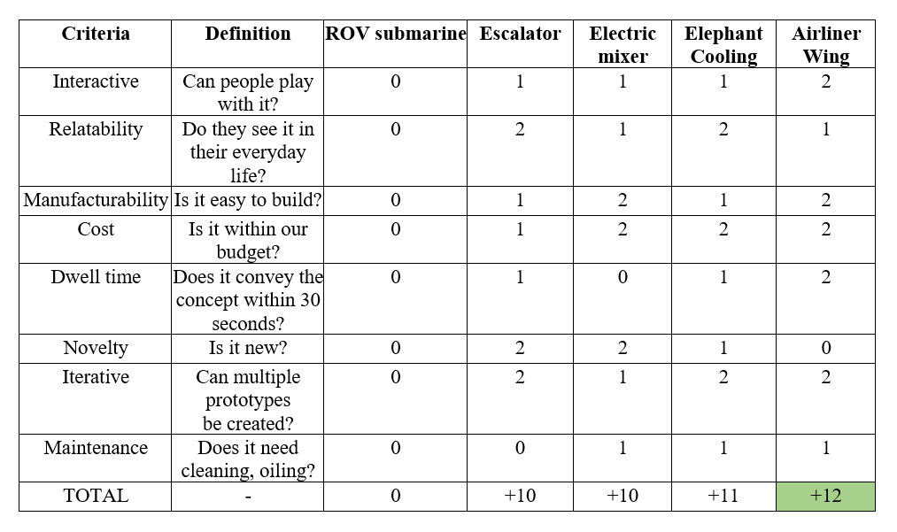
The airline wing, which explores fluid dynamics, was the science exhibit the team decided to go forward with.
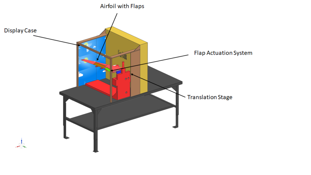
Design Components
The exhibit can be divided into four subsystems: translation stage, the flap actuation, airfoil, and stand (case).
Manufacturing
Below is the manufacturing process for each subsystem in the airline wing exhibit.
Translation Stage
The translation stage consisted of a stand with a board, which the wing was attached to support its weight. The stand has a bracket which keeps the board in the stand. On various faces of the support stand, press fit roller balls were inserted by using a hole saw with diameters that matched the roller balls. The position of the first three roller balls was determined by identifying planes where the translation board was sandwiched. The fourth roller ball was situated against the base of the board to restrict the board from causing friction against the support stand.
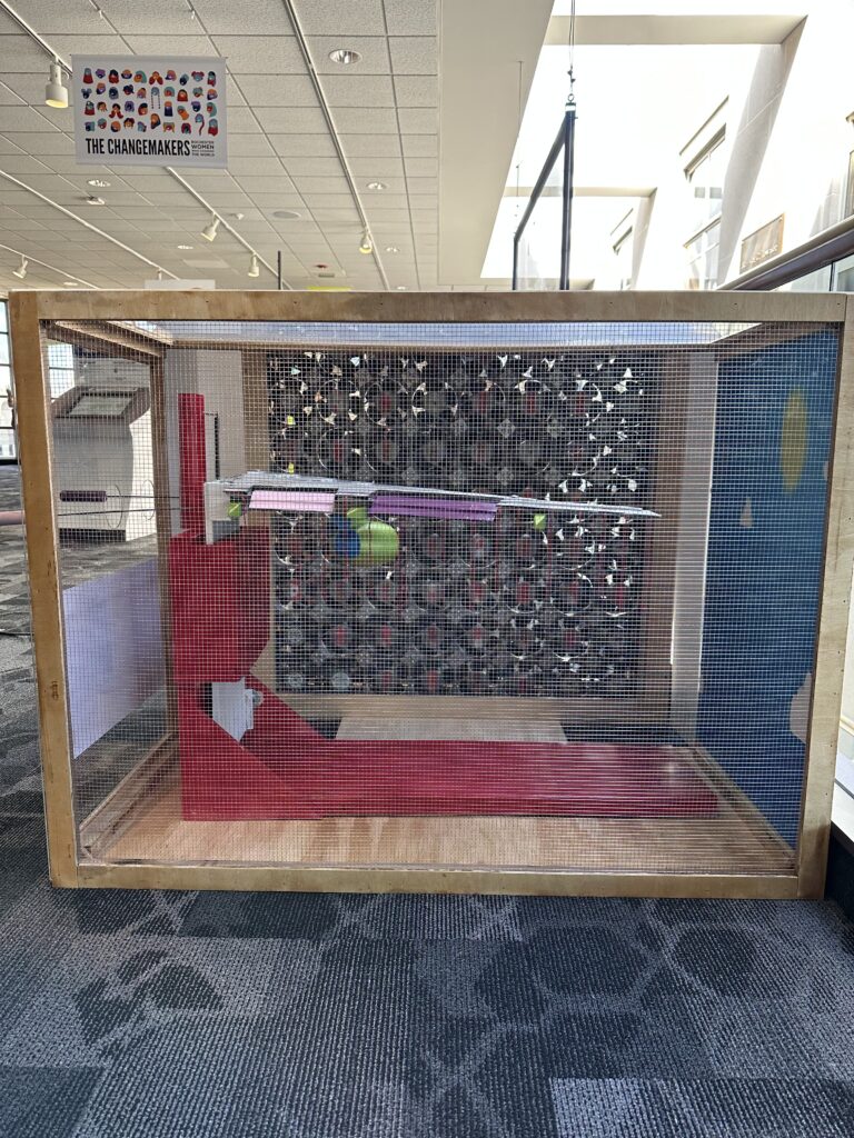
Display Case
The display to house the airplane wing and the translation stage was built by Mr. Bill Mildenberger. The frame of the box and one wall of the box was constructed from plywood. The top of the box and the left-side of the box when looking towards the fan bank were constructed from acrylic sheets of 1/16 in thickness. Acrylic was used because of its ability to cut holes as an opening to attach the handles to the flap actuators on the laser cutter without the risk of exposure to hazardous fumes. In addition to the safety properties of the material, the cost of the material was considered. For the top and side, 42×36 in and 24×36 in acrylic sheets were respectively attached to the plywood frame using double-stick tape. The back-wall of the box was covered with ¼ in x ¼ in steel wire mesh. This material was chosen to prevent users from directly touching the wing assembly.
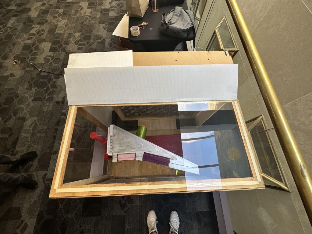
Airfoil
The wing included the airfoil, the engine, flaps, and tail fins. The team began by 3D printing the engine and ailerons since they were purely for aesthetic purposes. The functional components of the wing include the airfoil and the flaps. Initially, the airfoil section of the wing was to be manufactured on a CNC machine by first cutting the perimeter using a 0.5 in end mill tool followed by contouring the streamline faces using a 0.5 in ball mill tool. This procedure was unsuccessful because of the warped nature of the stock wood making it difficult to rest on the base plate. The team then switched to using the laser cutter, making splines of 0.1 in thickness. After laser cutting, the layers were then glued together. The flaps were attached to the airfoil using live hinges made of duct tape. To complete the wing’s manufacturing, the 3D printed engine, ailerons, and yarn (to visualize air flow) were glued to the airfoil.
Flap Actuation
The manufacturing of the flap actuation was done by the team. Using pliers, the rods were bent to secure it to the plate of the coupling. On the same plate, two holes were drilled on either side of where the rod hooked into, and a tie was fed through the holes to securely fasten the rods. The plate of the coupling was fastened into a piece of metal bent at a right angle. A small bushing was pressed onto the plate and allowed for motion. Another hole in the plate was drilled for the smaller wire of the flap to fit into, and the end of this wire was also bent with pliers to avoid it from slipping out of the coupling. A small fixture made from sheet metal was attached to the flap, fixing the smaller wire to the flap.
Prototyping
The first iteration of the exhibit was taken to RMS for on-site testing. One hundred and five (105) people interacted with the exhibit. Using a checklist, observations and design modification notes were made.
Tester Demographic
Parents – 38
Children- 60 (26 girls & 34 boys)
Elderly- 7
Repeat users- 8
Design Observations
Flap actuation usuage is not intuitive to users.
Children were able to recognize the design and understand why it was in the museum.
The airline wing was heavy as it was unable to demonstrate lift and drag.
Design Changes Needed
Include cue questions on the label to show that the audience observes and understands the science concept being communicated.
Modify the handle usage based on observed user intuition.
Secure the base of the translation stage to the case.
Social and Environmental Implications
Relatability Concerns
An area of concern among the team was the relatability of the exhibit, as not everyone has experienced flying on a plane. The team and sponsor were concerned because Rochester is an inner-city area, with more low-income families implying that there is a low probability that the audience having flown in an airplane before. The average household income is $52,116, with a poverty rate of approximately 36%. However, all participants were able to recognize the airline wing and those who had not been on one expressed excitement for when the time came to go on one.
Material Selection
The environmental impacts of the exhibit are minimal as the components can be reused for other exhibits within the museum. The final wing was made with Expanded Polystyrene (EPS) foam . Since the wing was laser cut with a device that has an air suction system, no toxic fumes would be emitted. According to the safety data sheet (SDS) for EPS, from Kay-Metzeler Experience and Research, EPS is physically and chemically stable and non-toxic. It is safe for designers and exhibit users to come in contact as it has been approved for use by regulatory bodies worldwide, once proper ventilation is in place. This material is biologically inert and not a skin, eye, or respiratory irritant. The only drawback is that this material is combustible, so the exhibit needs to be in an area where smoking is prohibited and in a cool area during the summer.
Energy Intensive
The fan bank is compromised of several tiny fans , similar to the ones that cool supercomputers. This means that lots of energy is required to run the exhibit, especially since it would remain on for the entire day.
Non-renewable energy resources are used in electricity production. As a result, long term use increases the greenhouse gas emissions which contributes to global warming.
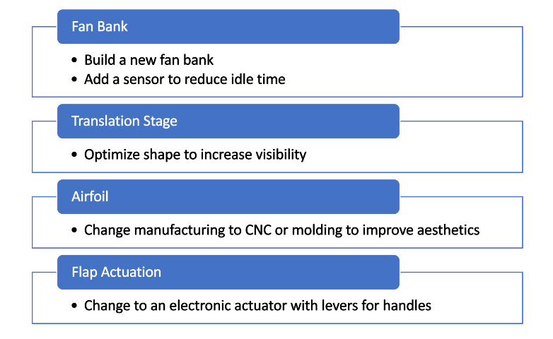
Future Works
Since this is a prototype, there are many ways that this can be improved. After looking at the social and environmental implications of the exhibit, we identified some areas for improvement: