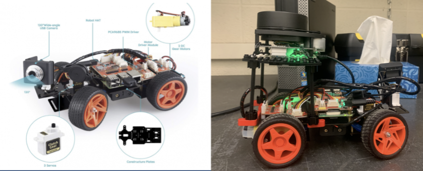
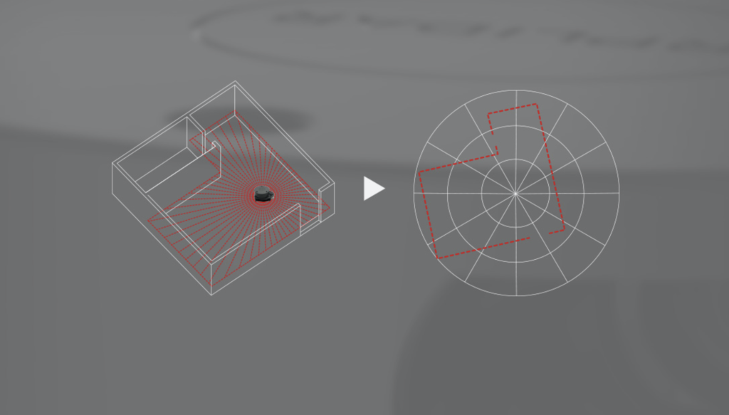
Using the interactive detection robot, the user will be able to wirelessly control the device and visually see its surroundings using the camera module. The RPLidar enables a 360° view of the robot’s environment.
Initial goal vs Accomplished goal
Our initial project expectations was to create an autonomous robot that is cable of 2D SLAM mapping a room and use that information to detect and avoid objects while optimizing the path it will be taking. Due to many difficulties with the RPLIDAR A1 and getting it to work on Robostudios, our focus for this project shifted into creating an interactive robot that allows the user to control it wirelessly and get visual feedback from the robot using the camera and lidar.
Goals Accomplished
- Finished building hardware (robot car, RPLIDAR, and RPLIDAR stand)
- Tested the software program using Python 3
- Tested robot mobility and sensors
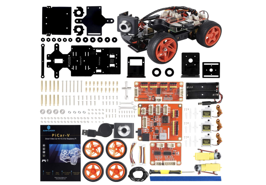
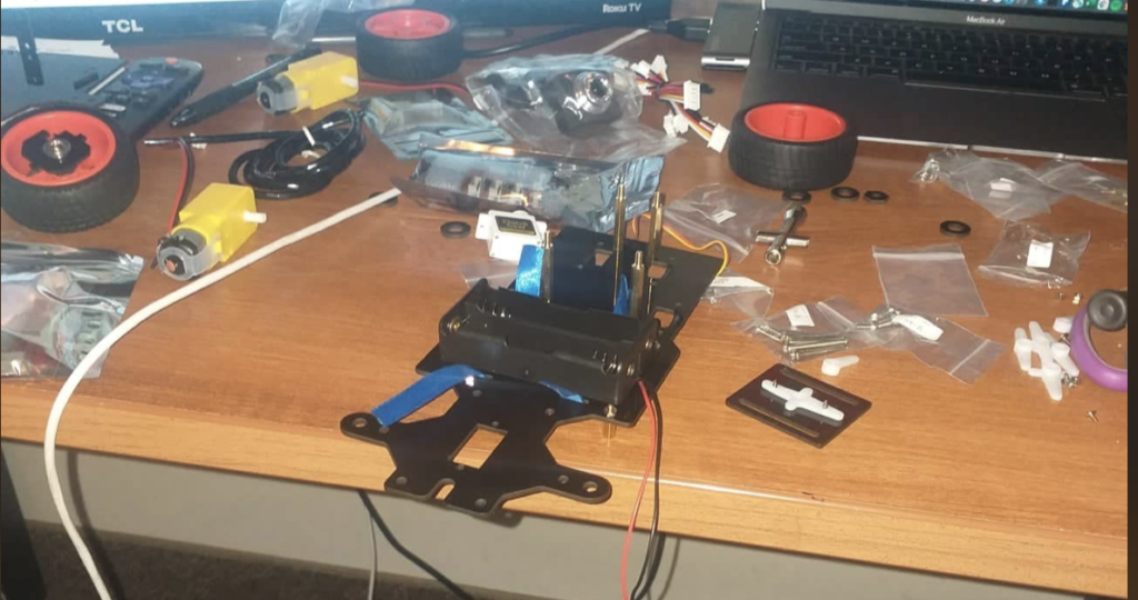
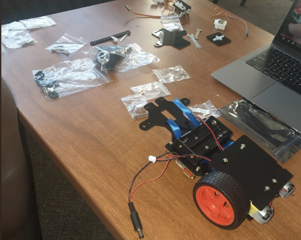
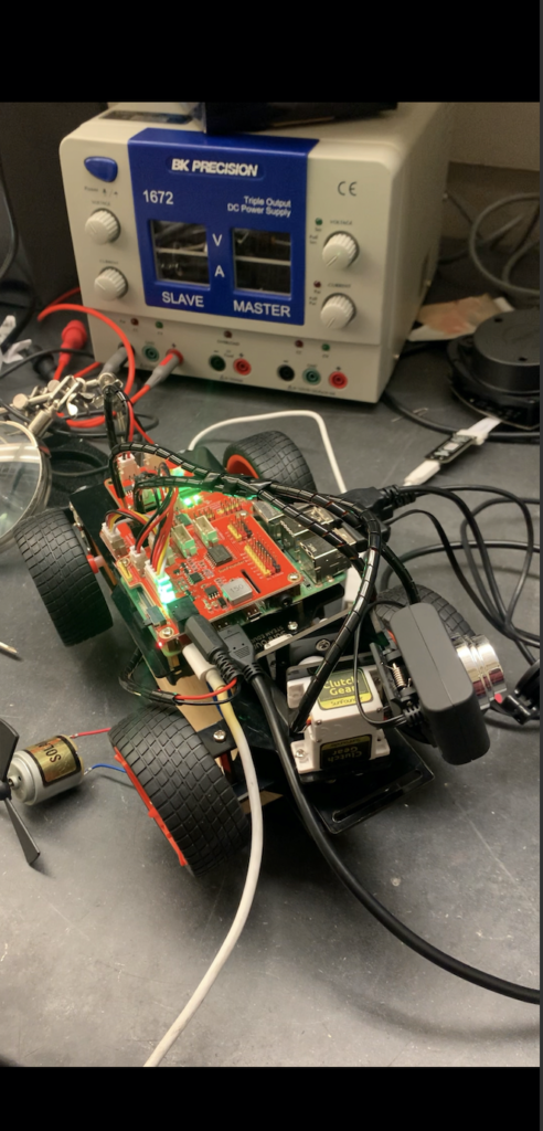
The above pictures show the building of the robot car from individual parts
Testing mobility and motors of the car
This is a visual representation of the code running to make the robot move around a room wirelessly
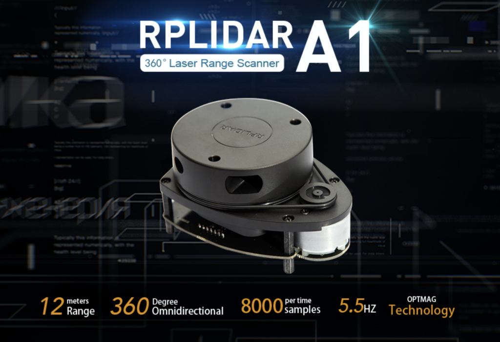
RPLIDAR A1
RPLIDAR Recap:
RPLIDAR A1 is based on laser triangulation ranging principle and uses high-speed vision acquisition and processing hardware developed by Slamtec.
The system measures distance data in more than 8000 times per second.
Goal Accomplished:
- Using Raspberry pi 4 model B for data visualization obtained from the RPLidar
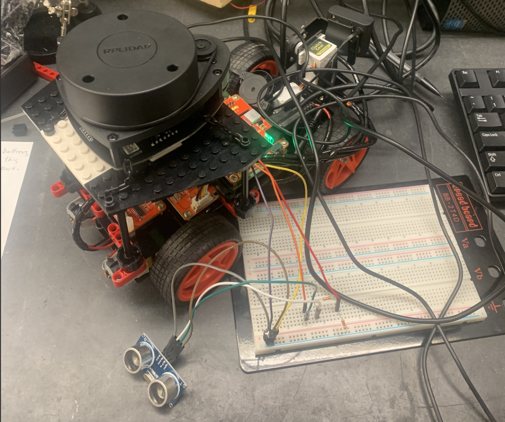
- Integrating the RPLidar on to the robot car

Attempted Approaches for Mapping
- The first approach we tried was to use RoboStudio for SLAM mapping, which did not work because RoboStudio was not able to SSH into the car.
- The second approach was to extract the distance and angle from the RPLidar program and use this information for object avoidance. The problem with this approach is that when the code from the RPLidar imported to the program to run the car, there was a function called to the RPLidar and never left the RPLidar function call to execute the rest of the program. Many attempts for a trigger call were made, but with out success.
- Connecting an ultrasonic sensor would have measured thee distance from the car to any object in the room, however this did not work because the hat on the Raspberry Pi blocked the GOP pins, which needed to be connected to the ultrasonic sensor in order to run.
Possible Alternative Approaches
- A different approach would be to get the RPLidar program to extract the angle and distance. From there, this data would be integrated to the car program and ensure that all the parts work together before software integration.
- Building the software from scratch would cut out the unnecessary complexity in the RPLIDAR program as well as the car program.
The following zip file contains the main software used in the development and execution of the interactive Detection robot