The Virtual Skylight project is an indoor lighting system, created by the senior design team, to simulate the sun’s visual rays. Design inputs were derived from our interactions with our customer Luxtech, represented by Bill Green, and our advisor, Greg Schmidt.
The Team
Customer
Bill Green – Optical Engineer at Luxtech
Faculty Advisor
Dr. Greg Schmidt
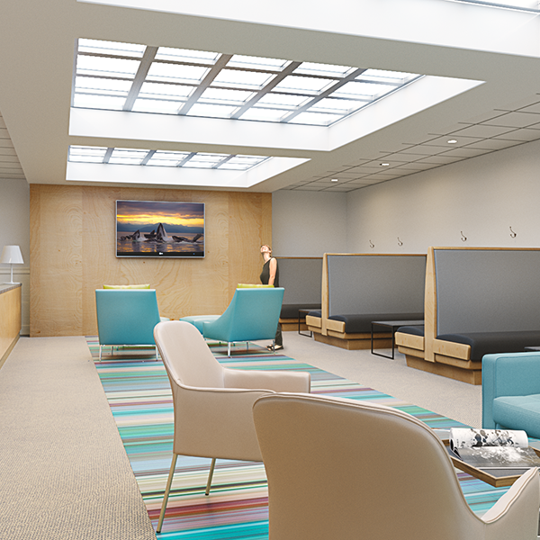
Vision: The vision of this product is to be a major lighting component anywhere natural sunlight is unavailable. It will provide enough light to give the impression of the real sun, with a similar beam angle, in order to create a visible “sun” beam. There will also be a simulated sky meant to illuminate the full room. Two different optical systems will be used to achieve these goals. We want this product to look realistic so that the benefits of natural sunlight may be achieved where it was not previously possible.
Specifications
When we started out the project, we expected the system to meet a few key specifications. Firstly, we expected a realistic impression of the sun, with a diverging sunbeam angle of less than plus or minus 2 degrees, and a synthetic image of the sun formed at near infinity. The system was expected to be less than 10cm thick and under 50 kg/m2. We also hoped the system would perform to normal lighting standards within normal indoor environments.
For the final prototype, the system ended up to meet a few key specifications, while other specifications were not able to be tested due to the time constraint. The system is 10.7 x 10.7 cm, with a thickness of less than 6 cm and under 10kg/m2. The system was able to perform to normal lighting standards within standard indoor environments.
Below is a tabular view of the specifications for the system:
| Description | Desirable | Limit | Achieved |
| Diverging Beam θsun | 1◦ | ≤4◦ | |
| Panel Size | 20 x 20 cm | 10 x 10 cm | 10.7 x 10.7 cm |
| Power | >60 W | ≈60 W | |
| Weight | <50 kg/m2 | <50 kg/m2 | <10 kg/m2 |
| Thickness | ≤4 cm | ≤10 cm | <6 cm |
| Efficacy | 60 lm/W | ||
| Sunbeam/Sky Ratio | 90-10 | 85-15 |
Preliminary Design
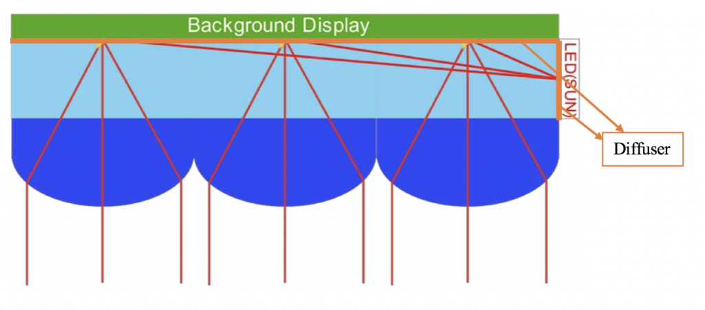
We decided to use a back-lit system for the background display to simulate the sky and an edge-lit system to simulate sunbeams. This will best simulate the Sun as an infinite object with parallel rays. We consider this design to be the most efficient, while also allowing for the desired ratio between the artificial sun and sky. The system will also utilize diffusers, gels and scattering paper to help create a light-box like system. It will improve the output of the system and also create a more uniform intensity. For the edge-lit system, it will use reflecting sites as shown above to redirect the beam to the lens array. Each system will be lit from LED’s and controlled from a dimmable power source.
Material Selection and LightTools Model
The prototype design of the optical parts of Virtual Skylight was done in LightTools. This is to enable tolerancing through the LightTools ray simulations. This will help to streamline the design process.
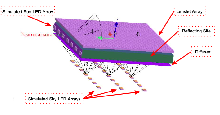
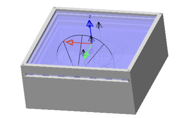
Version 12 of the LightTools model is shown below. This version shows the optical components of the Virtual Skylight. As mentioned above, there are two different optical systems for achieving simulated sun and simulated sky.
On the figure below you can see there is LED sources for both of the background display and on the sides of our system. For our LED source, we used the LUXroll Tunable White (TW), directly provided by our customer, Luxtech. These strips feature tunable white technology, allowing users to adjust color temperature of the light panel from cold to warm in real time so they can adjust the panels to mimic different times of day. This is achieved by having two separate diodes for two separate color temperatures.
For the simulated sky we used a two product method of diffusing and color correcting. For the color correction we used a lighting gel from Rosco. Since one of our members is versatile in technical theater we have a good idea of what gels provide the necessary color correction. After the color correction the simulated sky light is sent through a bat wing diffuser, in order to ensure that while there is diffusion, there is also a push of power out to the sides, allowing an even distribution of light throughout the illumination plane.
We also used an off-the-shelf lenslet array from Japanese company NTKJ because they offered the smallest focal length, allowing room for the rest of the system to fit within the packaging constraint, and to create the synthetic image of the sun.
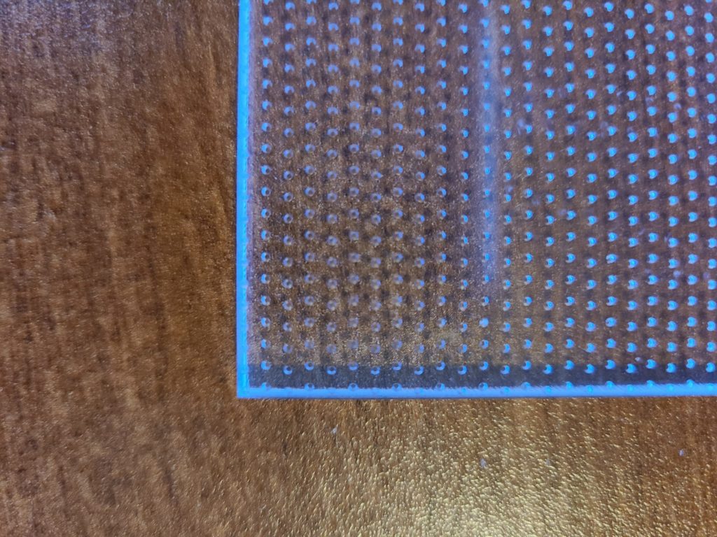
We created custom light guides/reflecting site in order to create the synthetic image of the sun. We used the machine shop at Taylor Hall to drill an array of TIR cones into sheets of acrylic in order to match pitch with our lens arrays. We have decided on using a reflection based system rather than a scattering one due to worries about directing enough light outwards. Unfortunately, we ran into some issues with this manufacturing process, as will be detailed later.
SolidWorks Model
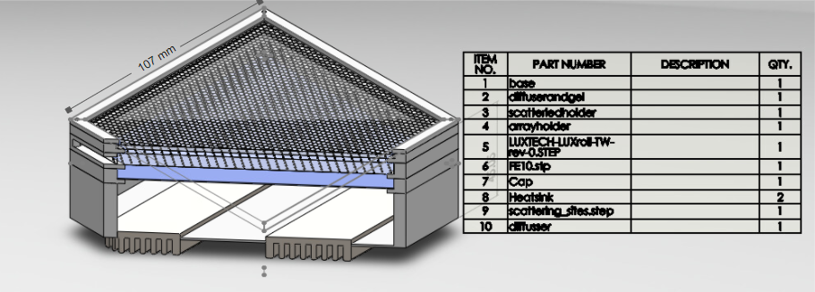
We have also constructed a SolidWorks model of the entire system to give us the ability for us to print non-optical 3D parts. This will help reduce the cost of developing the prototype and streamline the design process. Our plan was to incorporate a poker chip assembly design. A poker chip assembly design is a modulated design with segments for each layer of the optical system, with each stack making up a “pane” of the skylight. The modulated design allows for more degrees of freedom for alignment and tolerances. It also enabled for a more effective 3D print setup, ensuring that even if one part failed during print, most of the model was still intact.
Combined Model and Irradiance Profile
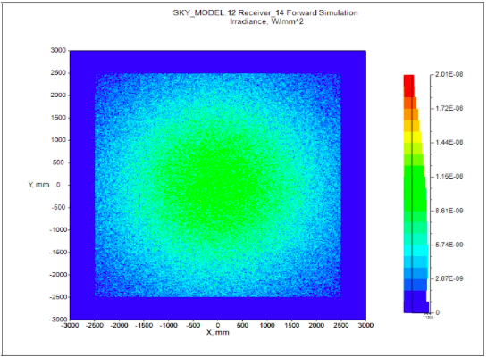
We combined the LightTools model and the SolidWorks Model to better simulate the system.
We then were able to run an irradiance simulation to see if the module was performing to our expectations, and if there were any bugs with the simulations. The figure for the simulations are displayed below. In the figure it is important to note that this was taken 1 m away from the skylight and covers a 5 m x 5 area. We can see that the illumination of the system seems to be fairly uniform.
Individual Components Testing
Before we went right into assembling our final prototype, we tested individual components to see if they perform properly.
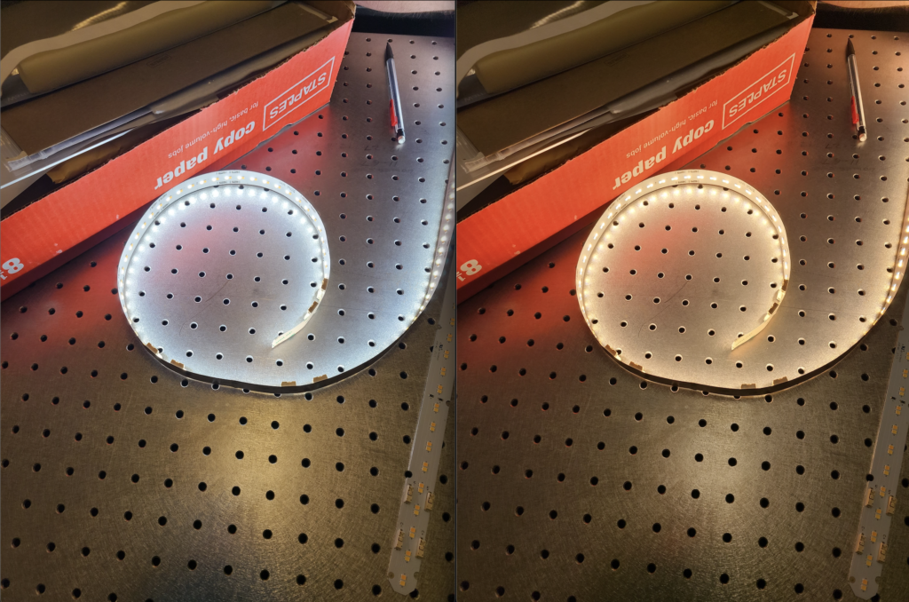
As mentioned above, we used the LuxRoll Tunable White LED strips that uses tunable white technology, allowing users to adjust color temperature of the light panel from cold to warm in real time. So the figure below shows how the LuxRoll Tunable White LED strips working with a driver that allows users to adjust color temperature.
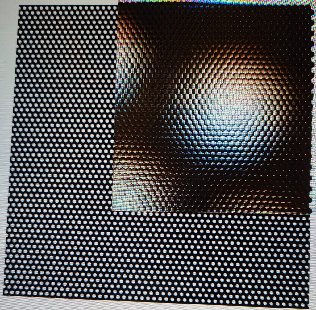
To test our lens-let array, we used a test image to see the pitch matching. Matching the pitch of the lens array allows us to create larger individual images from the array.
Unfortunately, the engraver used to drill the holes for our lightguides had issues with the alignment as it progressed in one direction of the part. This resulted in reflecting sites that are lined up very well on one side of the system that gradually fall more and more out of alignment towards the other side of the part. An attempt at a temporary fix also ended up with issues, as the new process used resulted in the wrong spacing between sites. More time would be needed in order to fix this error, and we are currently waiting on a response from Taylor Hall to move in that direction.
To test our diffuser and gel we used the simulated sky led module and rested the diffusers on top. With the LEDs active we were able to achieve a semi-uniform beam out of the system that resembles the diffuse light from the sky. The design produces enough ambient light to illuminate the room to some degree, even with only one of these modules. The Diffusers did need to be changed to find the best level of diffusion. This usually resulted from one diffuser sheet being rotated 90 degrees from the other. Below is an image of the diffusers in the module.
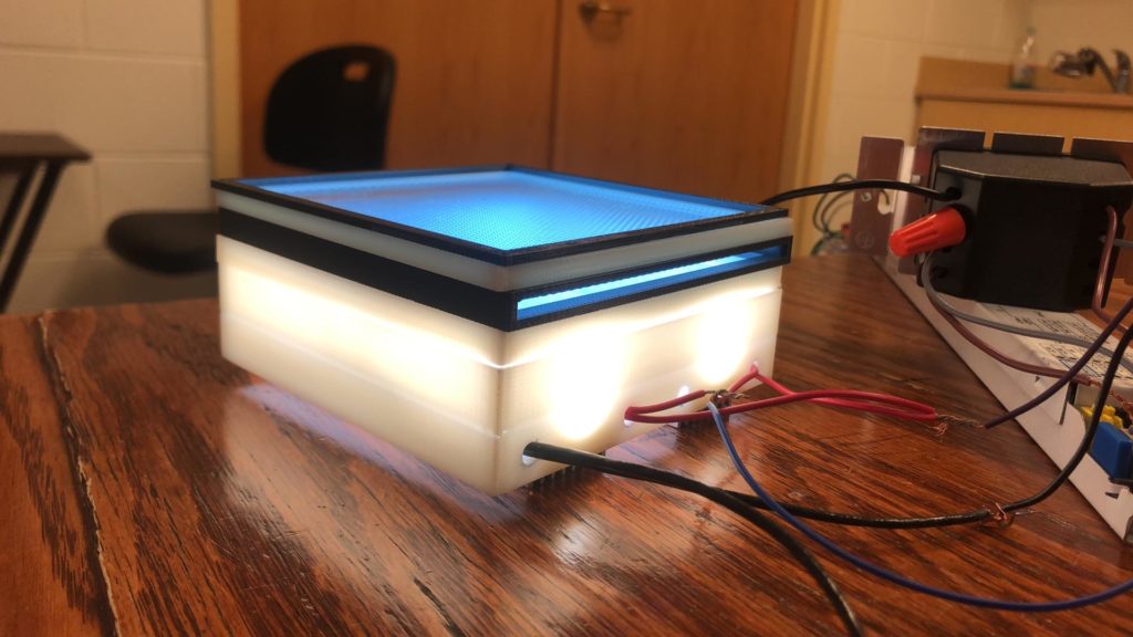
The Prototype
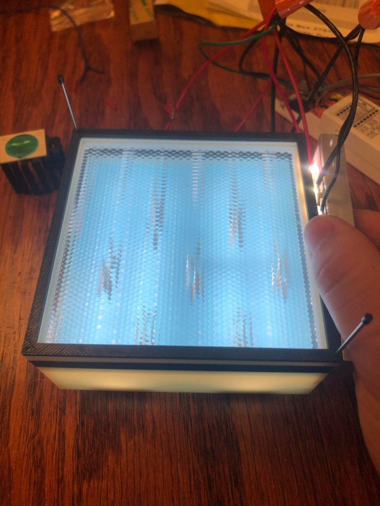
Due to difficulties in the manufacturing process and time constraints, as well as problems with machine shop equipment, we were unable to create a well-aligned lightguide to work with the system. With what we did make, we were able to create a proof-of-concept design that incorporates virtual images within the lighting device, but due to the misalignment of the lightguide, there are multiple misshapen image, rather than our goal of a single image of the “sun.” With slightly more time, we would be able to manufacture a proper part, and achieve what we originally intended to.
Challenges
Technical Challenges
We faced many technical challenges during the design process. Some of those being the creation of reflective sites, reducing printed material, and aligning the system. Creating the reflective sites was probably the hardest challenge that we have, and still are, facing. We faced significant issues in the manufacturing process, with errors in the machinery causing misalignment in the reflection sites. We also faced issues with attempts to overcome the machine error. On top of that we also need to make sure the drilled sites are the same size throughout the pane. With these two constraints, the reflection sites are still being worked on.
When printing the solidworks design for the first time we were confronted with the fact that our design would take too long and be too costly to print. This was overcome by going back into the lab and making measurements to reduce as much material as possible. In all we were able to reduce the amount of material by 4X the original design. This reduction lowered the cost of the print and reduced the time to a functional limit.
Aligning the system took the most time when creating the working prototype. Since pitch matching is one of the most sensitive factors in ensuring the system works, as well as our issues with creating a suitable lightguide, it took a great deal of time to get it to the point where we were able to get a virtual image from the simulated sun section. Some time was also given to ensuring that the diffusers were working properly. The orientation of the diffusers greatly impacts the performance of the system, and time is needed to make sure that they are correct.
Other Challenges
Accomplishing senior design projects in the time of COVID-19 was especially challenging with the social distancing and travel restrictions, and it was even more challenging for our team. First of all, one of our team members, Lisa, was stuck in China for the entire senior year due to travel restrictions. To solve this issue, we arranged team members’ responsibilities to allow Lisa to do more logistics work behind the scenes, while Luke and Brian were in the lab doing all the hands-on work.
Secondly, also because of the pandemic, it takes much longer for parts acquisition and manufacturing. We tried our best to order and manufacture parts ahead of time to ensure things were ready for assembly. However, due to the time constraint of the senior design project, we were not able to perform a full set of testing on the finished prototype.
Overall, we believe that we have overcome most of the challenges by utilizing the resources that we had access to within the time constraints.
Acknowledgment
We would like to express our very great appreciation to Bill Green, our customer, for his valuable support and professional guidance during the development of this senior design project.
We are also grateful for the beneficial technical advices given by Professor Greg Schmidt, our faculty advisor.
Special thanks to Professor Wayne Knox, the instructor of the senior design course, for his help in providing us lab space and useful advices when reviewing our documents.